Page 73 of 96

Periodic maintenance and adjustment
6-30
6
If a fuse is blown, replace it as follows.1. Turn the key to “ ” and turn off
the electrical circuit in question.
2. Remove the blown fuse, and then
install a new fuse of the specified
amperage. WARNING! Do not
use a fuse of a higher amperage
rating than recommended to
avoid causing extensive dam-
age to the electrical system and
possibly a fire.
[EWA15132]
3. Turn the key to “ ” and turn on
the electrical circuit in question to
check if the device operates.
4. If the fuse immediately blows
again, have a Yamaha dealer
check the electrical system.
EAU68470
Replacing the headlight bulbThis model is equipped with halogen
bulb headlight. If a headlight bulb
burns out, have a Yamaha dealer re-
place it and, if necessary, adjust the
headlight beam.NOTICE
ECA17871
Headlight lens:
Do not affix any type of tinted film or
stickers to the headlight lens.
Do not use a headlight bulb of a
wattage higher than specified.
1. Fuse box
1. Ignition fuse
2. Signaling system fuse
3. Backup fuse (for clock)
4. Headlight fuse
5. Radiator fan motor fuse
6. Spare fuse
16
12345
Specified fuses:
Main fuse:
30.0 A
Headlight fuse:
15.0 A
Signaling system fuse:
7.5 A
Ignition fuse:
15.0 A
Radiator fan motor fuse:
7.5 A
Backup fuse:
7.5 A
UB04E0E0.book Page 30 Wednesday, September 2, 2015 3:51 PM
Page 74 of 96
Periodic maintenance and adjustment
6-31
6
EAU44941
Auxiliary lightThis model is equipped with an LED-
type auxiliary light.
If the auxiliary light does not come on,
have a Yamaha dealer check it.
EAU24182
Tail/brake lightThis model is equipped with an LED-
type tail/brake light.
If the tail/brake light does not come on,
have a Yamaha dealer check it.
EAU62590
Replacing a turn signal light
bulb1. Remove the turn signal light lens
by removing the screw.
2. Remove the turn signal light bulb
socket (together with the bulb) by
turning it counterclockwise.
1. Auxiliary light
1 1
1. Turn signal light lens
2. Screw
1
2
UB04E0E0.book Page 31 Wednesday, September 2, 2015 3:51 PM
Page 75 of 96
Periodic maintenance and adjustment
6-32
6 3. Remove the burnt-out bulb by
pulling it out.
4. Insert a new bulb into the socket.
5. Install the socket (together with
the bulb) by turning it clockwise.
6. Install the turn signal light lens by
installing the screw. NOTICE: Do
not overtighten the screw, oth-
erwise the lens may break.
[ECA11192]EAU62670
Replacing the license plate
light bulb1. Remove the mudguard by remov-
ing the quick fasteners.
2. Remove the rear fender lower
panel by removing the bolts and
screws.3. Remove the license plate light
bulb socket (together with the
bulb) by pulling it out.
4. Remove the burnt-out bulb by
pulling it out.
1. Turn signal light bulb socket
1
1. Mudguard
2. Quick fastener
1
2
1. Bolt
2. Screw
3. Rear fender lower panel
1. License plate light bulb
2. License plate light bulb socket
3
2
1
2
2 121
UB04E0E0.book Page 32 Wednesday, September 2, 2015 3:51 PM
Page 76 of 96
 by pushing it in.
7. Install the rear fender lower panel
by installing th")
Periodic maintenance and adjustment
6-33
65. Insert a new bulb into the socket.
6. Install the socket (together with
the bulb) by pushing it in.
7. Install the rear fender lower panel
by installing the bolts and screws.
8. Install the mudguard by installing
the quick fasteners.
EAU24351
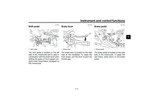
Supporting the motorcycleSince this model is not equipped with a
centerstand, follow these precautions
when removing the front and rear
wheel or performing other mainte-
nance requiring the motorcycle to
stand upright. Check that the motorcy-
cle is in a stable and level position be-
fore starting any maintenance. A
strong wooden box can be placed un-
der the engine for added stability.
To service the front wheel
1. Stabilize the rear of the motorcy-
cle by using a motorcycle stand
or, if an additional motorcycle
stand is not available, by placing a
jack under the frame in front of the
rear wheel.
2. Raise the front wheel off the
ground by using a motorcycle
stand.
To service the rear wheel
Raise the rear wheel off the ground by
using a motorcycle stand or, if a motor-
cycle stand is not available, by placinga jack either under each side of the
frame in front of the rear wheel or under
each side of the swingarm.
UB04E0E0.book Page 33 Wednesday, September 2, 2015 3:51 PM
Page 77 of 96

Periodic maintenance and adjustment
6-34
6
EAU24361
Front wheel
EAUN0670
To remove the front wheel
WARNING
EWA10822
To avoid injury, securely support the
vehicle so there is no danger of it
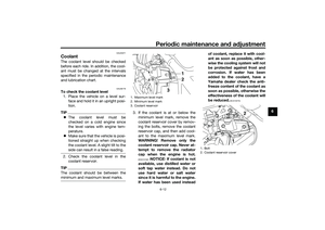
falling over.1. Loosen the axle nut and the brake
caliper bolts.2. Lift the front wheel off the ground
according to the procedure in the
previous section “Supporting the
motorcycle”.
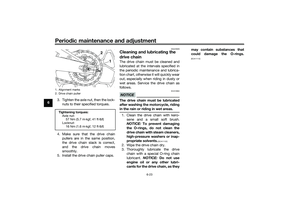
3. Remove the brake caliper (togeth-
er with the reflector on each side)
by removing the bolts. NOTICE:
Do not apply the brake after the
brake caliper has been re-
moved, otherwise the brake
pads will be forced shut.
[ECA22240]
4. Remove the axle nut.
5. Pull the wheel axle out, and then
remove the wheel.
To install the front wheel
1. Lift the wheel up between the fork
legs.2. Insert the wheel axle from the right
side and then install the axle nut.
3. Install the brake caliper (together
with the reflectors on each side)
by installing the bolts.
TIPMake sure that there is enough space
between the brake pads before install-
ing the brake caliper onto the brake
disc.4. Lower the front wheel so that it is
on the ground, and then put the
sidestand down.
5. Tighten the wheel axle and the
brake caliper bolts to the specified
torques.
6. Push down hard on the handlebar
several times to check for proper
fork operation.
1. Axle nut
1
1. Brake caliper bolt
1
Tightening torques:
Wheel axle:
60 Nm (6.0 m·kgf, 44 ft·lbf)
Brake caliper bolt:
35 Nm (3.5 m·kgf, 25 ft·lbf)
UB04E0E0.book Page 34 Wednesday, September 2, 2015 3:51 PM
Page 78 of 96

Periodic maintenance and adjustment
6-35
6
EAU25081
Rear wheel
EAU62612
To remove the rear wheel
WARNING
EWA10822
To avoid injury, securely support the
vehicle so there is no danger of it
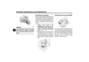
falling over.1. Remove the drive chain puller cap,
and then loosen the locknut and
drive chain slack adjusting nut on
each side of the swingarm.2. Loosen the axle nut.
3. Lift the rear wheel off the ground
according to the procedure on
page 6-33.
4. Remove the axle nut.
5. Push the wheel forward, and then
remove the drive chain from the
rear sprocket.
TIPThe drive chain does not need to be
disassembled in order to remove and
install the rear wheel.6. While supporting the brake caliper
and slightly lifting the wheel, pull
the wheel axle out.TIPA rubber mallet may be useful to tap
the wheel axle out.7. Remove the wheel. NOTICE: Do
not apply the brake after the
wheel and brake disc have been
removed, otherwise the brake
pads will be forced shut.
[ECA11073]
1. Wheel axle
2. Drive chain slack adjusting nut
3. Locknut
4. Drive chain puller cap
342
1
1. Axle nut
1
1. Wheel axle
2. Washer
1 2
UB04E0E0.book Page 35 Wednesday, September 2, 2015 3:51 PM
Page 79 of 96

Periodic maintenance and adjustment
6-36
6 To install the rear wheel
1. Install the wheel and the brake cal-
iper bracket by inserting the wheel
axle from the left-hand side.
TIPMake sure that the slot in the
brake caliper bracket is fit over the
retainer on the swingarm.
Make sure that there is enough
space between the brake pads
before installing the wheel.2. Install the drive chain onto the rear
sprocket.
3. Install the axle nut.4. Lower the rear wheel so that it is
on the ground, and then put the
sidestand down.
5. Adjust the drive chain slack. (See
page 6-21.)
6. Tighten the axle nut, and then
tighten the locknuts to the speci-
fied torques.
7. Install the drive chain puller caps.
EAU25872
TroubleshootingAlthough Yamaha motorcycles receive
a thorough inspection before shipment
from the factory, trouble may occur
during operation. Any problem in the
fuel, compression, or ignition systems,
for example, can cause poor starting
and loss of power.
The following troubleshooting charts
represent quick and easy procedures
for checking these vital systems your-
self. However, should your motorcycle
require any repair, take it to a Yamaha
dealer, whose skilled technicians have
the necessary tools, experience, and
know-how to service the motorcycle
properly.
Use only genuine Yamaha replace-
ment parts. Imitation parts may look
like Yamaha parts, but they are often
inferior, have a shorter service life and
can lead to expensive repair bills.
WARNING
EWA15142
When checking the fuel system, do
not smoke, and make sure there are
no open flames or sparks in the ar-
ea, including pilot lights from water
1. Retainer
2. Slot
1
2
Tightening torques:
Axle nut:
57 Nm (5.7 m·kgf, 41 ft·lbf)
Locknut:
16 Nm (1.6 m·kgf, 12 ft·lbf)
UB04E0E0.book Page 36 Wednesday, September 2, 2015 3:51 PM
Page 80 of 96
Periodic maintenance and adjustment
6-37
6heaters or furnaces. Gasoline or
gasoline vapors can ignite or ex-
plode, causing severe injury or prop-
erty damage.
UB04E0E0.book Page 37 Wednesday, September 2, 2015 3:51 PM


 by turning it clockwise.")
