Page 65 of 96

Periodic maintenance and adjustment
6-22
6 4. If the drive chain slack is incorrect,
adjust it as follows.
EAU62982
To adjust the drive chain slack
Consult a Yamaha dealer before ad-
justing the drive chain slack.
1. Remove the drive chain puller cap,
and then loosen the axle nut and
the locknut on each side of the
swingarm.
2. To tighten the drive chain, turn the
drive chain slack adjusting nut on
each side of the swingarm in di-
rection (a). To loosen the drive
chain, turn the adjusting nut on
each side of the swingarm in di-rection (b), and then push the rear
wheel forward. NOTICE: Improp-
er drive chain slack will over-
load the engine as well as other
vital parts of the motorcycle and
can lead to chain slippage or
breakage. To prevent this from
occurring, keep the drive chain
slack within the specified limits.
[ECA10572]
TIPUsing the alignment marks on each
side of the swingarm, make sure that
both drive chain pullers are in the same
position for proper wheel alignment.
1. Drive chain slack
1
1. Locknut
2. Drive chain puller cap
1. Axle nut
12
1
1. Drive chain slack adjusting nut
1
(a)(b)
UB04E0E0.book Page 22 Wednesday, September 2, 2015 3:51 PM
Page 66 of 96

Periodic maintenance and adjustment
6-23
63. Tighten the axle nut, then the lock-
nuts to their specified torques.
4. Make sure that the drive chain
pullers are in the same position,
the drive chain slack is correct,
and the drive chain moves
smoothly.
5. Install the drive chain puller caps.
EAU23026
Cleaning and lubricating the
drive chainThe drive chain must be cleaned and
lubricated at the intervals specified in
the periodic maintenance and lubrica-
tion chart, otherwise it will quickly wear
out, especially when riding in dusty or
wet areas. Service the drive chain as
follows.NOTICE
ECA10584
The drive chain must be lubricated
after washing the motorcycle, riding
in the rain or riding in wet areas.1. Clean the drive chain with kero-
sene and a small soft brush.
NOTICE: To prevent damaging
the O-rings, do not clean the
drive chain with steam cleaners,
high-pressure washers or inap-
propriate solvents.
[ECA11122]
2. Wipe the drive chain dry.
3. Thoroughly lubricate the drive
chain with a special O-ring chain
lubricant. NOTICE: Do not use
engine oil or any other lubri-
cants for the drive chain, as theymay contain substances that
could damage the O-rings.
[ECA11112]
1. Alignment marks
2. Drive chain pullerTightening torques:
Axle nut:
57 Nm (5.7 m·kgf, 41 ft·lbf)
Locknut:
16 Nm (1.6 m·kgf, 12 ft·lbf)
1 2
UB04E0E0.book Page 23 Wednesday, September 2, 2015 3:51 PM
Page 67 of 96

Periodic maintenance and adjustment
6-24
6
EAU23098
Checking and lubricating the
cablesThe operation of all control cables and
the condition of the cables should be
checked before each ride, and the ca-
bles and cable ends should be lubri-
cated if necessary. If a cable is
damaged or does not move smoothly,
have a Yamaha dealer check or re-
place it. WARNING! Damage to the
outer housing of cables may result
in internal rusting and cause inter-
ference with cable movement. Re-
place damaged cables as soon as
possible to prevent unsafe condi-
tions.
[EWA10712]EAU49921
Checking and lubricating the
throttle grip and cableThe operation of the throttle grip
should be checked before each ride. In
addition, the cable should be lubricat-
ed by a Yamaha dealer at the intervals
specified in the periodic maintenance
chart.
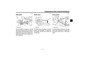
EAU44276
Checking and lubricating the
brake and shift pedalsThe operation of the brake and shift
pedals should be checked before each
ride, and the pedal pivots should be lu-
bricated if necessary.
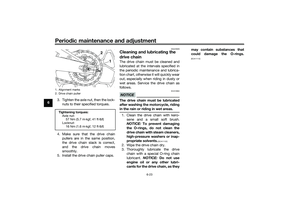
Brake pedal
Shift pedal
Recommended lubricant:
Yamaha cable lubricant or other
suitable cable lubricant
UB04E0E0.book Page 24 Wednesday, September 2, 2015 3:51 PM
Page 68 of 96
Periodic maintenance and adjustment
6-25
6
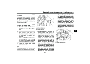
EAU23144
Checking and lubricating the
brake and clutch leversThe operation of the brake and clutch
levers should be checked before each
ride, and the lever pivots should be lu-
bricated if necessary.
Brake lever
Clutch lever
Recommended lubricant:
Lithium-soap-based grease
Recommended lubricants:
Brake lever:
Silicone grease
Clutch lever:
Lithium-soap-based grease
UB04E0E0.book Page 25 Wednesday, September 2, 2015 3:51 PM
Page 69 of 96

Periodic maintenance and adjustment
6-26
6
EAU23203
Checking and lubricating the
sidestandThe operation of the sidestand should
be checked before each ride, and the
sidestand pivot and metal-to-metal
contact surfaces should be lubricated
if necessary.
WARNING
EWA10732
If the sidestand does not move up
and down smoothly, have a Yamaha
dealer check or repair it. Otherwise,
the sidestand could contact the
ground and distract the operator, re-
sulting in a possible loss of control.
EAUM1653
Lubricating the swingarm piv-
otsThe swingarm pivots must be lubricat-
ed by a Yamaha dealer at the intervals
specified in the periodic maintenance
and lubrication chart.
EAU23273
Checking the front forkThe condition and operation of the
front fork must be checked as follows
at the intervals specified in the periodic
maintenance and lubrication chart.
To check the condition
Check the inner tubes for scratches,
damage and excessive oil leakage.
To check the operation
1. Place the vehicle on a level sur-
face and hold it in an upright posi-
tion. WARNING! To avoid injury,
securely support the vehicle so
there is no danger of it falling
over.
[EWA10752]
2. While applying the front brake,
push down hard on the handle-
bars several times to check if the
front fork compresses and re-
bounds smoothly.
Recommended lubricant:
Lithium-soap-based grease
Recommended lubricant:
Lithium-soap-based grease
UB04E0E0.book Page 26 Wednesday, September 2, 2015 3:51 PM
Page 70 of 96

Periodic maintenance and adjustment
6-27
6
NOTICE
ECA10591
If any damage is found or the front
fork does not operate smoothly,
have a Yamaha dealer check or re-
pair it.
EAU23285
Checking the steeringWorn or loose steering bearings may
cause danger. Therefore, the operation
of the steering must be checked as fol-
lows at the intervals specified in the
periodic maintenance and lubrication
chart.
1. Raise the front wheel off the
ground. (See page 6-33.)
WARNING! To avoid injury, se-
curely support the vehicle so
there is no danger of it falling
over.
[EWA10752]
2. Hold the lower ends of the front
fork legs and try to move them for-
ward and backward. If any free
play can be felt, have a Yamaha
dealer check or repair the steer-
ing.
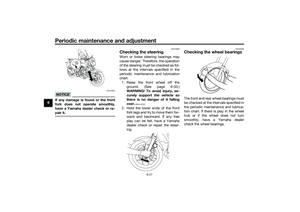
EAU23292
Checking the wheel bearingsThe front and rear wheel bearings must
be checked at the intervals specified in
the periodic maintenance and lubrica-
tion chart. If there is play in the wheel
hub or if the wheel does not turn
smoothly, have a Yamaha dealer
check the wheel bearings.
UB04E0E0.book Page 27 Wednesday, September 2, 2015 3:51 PM
Page 71 of 96

This model is equipped with a VRLA
(Valve Regulated Lead Acid) battery.
There i")
Periodic maintenance and adjustment
6-28
6
EAU62521
BatteryThe battery is located under the rider
seat. (See page 3-16.)
This model is equipped with a VRLA
(Valve Regulated Lead Acid) battery.
There is no need to check the electro-
lyte or to add distilled water. However,
the battery lead connections need to
be checked and, if necessary, tight-
ened.
WARNING
EWA10761
Electrolyte is poisonous and
dangerous since it contains sul-
furic acid, which causes severeburns. Avoid any contact with
skin, eyes or clothing and al-
ways shield your eyes when
working near batteries. In case
of contact, administer the fol-
lowing FIRST AID.
EXTERNAL: Flush with plenty
of water.
INTERNAL: Drink large quan-
tities of water or milk and im-
mediately call a physician.
EYES: Flush with water for 15
minutes and seek prompt
medical attention.
Batteries produce explosive hy-
drogen gas. Therefore, keep
sparks, flames, cigarettes, etc.,
away from the battery and pro-
vide sufficient ventilation when
charging it in an enclosed
space.
KEEP THIS AND ALL BATTER-
IES OUT OF THE REACH OF
CHILDREN.
NOTICE
ECA10621
Never attempt to remove the battery
cell seals, as this would permanently
damage the battery.To charge the battery
Have a Yamaha dealer charge the bat-
tery as soon as possible if it seems to
have discharged. Keep in mind that the
battery tends to discharge more quick-
ly if the vehicle is equipped with op-
tional electrical accessories.NOTICE
ECA16522
To charge a VRLA (Valve Regulated
Lead Acid) battery, a special (con-
stant-voltage) battery charger is re-
quired. Using a conventional battery
charger will damage the battery.To store the battery
1. If the vehicle will not be used for
more than one month, remove the
battery, fully charge it, and then
place it in a cool, dry place.
NOTICE: When removing the
battery, be sure the key is
1. Battery
2. Negative battery lead (black)
3. Positive battery lead (red)
1
2
3
UB04E0E0.book Page 28 Wednesday, September 2, 2015 3:51 PM
Page 72 of 96
![YAMAHA MT-25 2016 Owners Manual Periodic maintenance and adjustment
6-29
6turned to “ ”, then disconnect
the negative lead before discon-
necting the positive lead.
[ECA17712]
2. If the battery will be stored for
more than two](/manual-img/51/50981/w960_50981-71.png "YAMAHA MT-25 2016 Owners Manual Periodic maintenance and adjustment
6-29
6turned to “ ”, then disconnect
the negative lead before discon-
necting the positive lead.
[ECA17712]
2. If the battery will be stored for
more than two")
Periodic maintenance and adjustment
6-29
6turned to “ ”, then disconnect
the negative lead before discon-
necting the positive lead.
[ECA17712]
2. If the battery will be stored for
more than two months, check it at
least once a month and fully
charge it if necessary.
3. Fully charge the battery before in-
stallation. NOTICE: When install-
ing the battery, be sure the key
is turned to “ ”, then connect
the positive lead before con-
necting the negative lead.
[ECA17722]
4. After installation, make sure that
the battery leads are properly con-
nected to the battery terminals.NOTICE
ECA16531
Always keep the battery charged.
Storing a discharged battery can
cause permanent battery damage.
EAU62773
Replacing the fusesThe main fuse is located under the
passenger seat. The fuse box, which
contains the fuses for the individual cir-
cuits, is located behind the center pan-
el. (See page 3-16.)
To access the main fuse, proceed as
follows.
1. Remove the passenger seat. (See
page 3-16.)
2. Remove the tray by removing the
quick fasteners.
3. Pull back the starter relay cover.4. Disconnect the starter relay cou-
pler by pressing from both sides.
5. Connect the starter relay coupler,
and then slide the cover to its orig-
inal position.
6. Place the tray in its original posi-
tion, and then install the quick fas-
teners.
7. Install the passenger seat.
TIPTo access the fuse box, remove the
center cover. (See page 3-16.)
1. Quick fastener
2. Tray
21
1. Starter relay cover
2. Starter relay coupler
3. Main fuse
4. Spare main fuse
1
2
34
UB04E0E0.book Page 29 Wednesday, September 2, 2015 3:51 PM