Page 33 of 96

When storing documents or other
items in the storage c")
Instrument and control functions
3-18
3
EAU62550
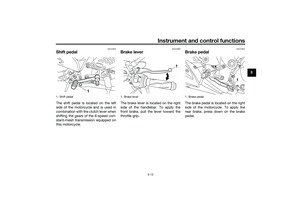
Storage compartmentThe storage compartment is located
under the passenger seat. (See page
3-16.)
When storing documents or other
items in the storage compartment, be
sure to wrap them in a plastic bag so
that they will not get wet. When wash-
ing the vehicle, be careful not to let any
water enter the storage compartment.
WARNING
EWA15401
Do not exceed the maximum load of
160 kg (353 lb) for the vehicle.
EAU62561
Adjusting the shock absorber
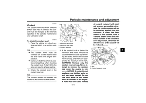
assemblyThis shock absorber assembly is
equipped with a spring preload adjust-
ing ring.NOTICE
ECA10102
To avoid damaging the mechanism,
do not attempt to turn beyond the
maximum or minimum settings.Adjust the spring preload as follows.
To increase the spring preload and
thereby harden the suspension, turn
the adjusting ring in direction (a). To
decrease the spring preload and there-
by soften the suspension, turn the ad-
justing ring in direction (b).
Align the appropriate notch in the
adjusting ring with the position in-
dicator on the shock absorber.
Use the special wrench and the
extension bar included in the own-
er’s tool kit to make the adjust-
ment.
1. Storage compartment
1
1. Extension bar
2. Special wrench
3. Spring preload adjusting ring
4. Position indicator
Spring preload setting:
Minimum (soft):
1
Standard:
3
Maximum (hard):
77654321
2
1
3
4
(b)
(a)
UB04E0E0.book Page 18 Wednesday, September 2, 2015 3:51 PM
Page 34 of 96

Instrument and control functions
3-19
3
EAU15152
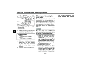
Luggage strap holdersThere is a luggage strap holder on
each passenger footrest.
EAU15306
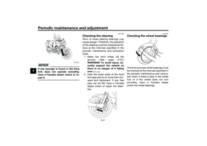
SidestandThe sidestand is located on the left
side of the frame. Raise the sidestand
or lower it with your foot while holding
the vehicle upright.TIPThe built-in sidestand switch is part of
the ignition circuit cut-off system,
which cuts the ignition in certain situa-
tions. (See the following section for an
explanation of the ignition circuit cut-
off system.)
WARNING
EWA10242
The vehicle must not be ridden with
the sidestand down, or if the side-
stand cannot be properly moved up
(or does not stay up), otherwise the
sidestand could contact the ground
and distract the operator, resulting
in a possible loss of control.
Yamaha’s ignition circuit cut-off
system has been designed to assist
the operator in fulfilling the respon-
sibility of raising the sidestand be-
fore starting off. Therefore, checkthis system regularly and have a
Yamaha dealer repair it if it does not
function properly.
1. Luggage strap holder
1
UB04E0E0.book Page 19 Wednesday, September 2, 2015 3:51 PM
Page 35 of 96
Instrument and control functions
3-20
3
EAU44893
Ignition circuit cut-off systemThe ignition circuit cut-off system
(comprising the sidestand switch,
clutch switch and neutral switch) has
the following functions.
It prevents starting when the
transmission is in gear and the
sidestand is up, but the clutch le-
ver is not pulled.
It prevents starting when the
transmission is in gear and the
clutch lever is pulled, but the side-
stand is still down.
It cuts the running engine when
the transmission is in gear and the
sidestand is moved down.
Periodically check the operation of the
ignition circuit cut-off system accord-
ing to the following procedure.
UB04E0E0.book Page 20 Wednesday, September 2, 2015 3:51 PM
Page 36 of 96

Instrument and control functions
3-21
3
With the engine turned off:
1. Move the sidestand down.
2. Make sure that the engine stop switch is set to “
3. Turn the key on.
4. Shift the transmission into the neutral position.
5. Push the start switch.
Does the engine start?
With the engine still running:
6. Move the sidestand up.
7. Keep the clutch lever pulled.
8. Shift the transmission into gear.
9. Move the sidestand down.
Does the engine stall?
After the engine has stalled:
10. Move the sidestand up.
11. Keep the clutch lever pulled.
12. Push the start switch.
Does the engine start?
The system is OK. The motorcycle can be ridden.The neutral switch may not be working correctly.
The motorcycle should not be ridden until
checked by a Yamaha dealer.
The sidestand switch may not be working correctly.
The motorcycle should not be ridden until
checked by a Yamaha dealer.
The clutch switch may not be working correctly.
The motorcycle should not be ridden until
checked by a Yamaha dealer.
YES NO YES NO YES NO
If a malfunction is noted, have a Yamaha
dealer check the system before riding.
WARNING
”.
UB04E0E0.book Page 21 Wednesday, September 2, 2015 3:51 PM
Page 37 of 96

For your safety – pre-operation checks
4-1
4
EAU15599
Inspect your vehicle each time you use it to make sure the vehicle is in safe operating condition. Always follow the inspection
and maintenance procedures and schedules described in the Owner’s Manual.
WARNING
EWA11152
Failure to inspect or maintain the vehicle properly increases the possibility of an accident or equipment damage.
Do not operate the vehicle if you find any problem. If a problem cannot be corrected by the procedures provided in
this manual, have the vehicle inspected by a Yamaha dealer.Before using this vehicle, check the following points:
ITEM CHECKS PAGE
Fuel• Check fuel level in fuel tank.
• Refuel if necessary.
• Check fuel line for leakage.
• Check fuel tank breather hose and overflow hose for obstructions, cracks or
damage, and check hose connections.3-13, 3-15
Engine oil• Check oil level in engine.
• If necessary, add recommended oil to specified level.
• Check vehicle for oil leakage.6-9
Coolant• Check coolant level in reservoir.
• If necessary, add recommended coolant to specified level.
• Check cooling system for leakage.6-12
Front brake• Check operation.
• If soft or spongy, have Yamaha dealer bleed hydraulic system.
• Check brake pads for wear.
• Replace if necessary.
• Check fluid level in reservoir.
• If necessary, add specified brake fluid to specified level.
• Check hydraulic system for leakage.6-19, 6-20
UB04E0E0.book Page 1 Wednesday, September 2, 2015 3:51 PM
Page 38 of 96

For your safety – pre-operation checks
4-2
4
Rear brake• Check operation.
• If soft or spongy, have Yamaha dealer bleed hydraulic system.
• Check brake pads for wear.
• Replace if necessary.
• Check fluid level in reservoir.
• If necessary, add specified brake fluid to specified level.
• Check hydraulic system for leakage.6-19, 6-20
Clutch• Check operation.
• Lubricate cable if necessary.
• Check lever free play.
• Adjust if necessary.6-17
Throttle grip• Make sure that operation is smooth.
• Check throttle grip free play.
• If necessary, have Yamaha dealer adjust throttle grip free play and lubricate ca-
ble and grip housing.6-15, 6-24
Control cables• Make sure that operation is smooth.
• Lubricate if necessary.6-24
Drive chain• Check chain slack.
• Adjust if necessary.
• Check chain condition.
• Lubricate if necessary.6-21, 6-23
Wheels and tires•Check for damage.
• Check tire condition and tread depth.
• Check air pressure.
• Correct if necessary.6-15, 6-17
Brake and shift pedals• Make sure that operation is smooth.
• Lubricate pedal pivoting points if necessary.6-24
Brake and clutch levers• Make sure that operation is smooth.
• Lubricate lever pivoting points if necessary.6-25
Sidestand• Make sure that operation is smooth.
• Lubricate pivot if necessary.6-26 ITEM CHECKS PAGE
UB04E0E0.book Page 2 Wednesday, September 2, 2015 3:51 PM
Page 39 of 96
For your safety – pre-operation checks
4-3
4
Chassis fasteners• Make sure that all nuts, bolts and screws are properly tightened.
• Tighten if necessary.—
Instruments, lights, signals
and switches• Check operation.
• Correct if necessary.—
Sidestand switch • Check operation of ignition circuit cut-off system.
• If system is not working correctly, have Yamaha dealer check vehicle.3-19 ITEM CHECKS PAGE
UB04E0E0.book Page 3 Wednesday, September 2, 2015 3:51 PM
Page 40 of 96

Operation and important riding points
5-1
5
EAU15952
Read the Owner’s Manual carefully to
become familiar with all controls. If
there is a control or function you do not
understand, ask your Yamaha dealer.
WARNING
EWA10272
Failure to familiarize yourself with
the controls can lead to loss of con-
trol, which could cause an accident
or injury.
EAU62513
TIPThis model is equipped with:
a lean angle sensor to stop the en-
gine in case of a turnover. In this
case, the display will indicate error
code 30, but this is not a malfunc-
tion. Turn the key to “ ” and then
to “ ” to clear the error code.
Failing to do so will prevent the en-
gine from starting even though the
engine will crank when pushing
the start switch.
an engine auto-stop system. The
engine stops automatically if left
idling for 20 minutes. If the engine
stops, simply push the start
switch to restart the engine.
EAUN0680
Starting the engineIn order for the ignition circuit cut-off
system to enable starting, one of the
following conditions must be met:
The transmission is in the neutral
position.
The transmission is in gear with
the clutch lever pulled and the
sidestand up.
See page 3-20 for more informa-
tion.
1. Turn the key to “ ” and make
sure that the engine stop switch is
set to “ ”.
The engine trouble warning light
should come on for a few sec-
onds, then go off. NOTICE: If the
warning light does not go off,
have a Yamaha dealer check its
electrical circuit.
[ECAT1121]
2. Shift the transmission into the
neutral position. The neutral indi-
cator light should come on. If not,
ask a Yamaha dealer to check the
electrical circuit.
3. Start the engine by pushing the
start switch.
UB04E0E0.book Page 1 Wednesday, September 2, 2015 3:51 PM


 has
the followin")
