Page 17 of 96

Instrument and control functions
3-2
3 To unlock the steering
1. Insert the key.
2. With the key in the “LOCK” posi-
tion, push the key in and turn it
to “ ”.
EAU49398
Indicator lights and warning
lights
EAU11022
Turn signal indicator light “ ”
This indicator light flashes when a turn
signal light is flashing.
EAU11061
Neutral indicator light “ ”
This indicator light comes on when the
transmission is in the neutral position.
EAU11081
High beam indicator light “ ”
This indicator light comes on when the
high beam of the headlight is switched
on.
EAU62530
Oil pressure warning light “ ”
This warning light comes on if the en-
gine oil pressure is low.
The electrical circuit of the warning
light can be checked by turning the key
to “ ”. The warning light should come
on and remain on until the engine is
started.
If the warning light does not come on
initially when the key is turned to “ ”,
have a Yamaha dealer check the elec-
trical circuit.NOTICE
ECA21210
If the warning light comes on when
the engine is running, stop the en-
gine immediately and check oil level.
If the oil level is below the minimum
level, add sufficient oil of the recom-
mended t y p e t o r a i s e i t u p t o t h e c o r -
rect level. If the oil pressure warning
light remains on even if the oil level
1. Push.
2. Turn.12
1. Neutral indicator light Ž
2. High beam indicator light Ž
3. Turn signal indicator light Ž
4. Shift timing indicator light
5. Oil pressure warning light Ž
6. Engine trouble warning light Ž
6
5
3
1
2
4
UB04E0E0.book Page 2 Wednesday, September 2, 2015 3:51 PM
Page 18 of 96

Instrument and control functions
3-3
3is correct, immediately turn the en-
gine off and have a Yamaha dealer
check the vehicle.
TIPIf the warning light does not go off after
starting the engine, check the engine
oil level and add oil if necessary. (See
page 6-9.)
If the warning light remains on after
adding engine oil, have a Yamaha
dealer check the vehicle.
EAU62790
Engine trouble warning light “ ”
This warning light comes on or flashes
if a problem is detected in the electrical
circuit monitoring the engine. If this oc-
curs, have a Yamaha dealer check the
self-diagnosis system. (See page 3-10
for an explanation of the self-diagnosis
device.)
The electrical circuit of the warning
light can be checked by turning the key
to “ ”. The warning light should come
on for a few seconds, and then go off.If the warning light does not come on
initially when the key is turned to “ ”,
or if the warning light remains on, have
a Yamaha dealer check the electrical
circuit.
TIPThe engine trouble warning light will
come on while the start switch is
pushed, but this does not indicate a
malfunction.
EAU62470
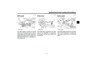
Shift timing indicator light
This indicator light can be set to come
on and go off at the desired engine
speeds and is used to inform the rider
when it is time to shift to the next high-
er gear. (See page 3-8 for a more de-
tailed explanation of this indicator light
and on how to set it.)
The electrical circuit of the indicator
light can be checked by turning the key
to “ ”. The indicator light should
come on for a few seconds, and then
go off.If the indicator light does not come on
initially when the key is turned to “ ”,
or if the indicator light remains on, have
a Yamaha dealer check the electrical
circuit.
UB04E0E0.book Page 3 Wednesday, September 2, 2015 3:51 PM
Page 19 of 96

Instrument and control functions
3-4
3
EAU62765
Multi-function meter unit
WARNING
EWA12423
Be sure to stop the vehicle before
making any setting changes to the
multi-function meter unit. Changingsettings while riding can distract the
operator and increase the risk of an
accident.
The multi-function meter unit is
equipped with the following:
a speedometer
a tachometer
a clock
a fuel meter
a coolant temperature meter
a transmission gear display
a multi-function display
a shift timing indicator light
a self-diagnosis deviceTIPBe sure to turn the key to Ž before
except for setting the shift timing indi-
cator light control mode.Speedometer
The speedometer shows the vehicle’s
traveling speed.Tachometer
The tachometer allows the rider to
monitor the engine speed and keep it
within the ideal power range.
When the key is turned to “ ”, the ta-
chometer will sweep across the r/min
range and then return to zero r/min in
order to test the electrical circuit.
NOTICE
ECA10032
Do not operate the engine in the ta-
chometer red zone.
Red zone: 14000 r/min and above
1. “SEL” button
2. “RES” button
3. Tachometer
4. Fuel meter
5. Shift timing indicator light
6. Clock
7. Transmission gear display
8. Speedometer
9. Multi-function display
10.Coolant temperature meter
10
9
1
3
2
4
6
5
7
8
1. Tachometer
2. Tachometer red zone
12
UB04E0E0.book Page 4 Wednesday, September 2, 2015 3:51 PM
Page 20 of 96

Instrument and control functions
3-5
3Clock
The clock displays when the key is
turned to “ ”.
To set the clock
1. Turn the key to “ ”.
2. Push the “SEL” button and “RES”
button together for at least two
seconds.
3. When the hour digits start flash-
ing, push the “RES” button to set
the hours.
4. Push the “SEL” button, and the
minute digits will start flashing.
5. Push the “RES” button to set the
minutes.
6. Push the “SEL” button and then
release it to start the clock.Fuel meter
The fuel meter indicates the amount of
fuel in the fuel tank.
When the key is turned to “ ”, the dis-
play segments of the fuel meter will
sweep once across the fuel level range
and then return to the current amount
in order to test the electrical circuit.
The display segments of the fuel meter
disappear towards “E” (Empty) as the
fuel level decreases. When the last
segment starts flashing, refuel as soon
as possible.
TIPThis fuel meter is equipped with a self-
diagnosis system. If a problem is de-
tected in the electrical circuit, the fol-lowing cycle is repeated until the
malfunction is corrected: fuel level seg-
ments flash eight times, then go off for
approximately three seconds. If this
occurs, have a Yamaha dealer check
the electrical circuit.
Coolant temperature meter
The coolant temperature meter indi-
cates the temperature of the coolant.
When the key is turned to “ ”, the dis-
play segments of the digital coolant
temperature gauge will sweep once
across the temperature range and then
return to “C” in order to test the electri-
cal circuit.
1. Clock
1
1. Fuel meter
1
1. Coolant temperature meter
1
UB04E0E0.book Page 5 Wednesday, September 2, 2015 3:51 PM
Page 21 of 96

NOTICE
ECA10022
Do not continue to op")
Instrument and control functions
3-6
3 If the last segment on the right flashes,
stop the vehicle, then stop the engine,
and let the engine cool. (See page
6-39.)
NOTICE
ECA10022
Do not continue to operate the en-
gine if it is overheating.TIPThe coolant temperature varies with
changes in the weather and engine
load.Transmission gear displayThis display shows the selected gear.
The neutral position is indicated by “ ”
and by the neutral indicator light.
Multi-function display
The multi-function display is equipped
with the following:
an odometer
two tripmeters
a fuel reserve tripmeter
an instantaneous fuel consump-
tion display
an average fuel consumption dis-
play
an oil change tripmeter
an oil change indicator
The odometer shows the total distance
traveled by the vehicle.The tripmeters show the distance trav-
eled since they were last set to zero.
Push the “SEL” button to switch the
display between the odometer mode
“ODO”, tripmeter modes “TRIP 1” and
“TRIP 2”, instantaneous fuel consump-
tion mode “km/L” or “L/100 km”, aver-
age fuel consumption mode “AVE_ _._
km/L” or “AVE_ _._ L/100 km” and oil
change tripmeter mode “OIL TRIP” in
the following order:
ODO → TRIP 1 → TRIP 2 → km/L or
L/100 km → AVE_ _._ km/L or AVE_ _._
L/100 km → OIL TRIP → ODO
The fuel reserve tripmeter shows the
distance traveled since the fuel level
warning light came on.
If the left segment of the fuel meter
starts flashing, the display automati-
cally changes to the fuel reserve trip-
meter mode “TRIP F” and starts
counting the distance traveled from
that point. In that case, push the “SEL”
button to switch the display between
the various tripmeter, odometer, in-1. Neutral indicator light “ ”
2. Transmission gear display
1
2
1. Multi-function display
1
UB04E0E0.book Page 6 Wednesday, September 2, 2015 3:51 PM
Page 22 of 96

Instrument and control functions
3-7
3stantaneous fuel consumption and av-
erage fuel consumption modes in the
following order:
TRIP F → km/L or L/100 km → AVE_
_._ km/L or AVE_ _._ L/100 km → OIL
TRIP → ODO → TRIP 1 → TRIP 2 →
TRIP F
To reset a tripmeter, select it by push-
ing the “SEL” button, and then push
the “RES” button for at least one sec-
ond.
If you do not reset the fuel reserve trip-
meter manually, it resets itself auto-
matically and the display returns to the
prior mode after refueling and traveling
5 km (3 mi).
TIPThe odometer will lock at 999999.
The tripmeters will reset and con-
tinue counting after 9999.9 is
reached.
Instantaneous fuel consumption
display
The instantaneous fuel consumption
display can be set to either “km/L” or
“L/100 km”.
“km/L”: The distance that can be
traveled on 1.0 L of fuel under the
current riding conditions is shown.
“L/100 km”: The amount of fuel
necessary to travel 100 km under
the current riding conditions is
shown.
To switch between the instantaneous
fuel consumption displays, push the
“SEL” button for one second.
TIPIf traveling at speeds under 20 km/h
Average fuel consumption display
The average fuel consumption display
can be set to either “AVE_ _._ km/L” or
“AVE_ _._ L/100 km”.
This display shows the average fuel
consumption since it was last reset.
“AVE_ _._ km/L”: The average dis-
tance that can be traveled on 1.0 L
of fuel is shown.
“AVE_ _._ L/100 km”: The average
amount of fuel necessary to travel
100 km is shown.
1. Instantaneous fuel consumption display
1
1. Average fuel consumption display
1
UB04E0E0.book Page 7 Wednesday, September 2, 2015 3:51 PM
Page 23 of 96

Instrument and control functions
3-8
3 To switch between the average fuel
consumption displays, push the “SEL”
button for one second.
To reset the average fuel consumption
display, push the “RES” button for at
least one second.
TIPAfter resetting the average fuel con-
the vehicle has traveled 1 km (0.6 mi).Oil change tripmeter
The oil change tripmeter shows the
distance traveled since it was last reset
(i.e., since the last oil change).The oil change indicator “OIL” will flash
at the initial 1000 km (600 mi), then at
5000 km (3000 mi) and every 5000 km
(3000 mi) thereafter to indicate that the
engine oil should be changed.
After changing the engine oil, reset the
oil change tripmeter and the oil change
indicator. To reset them both, select
the oil change tripmeter, and then push
the “RES” button for one second.
Then, while “OIL” and the oil change
tripmeter are flashing, push the “RES”
button for three seconds. The oil
change indicator will be reset.
If the engine oil is changed before the
oil change indicator comes on (i.e., be-
fore the periodic oil change interval has
been reached), the oil change tripmeter
must be reset for the next periodic oil
change to be indicated at the correct
time.Shift timing indicator light
The shift timing indicator light has four
settings which can be adjusted.
Flashing pattern: this function al-
lows you to choose whether or not
the indicator light will come on and
whether it should flash or stay on
when activated.
Activation point: this function al-
lows you to select the engine
speed at which the indicator light
is activated.
Deactivation point: this function
allows you to select the engine
speed at which the indicator light
is deactivated.1. Oil change indicator “OIL”
2. Oil change tripmeter
2
1
1. Shift timing indicator light
2. Brightness level display
1
2
UB04E0E0.book Page 8 Wednesday, September 2, 2015 3:51 PM
Page 24 of 96

Instrument and control functions
3-9
3Brightness: this function allows
you to adjust the brightness of the
indicator light.
To adjust the shift timing indicator light
1. Turn the key to “ ”.
2. Push and hold the “SEL” button.
3. Turn the key to “ ”, and then re-
lease the “SEL” button after five
seconds. The shift timing indicator
light can now be adjusted.
To set the flashing pattern1. Push the “RES” button to select
one of the following flashing pat-
tern settings:
On: the indicator light stays
on when activated. (This set-
ting is selected when the indi-
cator light stays on.)
Flash: the indicator light
flashes when activated. (This
setting is selected when the
indicator light flashes four
times per second.)
Off: the indicator light is deac-
tivated; in other words, it
does not come on or flash.(This setting is selected when
the indicator light flashes
once every two seconds.)
2. Push the “SEL” button to confirm
the selected flashing pattern. The
shift timing indicator light changes
to the activation point setting
mode.
The tachometer will show the current
setting r/min for the activation point
and deactivation point setting modes.
To set the shift activation point
TIPThe shift timing indicator light activa-
tion point can be set between 7000
r/min and 15000 r/min. From 7000
r/min to 12000 r/min, the indicator light
can be set in increments of 500 r/min.
From 12000 r/min to 15000 r/min, the
indicator light can be set in increments
of 200 r/min.1.
the desired engine speed for acti-
vating the indicator light.2.
the selected engine speed. The
control mode changes to the de-
activation point setting mode.
To set the deactivation point
TIPThe shift timing indicator light de-
activation point can be set be-
tween 7000 r/min and 15000
r/min. From 7000 r/min to 12000
r/min, the indicator light can be set
in increments of 500 r/min. From
12000 r/min to 15000 r/min, the in-
dicator light can be set in incre-
ments of 200 r/min.
Be sure to set the deactivation
point to a higher engine speed
than for the activation point, other-
wise the shift timing indicator light
will not come on.1. Push the “RES” button to select
the desired engine speed for de-
activating the indicator light.
2. Push the “SEL” button to confirm
the selected engine speed. The
control mode changes to the
brightness setting mode.
UB04E0E0.book Page 9 Wednesday, September 2, 2015 3:51 PM