Page 137 of 248

Transport and practical equipment
Rear shelf Fig. 149
Rear shelf. Removing the shelf
–
Unhook the loops ››
› Fig. 149 B from
hou s
in
gs A .
– Extract the cover from its slot, in its rest po-
sition and p
u
ll outwards. WARNING
Do not place heavy or hard objects on the
re ar shelf
, because they will endanger the ve-
hicle occupants in case of sudden braking. CAUTION
● Bef or
e closing the rear lid, ensure that the
rear shelf is correctly fitted.
● An overloaded luggage compartment could
mean that
the rear shelf is not correctly seat-
ed and it may be bent or damaged. ●
If the lug g
age compartment is overloaded,
remove the tray. Note
● En sur
e that, when placing items of clothing
on the luggage compartment cover, rear visi-
bility is not reduced. Roof rack/roof luggage rack*
Intr oduction Please observe the following points if you in-
t
end t
o c
arry loads on the roof:
● For safety reasons, only luggage racks and
acce
ssories supplied by SEAT Official Serv-
ices are recommended.
● It is essential that you follow the assembly
instruction
s included with the bars exactly,
being especially careful to position front and
rear luggage compartment cover bars on the
special housings in the longitudinal bars.
You must also respect their position accord-
ing to the direction of travel indicated in the
assembly manual. Not following these in-
structions may damage the bodywork.
● Pay special attention to the tightening tor-
que of the attac
hment bolts and check them
following a short journey. If necessary, re- tighten the bolts and check them at regular
interv
als.
● Distribute the load evenly. A maximum load
of 40 k
g is permitted for each roof rack sys-
tem support bar, the load must be distrib-
uted evenly along the entire length. However,
the maximum load permitted for the entire
roof (including the support system) of 75 kg
must not be exceeded nor the total weight
recommended for the entire vehicle. See the
“Technical Data” section.
● When transporting heavy or large objects
on the roof, an
y change in the normal vehicle
behaviour due to a change in the centre of
gravity or an increased wind resistance must
be taken into account. For this reason, a suit-
able speed and driving style must be used.
● On vehicles fitted with a sliding/tilting sun-
roof*, mak
e sure it does not hit the load on
the roof upon opening.
135
Technical data
Advice
Operation
Emergencies
Safety
Page 138 of 248

Operation
Attach the cross bars of the roof carri-
er sy s
t
em Fig. 150
Ibiza model: attachment points for
the r oof
r
ailings for the roof carrier system. Fig. 151
Ibiza SC model: attachment points
f or the r
oof
railings for the roof carrier system. The crossbars are the basis of a series of spe-
c
i
al
roof carrier systems. For safety reasons,
special fixtures must be used to safely trans-
port luggage, bicycles, skis, surf boards or boats on the roof. Suitable accessories can
be acquired at
SEAT dealerships.
Always secure the crossbars and the roof car-
rier system properly. Always take the assem-
bly instructions that come with the crossbars
and the roof carrier system in question into
account.
Ibiza Model
The front and rear attachment points 1 and
2 are only visible when the doors are open
› ›
›
Fig. 150.
Ibiza SC Model
The front attachment points 1 are only visi-
b l
e when the door
s are open; the rear attach-
ment points 3 are marked on the top edge
of the s
ide w
indow with arrow heads
››› Fig. 151. WARNING
Incorrect attachment and use of the cross-
bar s
and the roof carrier system may cause
the whole system to detach from the roof and
cause an accident and injuries.
● Always take the manufacturer assembly in-
structions
into account.
● Use only crossbars and the roof carrier sys-
tem when they ar
e in perfect condition and
are properly secured.
● Secure the crossbars and the roof carrier
syst
em properly. ●
Check thr
eaded joints and attachments
travelling and if necessary tighten them after
you have travelled a short distance. When
making long trips, check the threaded joints
whenever you stop for a rest.
● Always fit the special roof carrier systems
correctly
for wheels, skis and surfboards, etc.
● Do not modify or repair the crossbars or
roof c
arrier system. Note
Always read the assembly instructions that
c ome w ith the c
rossbars and the roof carrier
system carefully and keep them in the vehi-
cle. 136
Page 139 of 248

Air conditioning
Air conditioning
He atin
g,
ventilation and cool-
ing
General notes Read the additional information carefully
›› ›
page 39
Pollution filter
The pollution filter (a combined particulate
filter and active carbon filter) serves as a bar-
rier against impurities in the outside air, in-
cluding dust and pollen.
For the climate control system to work with
maximum efficiency, the pollution filter must
be replaced at the specified intervals in the
Maintenance Programme.
If the filter loses efficiency prematurely due
to use in areas reaching very high pollution
levels, the pollen filter must be changed
more frequently than stated in the Service
Schedule. WARNING
Reduced visibility through the windows in-
cr e
ases the risk of serious accidents.
● Always ensure that all windows are free of
ice and sno
w, and that they are not fogged, so as to maintain good visibility of everything
outs
ide.
● The m
aximum heat output required to de-
fros
t windows as quickly as possible is only
available when the engine has reached its
normal running temperature. Only drive when
you have good visibility.
● Always ensure that you use the heating
syst
em, fresh air system, air conditioner and
the heated rear window to maintain good visi-
bility to the outside.
● Never leave the air recirculation on for a
long period of time. If
the cooling system is
switched off and air recirculation mode
switched on, the windows can mist over very
quickly, considerably limiting visibility.
● Switch air recirculation mode off when it is
not requir
ed. WARNING
Stuffy or used air will increase fatigue and re-
duce driv er c
oncentration possibly resulting
in a serious accident.
● Never leave the fresh air fan turned off or
use the air rec
irculation for long periods of
time; the air in the vehicle interior will not be
refreshed. CAUTION
● If y
ou suspect that the air conditioner is
damaged, switch it off with the A/C button to prevent further damage and have it checked
by
a s
pecialised workshop.
● Repairs to the air conditioner require spe-
cia
list knowledge and special tools. There-
fore, we recommend you to take the vehicle
to a specialised workshop. Note
● If the humidity and t
emperature outside the
vehicle are high, condensation can drip off
the evaporator in the cooling system and
form a pool underneath the vehicle. This is
normal and does not indicate a leak.
● Keep the air intake slots in front of the
winds
creen free of snow, ice and leaves to en-
sure heating and cooling are not impaired,
and to prevent the windows from misting
over.
● The air from the vents flows through the ve-
hicle int
erior and is extracted by slots in the
luggage compartment designed for this pur-
pose. Therefore, you should avoid obstruct-
ing these slots with any kind of object.
● The air conditioner operates most effective-
ly with the w
indows and the sliding/tilting
sunroof* closed. However, if the temperature
inside the vehicle is excessive because of the
sun, the air inside can be cooled faster by
opening the windows for a short time.
● Do not smoke while air recirculation mode
is on, a
s smoke drawn into the air condition-
ing system leaves residue on the evaporator,
producing a permanent unpleasant odour. » 137
Technical data
Advice
Operation
Emergencies
Safety
Page 140 of 248

Operation
●
At lo w out
side temperatures, the compres-
sor switches off automatically and cannot be
switched on even with the AUTO button.
● It is advisable to turn on the air condition-
ing at l
east once a month, to lubricate the
system gaskets and prevent leaks. If a de-
crease in the cooling capacity is detected, a
Technical Service should be consulted to
check the system.
● To ensure correct operation, the grilles on
both sides
of the screen must not be obstruc-
ted. ●
When the engine i s
under extreme strain,
switch off the compressor for a moment. Economic use of the air conditioning
When the air conditioning is switched on, the
compr
e
ssor consumes engine power and has
influence on fuel consumption. Consider the
following points in order to have the system
operating in the minimum possible time. ●
If the v
ehicle interior has overheated due to
an excessive solar radiation, it is best to
open the windows or doors to allow the hot
air to escape.
● While in motion, the air conditioning
should not
be switched on if the windows or
the sunroof* are open.
Air outlets Fig. 152
Air vents138
Page 141 of 248

Air conditioning
Air distributionSymbol ››› page 139
CMain air output through out-
lets
1, 2
5
1, 2, 5
3, 4
Outlets
3 and
4 can be closed or opened
separ at
ely using the slats and the air flow di-
rected as required.
Heating and fresh air
Contr o
ls Fig. 153
Heating controls on the dash panel. ●
Use t
urn c
ontrols A ,
B and
C
› ››
Fig. 153
t o a
djust the temperature, blower speed and
air distribution.
● Press the D button to switch air recircula-
tion mode on or off .
When the f
unction is ac-
tivated, a warning light on the button is
turned on.
Temperature
Switch A adjusts temperature. The desired
t emper
at
ure inside the vehicle cannot be
lower than the ambient temperature. Maxi-
mum heat output, which is needed to defrost
the windows quickly, is only available when
the engine has reached its operating temper-
ature.
Blower
The air flow can be set at four speeds with
switch B . The blower should always be set
at the lo
w
est speed when driving slowly.
Air distribution
Control C for setting the flow of air in the re-
quir ed dir
ection.
– Air distribution towards the windscreen
in order to demist. For safety reasons, it is
not recommended to switch air recirculation
on.
– Air distribution to upper body.
– Air distribution to footwell – Air distribution to the windscreen and
the footw
ell. WARNING
● For y
our safety, the windows should never
be fogged up or covered with snow or ice.
This is essential to ensure good visibility.
Please familiarise yourself with the correct
operation of the heating and ventilation sys-
tem, including the demist/defrost functions
for the windows. Note
● Ple a
se consider the general notes
››› page 137. Air recirculation
Air recirculation prevents unpleasant smells
fr
om ent
erin
g the interior.
Connecting the recirculation
In any position of rotary switch C except
th a
w:
● Pr
ess button D
› ›
›
Fig. 153 and the lamp in
the button will illuminate.
Disconnecting the recirculation
● If the lamp is on, press button D and the
l amp w
i
ll go off, indicating that the entry of
outside air has been activated. »
139
Technical data
Advice
Operation
Emergencies
Safety
Page 142 of 248

Operation
If the rotary switch C
› ››
Fig. 153
i s in the
thaw position, the recirculation flap will al-
ways be open and air will always enter from
the outside.
If the rotary switch C is switched from any
po s
ition t
o the thaw position, recirculation
will be automatically deactivated. WARNING
● In air rec ir
culation mode, no cold air from
the outside enters the vehicle interior. The
windows can quickly fog over if the heating is
switched off. Therefore, never leave the air re-
circulation mode switched on for a long time
(risk of accident). Vehicle ventilation or heating
Ventilating the vehicle interior
– Turn the temperature selector ››
›
Fig. 153
A anticlockwise.
– Turn blower switch B to any of the head
settin g
s
1-4.
– Set the airflow to the desired direction us-
ing air dis
tribution control C .
– Open the relevant air outlets. Interior heating
– Turn the temperature selector ››
›
Fig. 153
A clockwise to select the desired tempera-
t ur
e.
– T
urn blower switch B to any of the head
settin g
s
1-4.
– Set the airflow to the desired direction us-
ing air dis
tribution control C .
– Open the relevant air outlets.
D efr
o
sting the windscreen
– Turn the temperature selector ›››
Fig. 153
A clockwise to reach the maximum tem-
per at
ur
e.
– Turn the blower switch B to setting 4.
– Turn air distribution control to .
– Close outlet 3 .
– Open and turn outlet 4 towards the side
w indo
w
s.
Keeping the windscreen and the side win-
dows demisted
– Turn the temperature selector ›››
Fig. 153
A to the heating area.
– Turn blower switch B to any of the head
settin g
s
2-3.
– Turn air distribution control to .
– Close outlets 3 –
Open and t urn outl
ets
4 towards side win-
do w
s.
Onc
e the windows are demisted and as a pre-
ventive measure, the control C can be set in
po s
ition
, thus obtaining greater comfort
while preventing the windows from misting
again.
Heating
Maximum heat output, which is needed to
defrost the windows quickly, is only available
when the engine has reached its operating
temperature. Note
Remember that the temperature of the engine
coo l
ant should be optimum to ensure that the
heating system functions correctly (except in
vehicles fitted with additional heating*). 140
Page 143 of 248

Air conditioning
Air conditioning* C ontr
o
ls Fig. 154
Air conditioning controls on the
d a
sh p
anel. Temperature selector
››
›
page 141
Blower control. There are four speed set-
tings for the blower. At low speed, it is
recommended to set the blower to a mini-
mum of 1 to improve the intake of fresh
air.
Air distribution control ››› page 141
Air recirculation button
› ›
› p
age 142
A/C button – Switches on the cooling
sy s
t
em ››› page 141
The air conditioning system only works when
the engine is running and the fan is switched
on. A B
C
D
E ●
Us
in
g the rotary switches A ,
B and
C ›››
Fig. 154 y ou c
an a djust temperature, blow-
er speed and air distribution.
● To switch a function on or off, press the ap-
propriat
e button D or
E . When the function
i s
activ
ated, a red warning light on the but-
ton is turned on.
To demist the windscreen
● Turn air distribution to .
● Turn the fan control to one of the two levels
depending on the speed r
equired.
● Rotate the temperature control to the de-
sired l
evel of comfort.
● Close outlets 3 ●
Open and turn outlets 4 towards side win-
do w
s. WARNING
For your safety, the windows should never be
fog g
ed up or covered with snow or ice. This is
essential to ensure good visibility. Please fa-
miliarise yourself with the correct operation
of the heating and ventilation system, includ-
ing the demist/defrost functions for the win-
dows. Note
Please consider the general notes. Vehicle interior heating or cooling
sy
s
t
em Interior heating
– Turn off the cooling system using the
›› ›
Fig. 154 A/C button (the button light
turn s
off).
– Turn the temperature selector A to set the
des ir
ed temperature inside the vehicle.
– Turn the blower switch to any of the set-
tings
1-4.
– Set the air distribution control C to the air
flo w c
onfigur
ation desired: (towards the
w ind
s
creen), (towards the chest),
(towards the footwell) and
(towards the
w ind
s
creen and footwell areas).
Interior cooling
– Turn off the cooling system using the A/C button (the button light turns on).
– Turn the temperature control switch until
the de s
ir
ed interior temperature is reached.
– Turn the blower switch to any of the set-
tings
1-4.
– Set the air distribution control to the air
flow configur
ation desired: (towards the
w ind
s
creen), (towards the chest),
(towards the footwell) and
(towards the
w ind
s
creen and footwell areas). »
141
Technical data
Advice
Operation
Emergencies
Safety
Page 144 of 248

Operation
Heating
M ax
imum he
at output, which is needed to
defrost the windows quickly, is only available
when the engine has reached its operating
temperature.
Coolant system
When the air conditioning is switched on, the
temperature and the air humidity go down.
This way, if the outside humidity is extreme,
the air conditioning prevents the misting of
the windows and therefore, comfort is im-
proved.
If the air conditioning does not work, this
may be due to the following reasons:
● The engine is stationary.
● The fan blower is switched off.
● The outside temperature is lower than ap-
prox
imately +3°C (+37°F).
● The air conditioning system compressor
has
been temporarily switched off because of
an increased engine coolant temperature.
● The air conditioner fuse is faulty.
● Another fault in the vehicle. Have the air
conditioning c
hecked by a specialised work-
shop. Air recirculation
Air recirculation prevents unpleasant smells,
e.g. when p
a
ssing through a tunnel or in
queuing traffic, from entering the interior.
If the rotary switch C
››› Fig. 154 i
s in the
thaw position, the recirculation flap will al-
ways be open (button light off).
If the rotary switch C is switched from any
pos ition t
o the thaw position, recirculation
will be automatically deactivated.
Connecting the recirculation
In any position of rotary switch C except
th a
w:
● Pr
ess button D
› ›
› Fig. 154
, the switch's
lamp will light up, indicating that air recircu-
lation inside the vehicle has been activated.
Disconnecting the recirculation
In any position of rotary switch C except
th a
w:
● Pr
ess button D again and the button's
l amp w
i
ll go off, indicating that air recircula-
tion from the outside has been activated. In the thaw position of rotary switch
C , the
entr y
of
air into the vehicle interior is always
from the outside. WARNING
In air recirculation mode, no cold air from the
outs ide ent
ers the vehicle interior. If the air
conditioner is switched off, the windows can
quickly mist over. Therefore, never leave the
air recirculation mode switched on for a long
time (risk of accident). Note
● When eng agin
g reverse gear, the air recir-
culation is connected automatically to pre-
vent the entrance of exhaust gases in the ve-
hicle on travelling backwards. The control
lamp on the button does not light up.
● If the temperature control is turned to the
co l
dest setting (blue point) and the A/C but-
ton i s
on, the “Air recirculation” function is
automatically activated in order to cool the
vehicle faster using less energy, and its func-
tion control lamp will light up.
● If the function is not deactivated by press-
ing the butt
on, it will deactivate after approx-
imately 20 minutes. 142
 1
1 2
2 3
3 4
4 5
5 6
6 7
7 8
8 9
9 10
10 11
11 12
12 13
13 14
14 15
15 16
16 17
17 18
18 19
19 20
20 21
21 22
22 23
23 24
24 25
25 26
26 27
27 28
28 29
29 30
30 31
31 32
32 33
33 34
34 35
35 36
36 37
37 38
38 39
39 40
40 41
41 42
42 43
43 44
44 45
45 46
46 47
47 48
48 49
49 50
50 51
51 52
52 53
53 54
54 55
55 56
56 57
57 58
58 59
59 60
60 61
61 62
62 63
63 64
64 65
65 66
66 67
67 68
68 69
69 70
70 71
71 72
72 73
73 74
74 75
75 76
76 77
77 78
78 79
79 80
80 81
81 82
82 83
83 84
84 85
85 86
86 87
87 88
88 89
89 90
90 91
91 92
92 93
93 94
94 95
95 96
96 97
97 98
98 99
99 100
100 101
101 102
102 103
103 104
104 105
105 106
106 107
107 108
108 109
109 110
110 111
111 112
112 113
113 114
114 115
115 116
116 117
117 118
118 119
119 120
120 121
121 122
122 123
123 124
124 125
125 126
126 127
127 128
128 129
129 130
130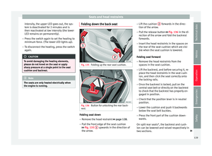 131
131 132
132 133
133 134
134 135
135 136
136 137
137 138
138 139
139 140
140 141
141 142
142 143
143 144
144 145
145 146
146 147
147 148
148 149
149 150
150 151
151 152
152 153
153 154
154 155
155 156
156 157
157 158
158 159
159 160
160 161
161 162
162 163
163 164
164 165
165 166
166 167
167 168
168 169
169 170
170 171
171 172
172 173
173 174
174 175
175 176
176 177
177 178
178 179
179 180
180 181
181 182
182 183
183 184
184 185
185 186
186 187
187 188
188 189
189 190
190 191
191 192
192 193
193 194
194 195
195 196
196 197
197 198
198 199
199 200
200 201
201 202
202 203
203 204
204 205
205 206
206 207
207 208
208 209
209 210
210 211
211 212
212 213
213 214
214 215
215 216
216 217
217 218
218 219
219 220
220 221
221 222
222 223
223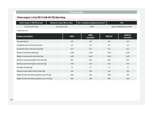 224
224 225
225 226
226 227
227 228
228 229
229 230
230 231
231 232
232 233
233 234
234 235
235 236
236 237
237 238
238 239
239 240
240 241
241 242
242 243
243 244
244 245
245 246
246 247
247