Page 89 of 248

Fuses and bulbs
– Remo
v
e the bulb by pressing on the bulb
holder and turning it anti-clockwise at the
same time.
– Installation involves all of the above steps
in rever
se sequence.
Changing the AFS headlight
bul
bs
Position of the bulbs Fig. 99
AFS headlight bulbs. Turn signal
X
enon he
a
dlight (dipped beam/main
beam)
A B Changing the xenon bulb
The procedure for changing the bulb is the
same on both s
ide
s of the vehicle. WARNING
This type of bulb should be changed at a spe-
ci a
lised workshop. Turn signal bulb
Fig. 100
Turn signal light. –
Raise the bonnet.
– Turn bulb holder ››
›
Fig. 100 A to the left
and p u
l
l.
– Remove the bulb by pressing on the bulb
holder and t
urning it anti-clockwise at the
same time.
– Installation involves all of the above steps
in rever
se sequence. Changing the fog light bulbs
Front f
og light bulb Fig. 101
Front fog light. Fig. 102
Front fog light. –
Remove the bolt ››
›
Fig. 101 1 from the fog
light gri
l
le with a screwdriver.
– Subsequently, remove the clips located on
the edge of the gri
ll with gentle leverage. »
87
Technical data
Advice
Operation
Emergencies
Safety
Page 90 of 248

Emergencies
– Remo
v
e the 3 bolts ››› Fig. 102 2 to re-
mo v
e the f
og light.
– Remove the metal clip situated on the up-
per part
of the fog light by pulling towards
the exterior of the vehicle ››› Fig. 102 3 .
FR version fog-light bulb Fig. 103
Fog light: access to the connector
and t o the light
b
ulb holder. –
Remove the 4 bolts A
› ›
› Fig. 103
from the
inside of the wheel housing and the 2 bot-
tom bolts B
› ›
› Fig. 103
from the bumper
with a screwdriver.
– Pull the bumper to release it from its an-
chorag
es to access the connector and the
light bulb holder. Note
Due to the difficulty of accessing fog light
bu l
bs, have them replaced at a Technical
Service or specialised workshop. Remove the bulb holder
Fig. 104
Front fog light. –
Remove connector ››
›
Fig. 104 1 from the
b u
l
b.
– Turn the bulb holder ›››
Fig. 104 2 to the
l ef
t
and pull.
– Remove the bulb by pressing on the bulb
holder and t
urning it counter-clockwise at
the same time.
– Installation involves all of the above steps
in rever
se sequence.
– Check that the bulb works properly. Changing the tail light bulbs
Summar
y of LED tail lights LED
● Brake lights
● Side lights
Bu l
bs
● Retro fog light
● Reverse lights
● Turn signal
Access to tail lights Fig. 105
Access to tail lights. ●
Open the rear lid.
● Turn the bolt in the direction of the arrow,
b y h
and or with a screwdriver ››› Fig. 105.
88
Page 91 of 248

Fuses and bulbs
● Remo
v
e the tail light, by pulling it out-
wards.
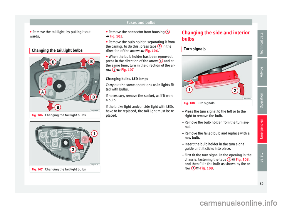
Changing the tail light bulbs Fig. 106
Changing the tail light bulbs Fig. 107
Changing the tail light bulbs ●
Remo
v
e the connector from housing A ›››
Fig. 105.
● Remove the bulb holder, separating it from
the c a
s
ing. To do this, press tabs B in the
dir ection of
the arr
ows ››› Fig. 106.
● When the bulb holder has been removed,
pres
s in the direction of the arrow 1 and at
the s ame time, t
urn in the dir
ection of the ar-
row 2
› ››
Fig. 107
Ch an
ging bulbs. LED lamps
Carry out the same operations as in lights fit-
ted with bulbs.
If necessary, remove the socket, as if it were
a bulb.
If the brake light and/or side light with LEDs
have to be replaced, the tail light must be re-
placed. Changing the side and interior
bul
bs
Turn signals Fig. 108
Turn signals. –
Press the turn signal to the left or to the
right t
o r
emove the bulb.
– Remove the bulb holder from the turn sig-
nal.
– R
emove the failed bulb and replace with a
new bul
b.
– Insert the bulb holder in the turn signal
guide until
it clicks into place.
– First fit the turn signal in the opening in the
cha
ssis, fastening the tabs 1
› ›
› Fig. 108 ,
and then fit in the bulb as shown by the ar-
row 2
› ›
› Fig. 108
.
89
Technical data
Advice
Operation
Emergencies
Safety
Page 92 of 248

Emergencies
Number plate light –
Insert the flat part of a screwdriver into the
spec i
al slot and remove the bulb.
– Remove the bulb holder, by turning it until
it is
free.
– Change the bulb.
– Replace the bulb holder, by turning it until
it fits f
ully.
– Fit the light into the space and press until
you hear a “c
lick”.
Additional brake light* Given the difficulty involved in the replace-
ment
of
thi
s light it should be done by Tech-
nical Services. Interior light and front reading lights Fig. 109
Front reading light. To remove the glass
– Insert a fine screwdriver between the cas-
ing and the gl
a
ss ››› Fig. 109.
– Carefully remove the glass, levering it to
avoid pos
sible damage.
To replace the bulbs
– Pull the bulbs outwards.
– To remove the central bulb, hold and press
to one side.
As
sembly
– Proceed in the reverse order, pressing gen-
tly on the outer edg
e of the side light.
– First fit the glass with the fastening tabs
over the fr
ame of the switch. Next press the front part until the two long tabs click on
the suppor
t.
Luggage compartment light* Fig. 110
Boot light. Fig. 111
Boot light. –
Extract the bulb by pressing on its inside
edg e -arr
ow- using the flat side of a screw-
driver ››› Fig. 110.
90
Page 93 of 248
Fuses and bulbs
– Pr e
s
s the bulb sideways and remove it from
its housing ››› Fig. 111.
91
Technical data
Advice
Operation
Emergencies
Safety
Page 94 of 248
Operation
Fig. 112
Dash panel.92
Page 95 of 248

Controls and displays
Operation
C ontr
o
ls and displays
General instrument panel Door release lever
Light sw
it
ch . . . . . . . . . . . . . . . . . . . . . . 117
Headlight range control* . . . . . . . . . .121
Air vents
Lever f
or:
– Turn signals/main beam head-
lights . . . . . . . . . . . . . . . . . . . . . . . . . . 119
– Crui se c
ontrol* . . . . . . . . . . . . . . . . . 180
Instrument panel and warning
lamp s:
– In
struments . . . . . . . . . . . . . . . . . . . . 94
– Warnin g and indic
ation lamps . . .35
Steering wheel with horn and – Driver airb ag . . . . . . . . . . . . . . . . . . . 66
– On-boar d c
omputer controls . . . .25
– Contro
ls for radio, telephone,
navigation and speech dialogue
system ›››
Booklet Radio
– Paddle levers for tiptronic gear-
shift (automatic gearbox) . . . . . . .161
1 2
3
4
5
6
7 Steering and starter lock
. . . . . . . . . .147
Lever for: – Wind
s
creen wipers and washer . .123
– Window w
asher-wiper system* . .123
– Multi-f
unction display control* . .25
Infotainment system:
Depending on the equipment,
glo
ve compartment with: . . . . . . . . .130
– CD pla
yer* and/or SD card*
››› Booklet Radio
Passenger airbag* . . . . . . . . . . . . . . . . 14
Switches for:
– Heating and
ventilation . . . . . . . . . 139
– Air conditionin g* . . . . . . . . . . . . . . . 141
– C
limatr
onic* . . . . . . . . . . . . . . . . . . . . 143
Depending on the equipment, but-
ton s
for:
– SEAT Drive Profile . . . . . . . . . . . . . . . 182
– Park a
ssist system . . . . . . . . . . . . . . 173
– Hazard w
arning lights . . . . . . . . . .121
– Airbag off w
arning lamp* . . . . . . .68, 70
Depending on the equipment:
– USB/AUX -IN inp
ut . . . . . . . . . . . . . . 105
– Cig ar
ette lighter/Power socket . .132
Drink holder/Ashtray . . . . . . . . . . . . .131
8 9
10
11
12
13
14
15
16 Controls in the centre console:
– St ar
t
-Stop operation button . . . . .170
– Tyr
e pressure monitoring* . . . . . . .213
– Heated r
ear window . . . . . . . . . . . . 123
– Heated se
ats* . . . . . . . . . . . . . . . . . . 128
– Central
locking* . . . . . . . . . . . . . . . . 108
Handbrake lever . . . . . . . . . . . . . . . . . . 149
Gear lever – Automatic* . . . . . . . . . . . . . . . . . . . . . 158
– M
anual . . . . . . . . . . . . . . . . . . . . . . . . . 158
Stor
age space
Pedal
s . . . . . . . . . . . . . . . . . . . . . . . . . . . 61
Steering column control lever* . . . .13
Bonnet release lever . . . . . . . . . . . . . .199
Fuse housing . . . . . . . . . . . . . . . . . . . . . 80
Control for adjusting electric exteri-
or mirrors* . . . . . . . . . . . . . . . . . . . . . . . 126
El
ectric window controls* . . . . . . . . .114 Note
Some of the items of equipment listed here
are fitt ed on
ly on certain model versions or
are optional extras. 17
18
19
20
21
22
23
24
25
26
93
Technical data
Advice
Operation
Emergencies
Safety
Page 96 of 248
Operation
Instruments and warning/control lamps
In s
trument
s
General instrument panel Fig. 113
Instrument panel, on dash panel The layout of the instruments depends upon
the model
and the en
gine.
R
ev counter (with the engine running, in
hundreds of revolutions per minute)
››› page 95.
The beginning of the red zone of the rev
counter indicates the maximum speed in
any gear after running-in and with the en-
gine hot. However, it is advisable to
1 change up a gear or move the selector
l
ev
er t
o D (or lift your foot off the acceler-
ator) before the needle reaches the red
zone ››› .
En gine c
oo
lant temperature display
››› page 97.
Displays on the screen ››› page 95.
Adjuster button and display
››› page 97.
2 3
4 Speedometer.
F
uel
g
auge ››› page 98. WARNING
Any distraction may lead to an accident, with
the risk of
injury.
● Do not operate the instrument panel con-
trol
s when driving. 5
6
94