2016 NISSAN NOTE warning
[x] Cancel search: warningPage 611 of 3641

CHG-16
< BASIC INSPECTION >
DIAGNOSIS AND REPAIR WORKFLOW
>> GO TO 2.
2.STOP POWER GENERATION VOLTAGE VARIABLE CONTROL SYSTEM
Stop the operation of the power generation voltage variabl e control in either of the following procedures.
• After selecting “ENGINE” using CONSULT, set the DUTY value of “ALTERNATOR DUTY” to 0 % by select-
ing “ALTERNATOR DUTY” of “Active Test”. Continue “Active Test” until the end of inspection. (When the
DUTY value is 0 or 100 %, the normal power generation is performed according to the characteristic of the
IC regulator of the generator.)
• Turn the ignition switch OFF, and disconnect the batte ry current sensor connector. [However, DTC (P1550–
P1554) of the engine might remain. After finishing the inspection, connect the battery current sensor connec-
tor and erase the self diagnosis results history of the engine using CONSULT.]
>> GO TO 3.
3.DIAGNOSIS WITH EXP-800 NI OR GR8-1200 NI
Perform the charging system test using Multitasking battery and electrical diagnostic station GR8-1200 NI or
Battery and electrical diagnostic analyzer EXP-800 NI. Refer to the applicable Instruction Manual for proper
testing procedures.
Te s t r e s u l t
NO PROBLEMS>>Charging system is normal and will also show “DIODE RIPPLE” test result.
NO VOLTAGE>>GO TO 4.
LOW VOLTAGE>>GO TO 12.
HIGH VOLTAGE>>GO TO 14.
EXCESSIVE RIPPLE, OPEN PHASE, OPEN DIODE or SHORTED DIODE>>Replace the generator. Refer
to CHG-29, "
Removal and Installation". Perform “DIODE RIPPLE” test again using Multitasking
battery and electrical diagnostic station GR8-1200 NI or Battery and electrical diagnostic analyzer
EXP-800 NI to confirm repair.
4.INSPECTION WITH CHARGE WARNING LAMP (IGNITION SWITCH IS ON)
Turn the ignition switch ON.
Does the charge warning lamp illuminate?
YES >> GO TO 6.
NO >> GO TO 5.
5.“L” TERMINAL CIRCUIT (OPEN) INSPECTION
Check “L” terminal circuit (open). Refer to CHG-24, "
Diagnosis Procedure".
Is the
“L” terminal circuit normal?
YES >> Replace generator. Refer to CHG-29, "Removal and Installation".
NO >> Repair as needed.
6.INSPECTION WITH CHARGE WARNING LAMP (IDLING)
Start the engine and run it at idle.
Does the charge warning lamp turn OFF?
YES >> GO TO 9.
NO >> GO TO 7.
7.“L” TERMINAL CIRCUIT (SHORT) INSPECTION
Check “L” terminal circuit (short). Refer to CHG-26, "
Diagnosis Procedure".
Is the
“L” terminal circuit normal?
YES >> GO TO 8.
NO >> Repair as needed.
8.“S” TERMINAL CIRCUIT INSPECTION
Check “S” terminal circuit. Refer to CHG-27, "
Diagnosis Procedure".
Is the
“S” terminal circuit normal?
YES >> GO TO 10.
Revision: August 2015 2016 Versa Note
cardiagn.com
Page 612 of 3641
CHG
DIAGNOSIS AND REPAIR WORKFLOWCHG-17
< BASIC INSPECTION >
C
DE
F
G H
I
J
K L
B A
O P
N
NO >> Repair as needed.
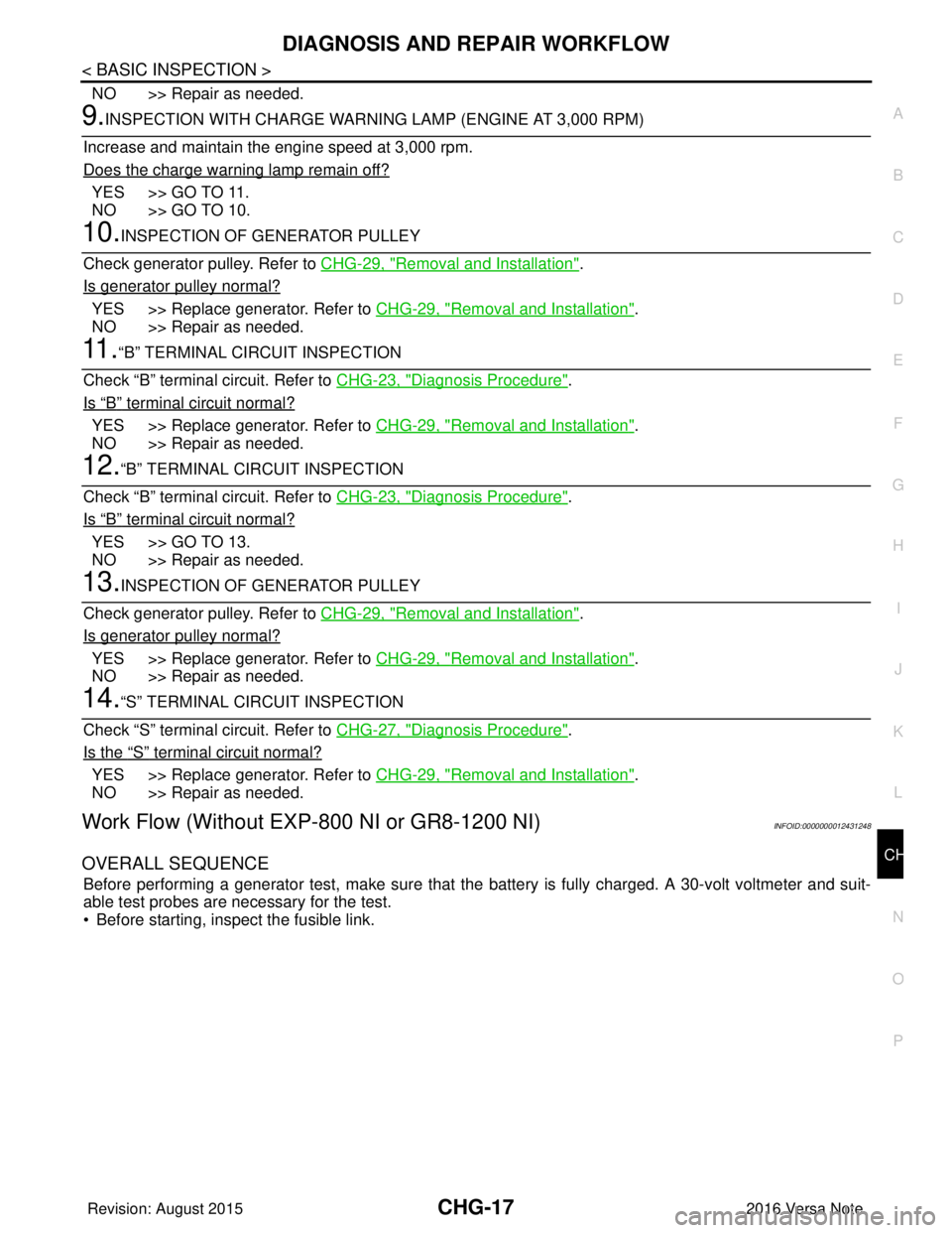
9.INSPECTION WITH CHARGE WARNING LAMP (ENGINE AT 3,000 RPM)
Increase and maintain the engine speed at 3,000 rpm.
Does the charge warning lamp remain off?
YES >> GO TO 11.
NO >> GO TO 10.
10.INSPECTION OF GENERATOR PULLEY
Check generator pulley. Refer to CHG-29, "
Removal and Installation".
Is generator pulley normal?
YES >> Replace generator. Refer to CHG-29, "Removal and Installation".
NO >> Repair as needed.
11 .“B” TERMINAL CIRCUIT INSPECTION
Check “B” terminal circuit. Refer to CHG-23, "
Diagnosis Procedure".
Is
“B” terminal circuit normal?
YES >> Replace generator. Refer to CHG-29, "Removal and Installation".
NO >> Repair as needed.
12.“B” TERMINAL CIRCUIT INSPECTION
Check “B” terminal circuit. Refer to CHG-23, "
Diagnosis Procedure".
Is
“B” terminal circuit normal?
YES >> GO TO 13.
NO >> Repair as needed.
13.INSPECTION OF GENERATOR PULLEY
Check generator pulley. Refer to CHG-29, "
Removal and Installation".
Is generator pulley normal?
YES >> Replace generator. Refer to CHG-29, "Removal and Installation".
NO >> Repair as needed.
14.“S” TERMINAL CIRCUIT INSPECTION
Check “S” terminal circuit. Refer to CHG-27, "
Diagnosis Procedure".
Is the
“S” terminal circuit normal?
YES >> Replace generator. Refer to CHG-29, "Removal and Installation".
NO >> Repair as needed.
Work Flow (Without EXP-800 NI or GR8-1200 NI)INFOID:0000000012431248
OVERALL SEQUENCE
Before performing a generator test, make sure that the battery is fully charged. A 30-volt voltmeter and suit-
able test probes are necessary for the test.
• Before starting, inspect the fusible link.
Revision: August 2015 2016 Versa Note
cardiagn.com
Page 613 of 3641

CHG-18
< BASIC INSPECTION >
DIAGNOSIS AND REPAIR WORKFLOW
• Use fully charged battery.
DETAILED FLOW
1.PRELIMINARY INSPECTION
Perform the preliminary inspection. Refer to CHG-20, "
Diagnosis Procedure".
>> GO TO 2.
2.STOP POWER GENERATION VOLT AGE VARIABLE CONTROL SYSTEM
Stop the operation of the power generation voltage variabl e control in either of the following procedures:
• After selecting “ENGINE” using CONSULT, set the DUTY value of “ALTERNATOR DUTY” to 0 % by select-
ing “ALTERNATOR DUTY” with “Active Test”. Continue “Active Test” until the end of inspection. (When the
DUTY value is 0 or 100 %, the normal power generation is performed according to the characteristic of the
IC regulator of the generator.)
• Turn the ignition switch OFF, and disconnect the batte ry current sensor connector. [However, DTC (P1550 -
P1554) of the engine might remain. After finishing the inspection, connect the battery current sensor connec-
tor and erase the self-diagnostic results history of the engine using CONSULT.]
>> GO TO 3.
3.INSPECTION WITH CHARGE WARNING LAMP (IGNITION SWITCH IS TURNED ON)
When ignition switch is turned ON.
Does the charge warning lamp illuminate?
YES >> GO TO 4.
NO >> GO TO 10.
4.INSPECTION WITH CHARGE WARNING LAMP (IDLING)
Start the engine and run it at idle
Does the charge warning lamp turn OFF?
ALMIA0577GB
Revision: August 2015 2016 Versa Note
cardiagn.com
Page 614 of 3641
CHG
DIAGNOSIS AND REPAIR WORKFLOWCHG-19
< BASIC INSPECTION >
C
DE
F
G H
I
J
K L
B A
O P
N
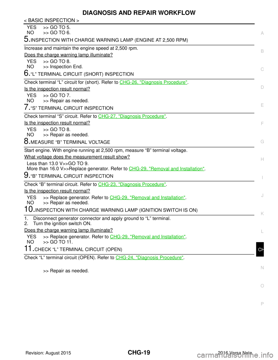
YES >> GO TO 5.
NO >> GO TO 6.
5.INSPECTION WITH CHARGE WARNING LAMP (ENGINE AT 2,500 RPM)
Increase and maintain the engine speed at 2,500 rpm.
Does the charge warning lamp illuminate?
YES >> GO TO 8.
NO >> Inspection End.
6.“L” TERMINAL CIRCUIT (SHORT) INSPECTION
Check terminal “L” circuit for (short). Refer to CHG-26, "
Diagnosis Procedure".
Is the inspection result normal?
YES >> GO TO 7.
NO >> Repair as needed.
7.“S” TERMINAL CIRCUIT INSPECTION
Check terminal “S” circuit. Refer to CHG-27, "
Diagnosis Procedure".
Is the inspection result normal?
YES >> GO TO 8.
NO >> Repair as needed.
8.MEASURE “B” TERMINAL VOLTAGE
Start engine. With engine running at 2,500 rpm, measure “B” terminal voltage.
What voltage does the measurement result show?
Less than 13.0 V>>GO TO 9.
More than 16.0 V>>Replace generator. Refer to CHG-29, "
Removal and Installation".
9.“B” TERMINAL CIRCUIT INSPECTION
Check “B” terminal circuit. Refer to CHG-23, "
Diagnosis Procedure".
Is the inspection result normal?
YES >> Replace generator. Refer to CHG-29, "Removal and Installation".
NO >> Repair as needed.
10.INSPECTION WITH CHARGE WARNING LAMP (IGNITION SWITCH IS ON)
1. Disconnect generator connector and apply ground to “L” terminal.
2. Turn the ignition switch ON.
Does the charge warning lamp illuminate?
YES >> Replace generator. Refer to CHG-29, "Removal and Installation".
NO >> GO TO 11.
11 .CHECK “L” TERMINAL CIRCUIT (OPEN)
Check “L” terminal circuit (OPEN). Refer to CHG-24, "
Diagnosis Procedure".
>> Repair as needed.
Revision: August 2015 2016 Versa Note
cardiagn.com
Page 619 of 3641
CHG-24
< DTC/CIRCUIT DIAGNOSIS >
L TERMINAL CIRCUIT (OPEN)
L TERMINAL CIRCUIT (OPEN)
DescriptionINFOID:0000000012431253
The “L” terminal circuit controls the charge warning lamp. The charge warning lamp turns ON when the igni-
tion switch is set to ON or START. When the generator is providing sufficient voltage with the engine running,
the charge warning lamp turns OFF. If the charge warn ing lamp illuminates with the engine running, a malfunc-
tion is indicated.
Diagnosis ProcedureINFOID:0000000012431254
Regarding Wiring Diagram information. Refer to CHG-9, "Wiring Diagram".
1.CHECK “L” TERMINAL CONNECTION
1. Turn ignition switch OFF.
2. Check if “L” terminal is clean and tight.
Is the inspection result normal?
YES >> GO TO 2.
NO >> Repair “L” terminal connection. Confirm repa ir by performing complete Charging system test
using EXP-800 NI or GR8-1200 NI (if available). Refer to applicable Instruction Manual for proper
testing procedures.
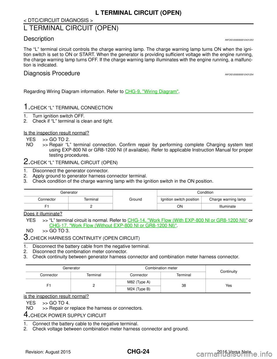
2.CHECK “L” TERMIN AL CIRCUIT (OPEN)
1. Disconnect the generator connector.
2. Apply ground to generator harness connector terminal.
3. Check condition of the charge warning lamp with the ignition switch in the ON position.
Does it illuminate?
YES >> “L” terminal circuit is normal. Refer to CHG-14, "Work Flow (With EXP-800 NI or GR8-1200 NI)" or
CHG-17, "
Work Flow (Without EXP-800 NI or GR8-1200 NI)".
NO >> GO TO 3.
3.CHECK HARNESS CONTI NUITY (OPEN CIRCUIT)
1. Disconnect the battery cable from the negative terminal.
2. Disconnect the combination meter connector.
3. Check continuity between generator harness c onnector and combination meter harness connector.
is the inspection result normal?
YES >> GO TO 4.
NO >> Repair or replace the harness or connectors.
4.CHECK POWER SUPPLY CIRCUIT
1. Connect the battery cable to the negative terminal.
2. Check voltage between combination meter harness connector and ground.
Generator
GroundCondition
Connector Terminal Ignition switch position Charge warning lamp
F1 2 ONIlluminate
Generator Combination meter
Continuity
Connector TerminalConnector Terminal
F1 2M82 (Type A)
38Yes
M24 (Type B)
Revision: August 2015 2016 Versa Note
cardiagn.com
Page 621 of 3641
CHG-26
< DTC/CIRCUIT DIAGNOSIS >
L TERMINAL CIRCUIT (SHORT)
L TERMINAL CIRCUIT (SHORT)
DescriptionINFOID:0000000012431255
The terminal “L” circuit controls the charge warning lamp. The charge warning lamp turns ON when the igni-
tion switch is set to ON or START. When the generator is providing sufficient voltage with the engine running,
the charge warning lamp turns off. If the charge warning lamp illuminates with the engine running, a malfunc-
tion is indicated.
Diagnosis ProcedureINFOID:0000000012431256
Regarding Wiring Diagram information, refer to CHG-9, "Wiring Diagram".
1.CHECK “L” TERMINAL CIRCUIT (SHORT)
1. Turn ignition switch OFF.
2. Disconnect generator connector.
3. Turn ignition switch ON.
Does charge warning lamp illuminate?
YES >> GO TO 2.
NO >> Refer to CHG-14, "
Work Flow (With EXP-800 NI or GR8-1200 NI)" or CHG-17, "Work Flow (With-
out EXP-800 NI or GR8-1200 NI)".
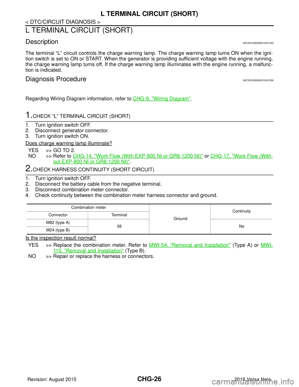
2.CHECK HARNESS CONTI NUITY (SHORT CIRCUIT)
1. Turn ignition switch OFF.
2. Disconnect the battery cable from the negative terminal.
3. Disconnect combination meter connector.
4. Check continuity between the combination meter harness connector and ground.
Is the inspection result normal?
YES >> Replace the combination meter. Refer to MWI-54, "Removal and Installation" (Type A) or MWI-
115, "Removal and Installation" (Type B).
NO >> Repair or replace the harness or connectors.
Combination meter
GroundContinuity
Connector Terminal
M82 (type A) 38 No
M24 (type B)
Revision: August 2015 2016 Versa Note
cardiagn.com
Page 623 of 3641
CHG-28
< SYMPTOM DIAGNOSIS >
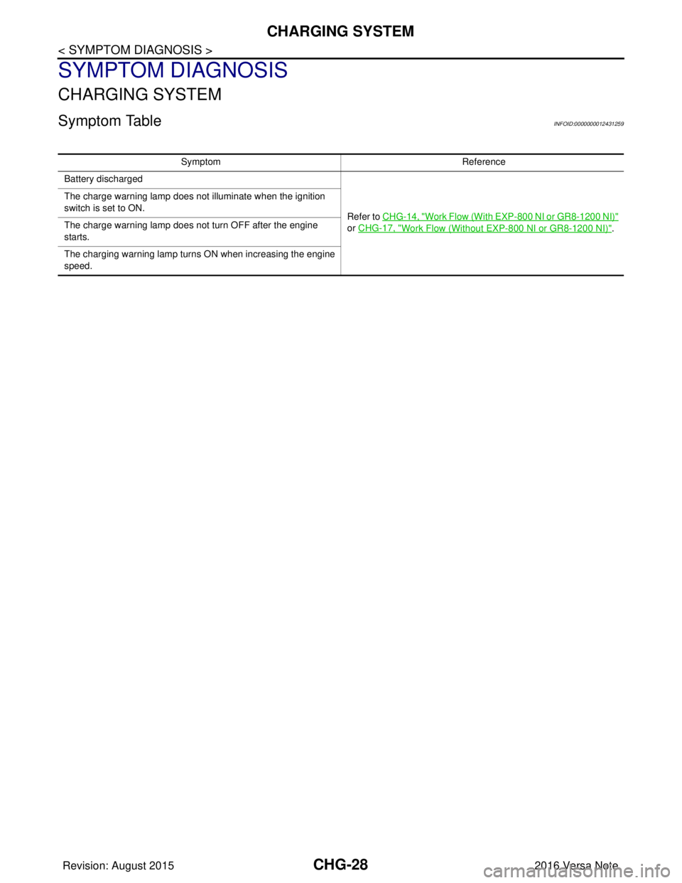
CHARGING SYSTEM
SYMPTOM DIAGNOSIS
CHARGING SYSTEM
Symptom TableINFOID:0000000012431259
SymptomReference
Battery discharged
Refer to CHG-14, "
Work Flow (With EXP-800 NI or GR8-1200 NI)"
or CHG-17, "
Work Flow (Without EXP-800 NI or GR8-1200 NI)".
The charge warning lamp does not illuminate when the ignition
switch is set to ON.
The charge warning lamp does not turn OFF after the engine
starts.
The charging warning lamp turns ON when increasing the engine
speed.
Revision: August 2015
2016 Versa Note
cardiagn.com
Page 628 of 3641

CL-2
< PRECAUTION >
PRECAUTIONS
PRECAUTION
PRECAUTIONS
Precaution for Supplemental Restraint System (SRS) "AIR BAG" and "SEAT BELT
PRE-TENSIONER"
INFOID:0000000012432210
The Supplemental Restraint System such as “A IR BAG” and “SEAT BELT PRE-TENSIONER”, used along
with a front seat belt, helps to reduce the risk or severity of injury to the driver and front passenger for certain
types of collision. Information necessary to service the system safely is included in the SR and SB section of
this Service Manual.
WARNING:
• To avoid rendering the SRS inopera tive, which could increase the risk of personal injury or death in
the event of a collision which would result in air bag inflation, all maintenance must be performed by
an authorized NISSAN/INFINITI dealer.
• Improper maintenance, including in correct removal and installation of the SRS, can lead to personal
injury caused by unintent ional activation of the system. For re moval of Spiral Cable and Air Bag
Module, see the SR section.
• Do not use electrical test equipmen t on any circuit related to the SRS unless instructed to in this
Service Manual. SRS wiring harn esses can be identified by yellow and/or orange harnesses or har-
ness connectors.
PRECAUTIONS WHEN USING POWER TOOLS (AIR OR ELECTRIC) AND HAMMERS
WARNING:
• When working near the Airbag Diagnosis Sensor Unit or other Airbag System sensors with the Igni-
tion ON or engine running, DO NOT use air or electri c power tools or strike near the sensor(s) with a
hammer. Heavy vibration could activate the sensor( s) and deploy the air bag(s), possibly causing
serious injury.
• When using air or electric power tools or hammers , always switch the Ignition OFF, disconnect the
battery and wait at least three minutes before performing any service.
General PrecautionsINFOID:0000000012432211
WARNING:
After cleaning clutch disc, wipe it with a dust collector. Do not use compressed air.
CAUTION:
• Always use recommended clutch fluid. Refer to MA-11, "
Fluids and Lubricants".
• Do not reuse drained clutch fluid.
• Keep painted surface on the body and other parts free of clutch fluid. If fluid spills, wipe up immedi-
ately and wash the affected area with water.
• Do not use mineral oils, such as gasoline or kerosen e. It will ruin the rubber parts of the hydraulic
system.
• Do not reuse CSC (Concentric Slave Cylinder). CS C slides back to the original position every time
when removing transaxle assembly. At this time, dust on the sliding parts may damage the seal of
CSC and may cause clutch fluid leakage. Refer to CL-17, "
Removal and Installation".
• Do not disassemble clutch master cylinder and CSC.
Revision: August 2015 2016 Versa Note
cardiagn.com