2016 NISSAN NOTE coolant temperature
[x] Cancel search: coolant temperaturePage 2218 of 3641
![NISSAN NOTE 2016 Service Repair Manual LAN-30
< SYSTEM DESCRIPTION >[CAN]
SYSTEM
CAN COMMUNICATION SYSTEM : CA N Communication Signal Chart
INFOID:0000000012433349
Refer to LAN-15, "How to Use CAN Communication Signal Chart" for how to use NISSAN NOTE 2016 Service Repair Manual LAN-30
< SYSTEM DESCRIPTION >[CAN]
SYSTEM
CAN COMMUNICATION SYSTEM : CA N Communication Signal Chart
INFOID:0000000012433349
Refer to LAN-15, "How to Use CAN Communication Signal Chart" for how to use](/manual-img/5/57363/w960_57363-2217.png)
LAN-30
< SYSTEM DESCRIPTION >[CAN]
SYSTEM
CAN COMMUNICATION SYSTEM : CA N Communication Signal Chart
INFOID:0000000012433349
Refer to LAN-15, "How to Use CAN Communication Signal Chart" for how to use CAN communication signal
chart.
NOTE:
• Refer to LAN-21, "
Abbreviation List" for the abbreviations of the connecting units.
• The air bag diagnosis sensor unit and AV control unit uses CAN communication only for communicating with
the diagnostic tool (not with other connected control units).
T: Transmit R: Receive
NAVI switches Side camera LH
With navigation system With around view monitor system
ALMIA0821ZZ
Signal nameECM
ABS
IPDM-E TCM
AV M EPS
M&A
STRG BCM
Accelerator pedal position signal T RR
A/C compressor request signal TR
Closed throttle position signal TR
Cooling fan speed request signal TR
ECO pedal guide signal TR
Engine and CVT integrated control signal TR
RT
Engine coolant temperature signal TR R R
Engine speed signal T RR R
Engine status signal T RR R
Fuel filler cap warning display signal TR
N idle instruction signal TR
RT
Malfunctioning indicator lamp signal TR
RT
Oil pressure warning lamp signal TR
Power generation command value signal TR
ABS warning lamp signal TR
VDC warning lamp signal TR
VDC OFF indicator lamp signal TR
Revision: August 2015 2016 Versa Note
cardiagn.com
Page 2321 of 3641

MA-6
< PERIODIC MAINTENANCE >
GENERAL MAINTENANCE
UNDER THE HOOD AND VEHICLE
The maintenance items listed here should be checked periodically (e.g. each time you check the engine oil or refuel).
SeatsCheck seat position controls such as seat adjusters, seatback recliner, etc. to
make sure they operate smoothly and that all latches lock securely in every po-
sition. Check that the head restraints move up and down smoothly and that the
locks (if equipped) hold securely in all latched positions. Check that the latches
lock securely for folding-down rear seatbacks. —
Seat belts Check that all parts of the seat belt system (e.g. buckles, anchors, adjusters and
retractors) operate properly and smoothly and are installed securely. Check the
belt webbing for cuts, fraying, wear or damage. MA-43
Accelerator pedal
Check the pedal for smooth operation and make sure the pedal does not catch
or require uneven effort. Keep the floor mats away from the pedal. —
Brakes Check that the brake does not pull the vehicle to one side when applied. —
Brake pedal and
booster Check the pedal for smooth operation and make sure it has the proper distance
under it when depressed fully. Check the brake booster function. Be sure to keep
floor mats away from the pedal. BR-9
Clutch pedal
Make sure the pedal operates smoothly and check that it has the proper free play. CL-5
Parking brakeCheck that the lever or pedal has the proper travel and make sure that the vehicle
is held securely on a fairly steep hill when only the parking brake is applied. PB-4
CVT "P" (Park) posi-
tion mechanismOn a fairly steep hill check that the vehicle is held securely with the shift selector
in the "P" (PARK) position without applying any brakes.
—
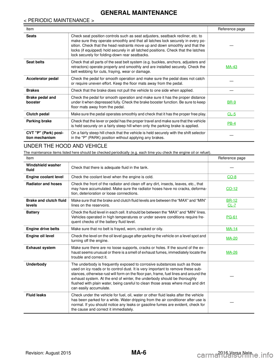
Item
Reference page
Item Reference page
Windshield washer
fluid Check that there is adequate fluid in the tank.
—
Engine coolant level Check the coolant level when the engine is cold. CO-8
Radiator and hosesCheck the front of the radiator and clean off any dirt, insects, leaves, etc., that
may have accumulated. Make sure the radiator hoses have no cracks, deforma-
tion, deterioration or loose connections. CO-12
Brake and clutch fluid
levelsMake sure that the brake and clutch fluid levels are between the “MAX” and “MIN”
lines on the reservoirs. BR-12
CL-7
Battery
Check the fluid level in each cell. It should be between the “MAX” and “MIN” lines.
Vehicles operated in high temperatures or under severe conditions require fre-
quent checks of the battery fluid level. PG-61
Engine drive belts
Make sure that no belt is frayed, worn, cracked or oily. MA-14
Engine oil levelCheck the level on the oil level gauge after parking the vehicle on a level spot and
turning off the engine. MA-20
Exhaust system
Make sure there are no loose supports, cracks or holes. If the sound of the ex-
haust seems unusual or there is a smell of exhaust fumes, immediately locate the
trouble and correct it. MA-26
Underbody
The underbody is frequently exposed to corrosive substances such as those
used on icy roads or to control dust. It is very important to remove these sub-
stances, otherwise rust will form on the floor pan, frame, fuel lines and around the
exhaust system. At the end of winter, the underbody should be thoroughly
flushed with plain water, being careful to clean those areas where mud and dirt
can easily accumulate. —
Fluid leaks Check under the vehicle for fuel, oil, water or other fluid leaks after the vehicle
has been parked for a while. Water dripping from the air conditioner after use is
normal. If you should notice any leaks or gasoline fumes are evident, check for
the cause and correct it immediately. —
Revision: August 2015
2016 Versa Note
cardiagn.com
Page 2333 of 3641

MA-18
< PERIODIC MAINTENANCE >
ENGINE MAINTENANCE
ENGINE COOLANT : Flushing Cooling System
INFOID:0000000012432255
1. Install radiator drain plug and reservoir tank, if removed.
CAUTION:
Be sure to clean drain plug and install with new O-ring.
2. If water drain plugs on cylinder block were removed, close and tighten them. Refer to EM-93, "
Exploded
View".
3. Remove air duct from between air cleaner case and electric throttle control actuator. Refer to EM-26,
"Removal and Installation".
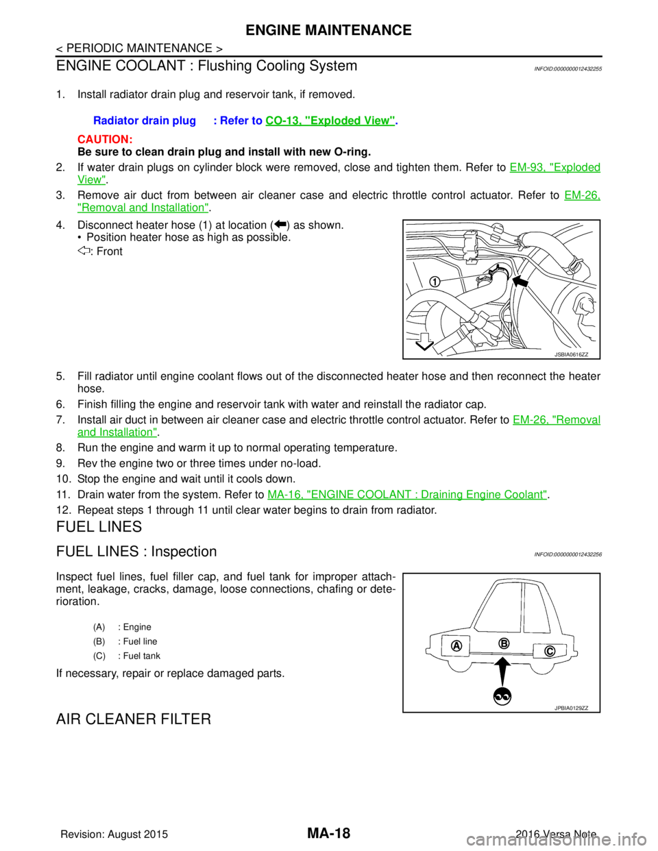
4. Disconnect heater hose (1) at location ( ) as shown. • Position heater hose as high as possible.
: Front
5. Fill radiator until engine coolant flows out of the disconnected heater hose and then reconnect the heater
hose.
6. Finish filling the engine and reservoir tank with water and reinstall the radiator cap.
7. Install air duct in between air cleaner case and electric throttle control actuator. Refer to EM-26, "
Removal
and Installation".
8. Run the engine and warm it up to normal operating temperature.
9. Rev the engine two or three times under no-load.
10. Stop the engine and wait until it cools down.
11. Drain water from the system. Refer to MA-16, "
ENGINE COOLANT : Draining Engine Coolant".
12. Repeat steps 1 through 11 until clear water begins to drain from radiator.
FUEL LINES
FUEL LINES : InspectionINFOID:0000000012432256
Inspect fuel lines, fuel filler cap, and fuel tank for improper attach-
ment, leakage, cracks, damage, l oose connections, chafing or dete-
rioration.
If necessary, repair or replace damaged parts.
AIR CLEANER FILTER
Radiator drain plug : Refer to CO-13, "Exploded View".
JSBIA0616ZZ
(A) : Engine
(B) : Fuel line
(C) : Fuel tank
JPBIA0129ZZ
Revision: August 2015 2016 Versa Note
cardiagn.com
Page 2335 of 3641

MA-20
< PERIODIC MAINTENANCE >
ENGINE MAINTENANCE
2. Remove the air cleaner filter (1) from the air cleaner body.
INSTALLATION
Installation is in the reverse order of removal.
NOTE:
Check that the air cleaner filter is securely placed in the air cleaner body.
ENGINE OIL
ENGINE OIL : InspectionINFOID:0000000012432259
ENGINE OIL LEVEL
NOTE:
Before starting engine, position the vehicle so that it is level and check the engine oil level. If engine is already
started, stop it and allow 10 minutes before checking.
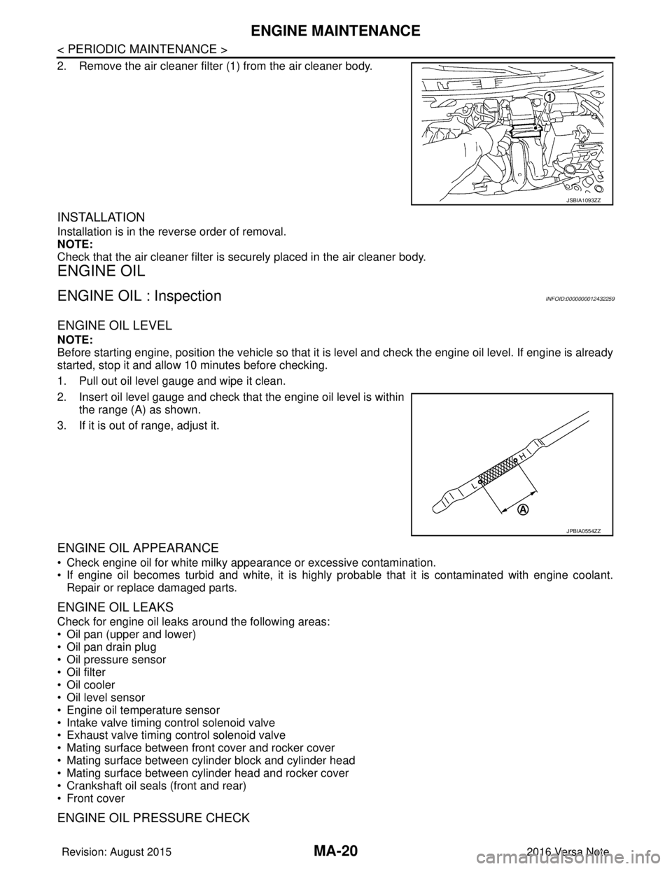
1. Pull out oil level gauge and wipe it clean.
2. Insert oil level gauge and check that the engine oil level is withinthe range (A) as shown.
3. If it is out of range, adjust it.
ENGINE OIL APPEARANCE
• Check engine oil for white milky appearance or excessive contamination.
• If engine oil becomes turbid and white, it is highl y probable that it is contaminated with engine coolant.
Repair or replace damaged parts.
ENGINE OIL LEAKS
Check for engine oil leaks around the following areas:
• Oil pan (upper and lower)
• Oil pan drain plug
• Oil pressure sensor
• Oil filter
• Oil cooler
• Oil level sensor
• Engine oil temperature sensor
• Intake valve timing control solenoid valve
• Exhaust valve timing control solenoid valve
• Mating surface between front cover and rocker cover
• Mating surface between cylinder block and cylinder head
• Mating surface between cylinder head and rocker cover
• Crankshaft oil seals (front and rear)
• Front cover
ENGINE OIL PRESSURE CHECK
JSBIA1093ZZ
JPBIA0554ZZ
Revision: August 2015 2016 Versa Note
cardiagn.com
Page 2367 of 3641
![NISSAN NOTE 2016 Service Repair Manual MWI
COMPONENT PARTSMWI-9
< SYSTEM DESCRIPTION > [TYPE A]
C
D
E
F
G H
I
J
K L
M B A
O P
METER SYSTEM : Combination MeterINFOID:0000000012432542
The combination meter controls the following items a ccor NISSAN NOTE 2016 Service Repair Manual MWI
COMPONENT PARTSMWI-9
< SYSTEM DESCRIPTION > [TYPE A]
C
D
E
F
G H
I
J
K L
M B A
O P
METER SYSTEM : Combination MeterINFOID:0000000012432542
The combination meter controls the following items a ccor](/manual-img/5/57363/w960_57363-2366.png)
MWI
COMPONENT PARTSMWI-9
< SYSTEM DESCRIPTION > [TYPE A]
C
D
E
F
G H
I
J
K L
M B A
O P
METER SYSTEM : Combination MeterINFOID:0000000012432542
The combination meter controls the following items a ccording to the signals received from each unit via CAN
communication and the signals from switches and sensors:
• Measuring instruments
• Indicator lamps
• Warning lamps
• Meter illumination control
• Information display
ARRANGEMENT OF COMBINATION METER
6. ECM Transmits the following signals to the combination meter via CAN communication:
• Engine speed signal
• Engine coolant temperature signal
• Fuel consumption monitor signal
• Engine oil pressure sensor signal
Refer to EC-14, "
ENGINE CONTROL SYSTEM : ComponentPartsLocation" for de-
tailed installation location.
7. BCM Transmits the following signals to the combination meter via CAN communication:
• Door switch signal
• Buzzer signal
Refer to BCS-137, "
Removal and Installation" for detailed installation location.
8. Combination meter Refer to MWI-9, "
METER SYSTEM : Combination Meter".
9. Fuel level sensor unit and fuel pump
(fuel level sensor) Transmits the fuel level sensor signal to the combination meter.
No.
Component Function
U: USAEU: Except USA
AWNIA3633ZZ
Revision: August 2015 2016 Versa Note
cardiagn.com
Page 2368 of 3641
![NISSAN NOTE 2016 Service Repair Manual MWI-10
< SYSTEM DESCRIPTION >[TYPE A]
SYSTEM
SYSTEM
METER SYSTEM
METER SYSTEM : System DescriptionINFOID:0000000012432543
SYSTEM DIAGRAM
COMBINATION METER INPUT SIGNAL (CAN COMMUNICATION SIGNAL)
DESCR NISSAN NOTE 2016 Service Repair Manual MWI-10
< SYSTEM DESCRIPTION >[TYPE A]
SYSTEM
SYSTEM
METER SYSTEM
METER SYSTEM : System DescriptionINFOID:0000000012432543
SYSTEM DIAGRAM
COMBINATION METER INPUT SIGNAL (CAN COMMUNICATION SIGNAL)
DESCR](/manual-img/5/57363/w960_57363-2367.png)
MWI-10
< SYSTEM DESCRIPTION >[TYPE A]
SYSTEM
SYSTEM
METER SYSTEM
METER SYSTEM : System DescriptionINFOID:0000000012432543
SYSTEM DIAGRAM
COMBINATION METER INPUT SIGNAL (CAN COMMUNICATION SIGNAL)
DESCRIPTION
Combination Meter
• The combination meter receives necessary signals from each unit, switch, and sensor to control the follow-
ing functions.
- Measuring instruments
- Warning lamps
- Indicator lamps
- Meter illumination control
- Information display
• The combination meter incorporates a buzzer function that sounds an audible alarm with the integrated buzzer device. Refer to WCS-7, "
WARNING CHIME SYSTEM : System Description" for further details.
AWNIA3080GB
Transmit unit Signal name
ABS actuator and electric unit (c ontrol unit) Vehicle speed signal
BCM Door switch signal
Buzzer signal
TCM Shift position signal
ECM Engine speed signal
Engine coolant temperature signal
Engine oil pressure signal
Fuel consumption signal
Loose fuel cap signal
Revision: August 2015
2016 Versa Note
cardiagn.com
Page 2369 of 3641
![NISSAN NOTE 2016 Service Repair Manual MWI
SYSTEMMWI-11
< SYSTEM DESCRIPTION > [TYPE A]
C
D
E
F
G H
I
J
K L
M B A
O P
• The combination meter includes an on board diagnosis function.
• The combination meter can be diagnosed with CONSUL NISSAN NOTE 2016 Service Repair Manual MWI
SYSTEMMWI-11
< SYSTEM DESCRIPTION > [TYPE A]
C
D
E
F
G H
I
J
K L
M B A
O P
• The combination meter includes an on board diagnosis function.
• The combination meter can be diagnosed with CONSUL](/manual-img/5/57363/w960_57363-2368.png)
MWI
SYSTEMMWI-11
< SYSTEM DESCRIPTION > [TYPE A]
C
D
E
F
G H
I
J
K L
M B A
O P
• The combination meter includes an on board diagnosis function.
• The combination meter can be diagnosed with CONSULT.
METER CONTROL FUNCTION LIST
METER SYSTEM : Fail-safeINFOID:0000000012432544
The combination meter activates the fail-safe contro l if CAN communication with each unit is malfunctioning.
System DescriptionReference
Measuring instruments Speedometer
Indicates vehicle speed. MWI-12,
"SPEEDOME-
TER : System De-
scription"
Tachometer
Indicates engine speed. MWI-12, "
TA -
CHOMETER :
System Descrip-
tion"
Shift position indicator
Indicates shift position.MWI-13, "
SHIFT
POSITION INDI-
CATOR : System
Description"
Warning lamp/indicator
lamp
Engine oil pressure warning lamp The warning lamp turns ON or turns OFF,
according to engine hydraulic pressure. MWI-13, "
OIL
PRESSURE
WARNING LAMP
: System Descrip-
tion"
Meter illumination con-
trol
Meter illumination control function
Controls the back light of combination meter. MWI-13, "
METER
ILLUMINATION
CONTROL : Sys-
tem Description"
Information displayOdo/trip meter Indicates mileage.
MWI-14, "
INFOR-
MATION DIS-
PLAY : System
Description"
Engine coolant temperature gauge Indicates engine coolant temperature.
Fuel gaugeIndicates fuel level.
Loose fuel cap warning Indicates loose fuel cap.
Low fuel warning Indicates fuel level.
Trip computer Instant fuel consumption Displays current fuel consumption.
Average fuel consumption Displays average fuel consumption.
Distance to empty Displays distance to empty.
Travel distance
Displays mileage.
Function Specifications
Speedometer Reset to zero by suspending communication.
Tachometer
Illumination control When suspending communication, changes to nighttime mode.
Shift position indicator When suspending communication, not indicate.
Information display Trip com-
puterCurrent fuel consump-
tion
• When reception time of an abnormal signal is 2 seconds or
less, the last received datum is used for calculation to indi-
cate the result.
• When reception time of an abnormal signal is more than two
seconds, the last result calculated during normal condition is
indicated.
Average fuel consump-
tion
Distance to empty
Engine coolant temperature gauge Reset to zero by suspending communication.
Odo/trip meter An indicated value is maintained at communications blackout.
Buzzer The buzzer turns OFF by suspending communication.
Revision: August 2015 2016 Versa Note
cardiagn.com
Page 2372 of 3641
![NISSAN NOTE 2016 Service Repair Manual MWI-14
< SYSTEM DESCRIPTION >[TYPE A]
SYSTEM
• The combination meter turns OFF meter illumination when the following conditions are satisfied.
INFORMATION DISPLAY
INFORMATION DISPLAY : System Descri NISSAN NOTE 2016 Service Repair Manual MWI-14
< SYSTEM DESCRIPTION >[TYPE A]
SYSTEM
• The combination meter turns OFF meter illumination when the following conditions are satisfied.
INFORMATION DISPLAY
INFORMATION DISPLAY : System Descri](/manual-img/5/57363/w960_57363-2371.png)
MWI-14
< SYSTEM DESCRIPTION >[TYPE A]
SYSTEM
• The combination meter turns OFF meter illumination when the following conditions are satisfied.
INFORMATION DISPLAY
INFORMATION DISPLAY : System DescriptionINFOID:0000000012432550
SYSTEM DIAGRAM
DESRIPTION
• The combination meter receives signals from swit
ches, sensors and modules for operating the following
functions on the information display.
- Odo/trip meter
- Engine coolant temperature gauge
- Fuel gauge
- Trip computer
- Interrupt indication
- Meter illumination level
- Low fuel warning
- Loose fuel cap warning
ODO/TRIP METER
The combination meter calculates mileage using the v ehicle speed signal from the ABS actuator and electric
unit (control unit) and displays the mileage on the information display.
ENGINE COOLANT TEMPERATURE GAUGE
The engine coolant temperature gauge indicates the engine coolant temperature.
The ECM provides an engine coolant temperature signal to the combination meter via CAN communication.
FUEL GAUGE
Control Outline
The fuel level sensor unit sends a variable resistor signal to the combination meter. The fuel gauge indicates
the approximate fuel level in the fuel tank.
Refuel Control
The unit detects the driver is refueling the vehicle and accelerates the fuel gauge segment movement if the
fuel level changes by 9 (2-3/8 US, 2 lmp gal) or more.
Condition
Combination switch (Lighting switch) OFF
AWNIA2439GB
Revision: August 2015 2016 Versa Note
cardiagn.com