2016 NISSAN NOTE trans
[x] Cancel search: transPage 3560 of 3641

WCS
KEY SWITCH SIGNAL CIRCUIT (WITHOUT INTELLIGENT KEY)
WCS-45
< DTC/CIRCUIT DIAGNOSIS >
C
D E
F
G H
I
J
K L
M B A
O P
KEY SWITCH SIGNAL CIRCUIT (WITHOUT INTELLIGENT KEY)
DescriptionINFOID:0000000012432706
Transmits a key switch signal to the BCM.
Component Function CheckINFOID:0000000012432707
1. CHECK BCM INPUT SIGNAL
Select Data Monitor for BCM and check the KEY ON SW monitor value.
Is the inspection result normal?
YES >> Inspection End.
NO >> Refer to WCS-45, "
DiagnosisProcedure".
Diagnosis ProcedureINFOID:0000000012432708
Regarding Wiring Diagram information, refer to WCS-26, "Wiring Diagram".
1. CHECK FUSE
Check if the key switch 10A fuse [No. 8, located in the fuse block (J/B)] is blown.
Is the fuse blown?
YES >> Replace the fuse after repairing the affected circuit.
NO >> GO TO 2.
2. CHECK BCM INPUT SIGNAL
Check voltage between BCM harness connector M18 terminal 37 and ground.
Is the inspection result normal?
YES >> Inspection End.
NO >> GO TO 3.
3. CHECK KEY SWITCH CIRCUIT
1. Disconnect BCM connector M18 and key switch.
2. Check continuity between BCM harness connector M18 terminal 37 and key switch harness connector M27 terminal 1.
3. Check continuity between BCM harness connector M18 terminal 37 and ground.
Monitor Item Condition Status
KEY ON SW When key is removed from key cylinder
OFF
When key is inserted into key cylinder ON
Te r m i n a l s
ConditionVol tag e
(Approx.)
(+)
(−)
BCM
connector Te r m i n a l
M18 37Ground Key is inserted
Battery voltage
Key is removed 0V
BCM Key switch
Continuity
Connector TerminalConnector Terminal
M 183 7M 27 1 Y es
Revision: August 2015 2016 Versa Note
cardiagn.com
Page 3572 of 3641
COMPONENT PARTSWW-7
< SYSTEM DESCRIPTION >
C
DE
F
G H
I
J
K
M A
B
WW
N
O P
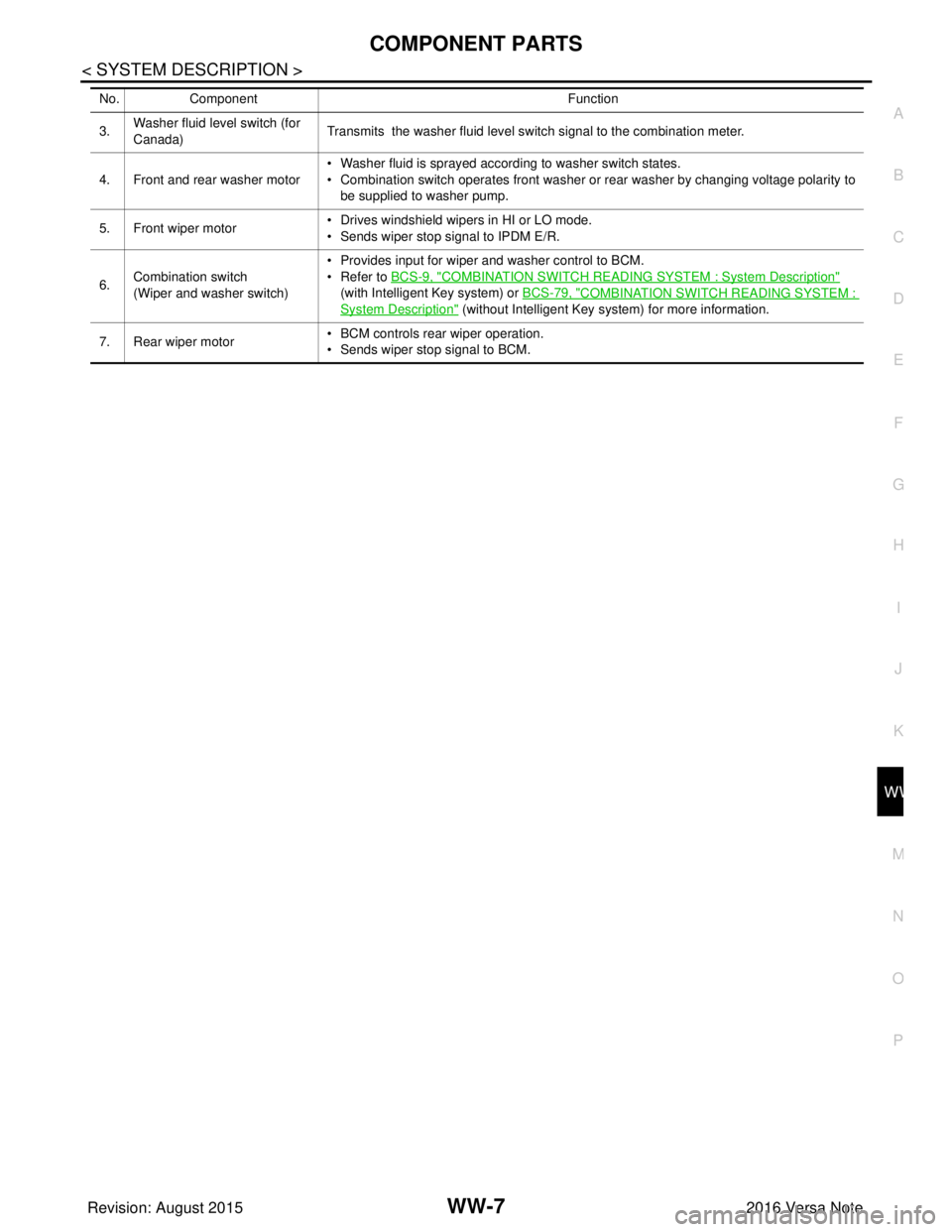
3. Washer fluid level switch (for
Canada) Transmits the washer fluid level switch signal to the combination meter.
4. Front and rear washer motor • Washer fluid is sprayed according to washer switch states.
• Combination switch operates front washer or rear washer by changing voltage polarity to
be supplied to washer pump.
5. Front wiper motor • Drives windshield wipers in HI or LO mode.
• Sends wiper stop signal to IPDM E/R.
6. Combination switch
(Wiper and washer switch) • Provides input for wiper and washer control to BCM.
• Refer to
BCS-9, "
COMBINATION SWITCH READING SYSTEM : System Description"
(with Intelligent Key system) or BCS-79, "
COMBINATION SWITCH READING SYSTEM :
System Description" (without Intelligent Key system) for more information.
7. Rear wiper motor • BCM controls rear wiper operation.
• Sends wiper stop signal to BCM.
No.
Component Function
Revision: August 2015 2016 Versa Note
cardiagn.com
Page 3573 of 3641
WW-8
< SYSTEM DESCRIPTION >
SYSTEM
SYSTEM
FRONT WIPER AND WASHER SYSTEM
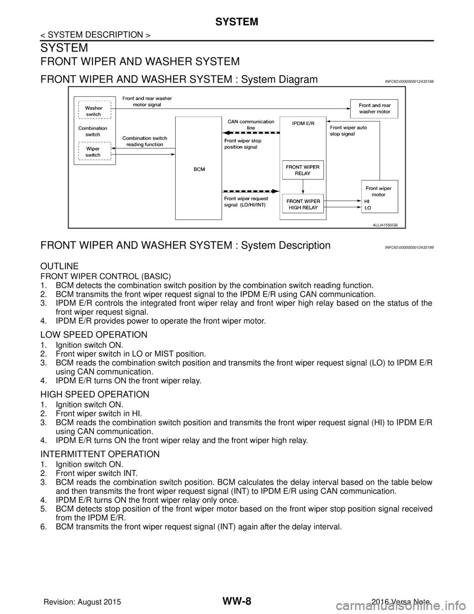
FRONT WIPER AND WASHER SYSTEM : System DiagramINFOID:0000000012433198
FRONT WIPER AND WASHER SYSTEM : System DescriptionINFOID:0000000012433199
OUTLINE
FRONT WIPER CONTROL (BASIC)
1. BCM detects the combination switch position by the combination switch reading function.
2. BCM transmits the front wiper request signal to the IPDM E/R using CAN communication.
3. IPDM E/R controls the integrated front wiper relay and front wiper high relay based on the status of the front wiper request signal.
4. IPDM E/R provides power to operate the front wiper motor.
LOW SPEED OPERATION
1. Ignition switch ON.
2. Front wiper switch in LO or MIST position.
3. BCM reads the combination switch position and transmi ts the front wiper request signal (LO) to IPDM E/R
using CAN communication.
4. IPDM E/R turns ON the front wiper relay.
HIGH SPEED OPERATION
1. Ignition switch ON.
2. Front wiper switch in HI.
3. BCM reads the combination switch position and transmits the front wiper request signal (HI) to IPDM E/R using CAN communication.
4. IPDM E/R turns ON the front wiper relay and the front wiper high relay.
INTERMITTENT OPERATION
1. Ignition switch ON.
2. Front wiper switch INT.
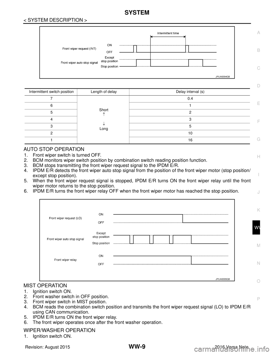
3. BCM reads the combination switch position. BCM ca lculates the delay interval based on the table below
and then transmits the front wiper request signal (INT) to IPDM E/R using CAN communication.
4. IPDM E/R turns ON the front wiper relay only once.
5. BCM detects stop position of the front wiper motor based on the front wiper stop position signal received from the IPDM E/R.
6. BCM transmits the front wiper request si gnal (INT) again after the delay interval.
ALLIA1550GB
Revision: August 2015 2016 Versa Note
cardiagn.com
Page 3574 of 3641
SYSTEMWW-9
< SYSTEM DESCRIPTION >
C
DE
F
G H
I
J
K
M A
B
WW
N
O P
AUTO STOP OPERATION
1. Front wiper switch is turned OFF.
2. BCM monitors wiper switch position by combination switch reading position function.
3. BCM stops transmitting the front wiper request signal to the IPDM E/R.
4. IPDM E/R detects the front wiper auto stop signal from the position of the front wiper motor (stop position/ except stop position).
5. When the front wiper request signal is stopped, IPDM E/R turns ON the front wiper relay until the front
wiper motor returns to the stop position.
6. IPDM E/R turns the front wiper relay OFF when the front wiper motor has reached the stop position.
MIST OPERATION
1. Ignition switch ON.
2. Front washer switch in OFF position.
3. Front wiper switch in MIST position.
4. BCM reads the combination switch position and transmits the front wiper request signal (LO) to IPDM E/R
using CAN communication.
5. IPDM E/R turns ON the front wiper relay.
6. The front wiper operates once after the front washer operation.
WIPER/WASHER OPERATION
1. Ignition switch ON.
JPLIA0094GB
Intermittent switch position Length of delay Delay interval (s)
7
Short↑
↓
Long 0.4
6 1
5 2
4 3
3 5
2 10
1 16
JPLIA0095GB
Revision: August 2015 2016 Versa Note
cardiagn.com
Page 3575 of 3641
WW-10
< SYSTEM DESCRIPTION >
SYSTEM
2. Front washer switch ON.
3. The front washer switch provides ground for the front and rear washer motor.
4. BCM reads the combination switch position and transmi ts the front wiper request signal (LO) to IPDM E/R
using CAN communication.
5. BCM transmits the front wiper request signal (LO) to IPDM E/R using CAN communication.
6. IPDM E/R turns ON the front wiper relay.
7. The front wiper operates.
NOTE:
BCM transmits the front wiper request signal (LO) so t hat the front wiper operates approximately 3 times after
front washer switch OFF is detected.
FRONT WIPER AND WASHER SYSTEM : Fail-SafeINFOID:0000000012433200
FA I L −SAFE OPERATION
IPDM E/R performs the fail-safe function when the front wiper auto stop circuit is malfunctioning. Refer to
PCS-19, "
Fail-safe".
REAR WIPER AND WASHER SYSTEM
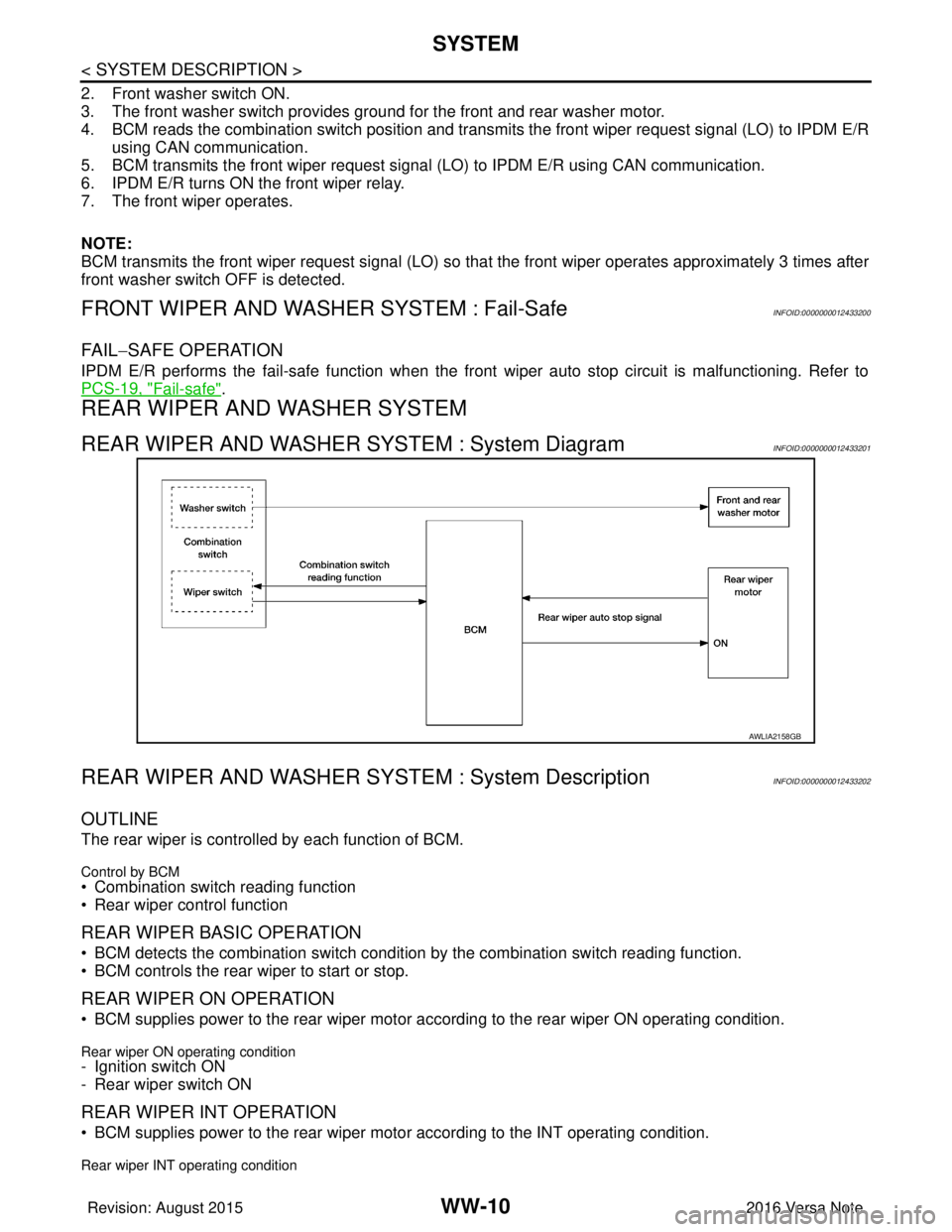
REAR WIPER AND WASHER SYSTEM : System DiagramINFOID:0000000012433201
REAR WIPER AND WASHER SY STEM : System DescriptionINFOID:0000000012433202
OUTLINE
The rear wiper is controlled by each function of BCM.
Control by BCM
• Combination switch reading function
• Rear wiper control function
REAR WIPER BASIC OPERATION
• BCM detects the combination switch conditi on by the combination switch reading function.
• BCM controls the rear wiper to start or stop.
REAR WIPER ON OPERATION
• BCM supplies power to the rear wiper motor ac cording to the rear wiper ON operating condition.
Rear wiper ON operating condition- Ignition switch ON
- Rear wiper switch ON
REAR WIPER INT OPERATION
• BCM supplies power to the rear wiper motor according to the INT operating condition.
Rear wiper INT operating condition
AWLIA2158GB
Revision: August 2015 2016 Versa Note
cardiagn.com
Page 3578 of 3641

DIAGNOSIS SYSTEM (BCM) (WITH INTELLIGENT KEY SYSTEM)
WW-13
< SYSTEM DESCRIPTION >
C
D E
F
G H
I
J
K
M A
B
WW
N
O P
DIAGNOSIS SYSTEM (BCM) (WIT H INTELLIGENT KEY SYSTEM)
COMMON ITEM
COMMON ITEM : CONSULT Function (BCM - COMMON ITEM)INFOID:0000000012542535
APPLICATION ITEM
CONSULT performs the following functions via CAN communication with BCM.
SYSTEM APPLICATION
BCM can perform the following functions.
Direct Diagnostic Mode Description
ECU Identification The BCM part number is displayed.
Self Diagnostic Result The BCM self diagnostic results are displayed.
Data Monitor The BCM input/output data is displayed in real time.
Active Test The BCM activates outputs to test components.
Work support The settings for BCM functions can be changed.
Configuration • The vehicle specification can be read and saved.
• The vehicle specification can be written when replacing BCM.
CAN DIAG SUPPORT MNTR The result of transmit/receive diagnosis of CAN communication is displayed.
System Sub System Direct Diagnostic Mode
ECU Identification
Self Diagnostic Result
Data Monitor
Active Test
Work support
Configuration
CAN DIAG SUPPORT MNTR
Door lock
DOOR LOCK ×××
Rear window defogger REAR DEFOGGER ××
Warning chime BUZZER ××
Interior room lamp timer INT LAMP ×××
Exterior lamp HEAD LAMP ×××
Wiper and washer WIPER ×××
Turn signal and hazard warning lamps FLASHER ×××
Air conditioner AIR CONDITIONER ×
Intelligent Key system INTELLIGENT KEY ××××
Combination switch COMB SW ×
BCM BCM× × ×××
Immobilizer IMMU ××××
Interior room lamp battery saver BATTERY SAVER ×××
Vehicle security system THEFT ALM ××
RAP system RETAINED PWR ×
Signal buffer system SIGNAL BUFFER ×
TPMS AIR PRESSURE MONITOR ××××
Panic alarm system PANIC ALARM ×
Revision: August 2015 2016 Versa Note
cardiagn.com
Page 3580 of 3641

DIAGNOSIS SYSTEM (BCM) (WITHOUT INTELLIGENT KEY SYSTEM)WW-15
< SYSTEM DESCRIPTION >
C
DE
F
G H
I
J
K
M A
B
WW
N
O P
DIAGNOSIS SYSTEM (BCM) (WITHO UT INTELLIGENT KEY SYSTEM)
COMMON ITEM
COMMON ITEM : CONSULT Function (BCM - COMMON ITEM)INFOID:0000000012542537
APPLICATION ITEM
CONSULT performs the following functions via CAN communication with BCM.
SYSTEM APPLICATION
BCM can perform the following functions.
Direct Diagnostic Mode Description
ECU Identification The BCM part number is displayed.
Self Diagnostic Result The BCM self diagnostic results are displayed.
Data Monitor The BCM input/output data is displayed in real time.
Active Test The BCM activates outputs to test components.
Work support The settings for BCM functions can be changed.
Configuration • The vehicle specification can be read and saved.
• The vehicle specification can be written when replacing BCM.
CAN DIAG SUPPORT MNTR The result of transmit/receive diagnosis of CAN communication is displayed.
System Sub System Direct Diagnostic Mode
ECU Identification
Self Diagnostic Result
Data Monitor
Active Test
Work support
Configuration
CAN DIAG SUPPORT MNTR
Door lock
DOOR LOCK ×××
Rear window defogger REAR DEFOGGER ××
Warning chime BUZZER ××
Interior room lamp timer INT LAMP ×××
Remote keyless entry system MULTI REMOTE ENT ×××
Exterior lamp HEAD LAMP ×××
Wiper and washer WIPER ×××
Turn signal and hazard warning lamps FLASHER ××
Air conditioner AIR CONDITIONER ×
Combination switch COMB SW ×
BCM BCM× × ×××
Immobilizer IMMU ×××
Interior room lamp battery saver BATTERY SAVER ×××
Vehicle security system THEFT ALM ××
RAP system RETAINED PWR ××
Signal buffer system SIGNAL BUFFER ×
TPMS AIR PRESSURE MONITOR ××××
Panic alarm system PANIC ALARM ×
Revision: August 2015 2016 Versa Note
cardiagn.com
Page 3583 of 3641
WW-18
< SYSTEM DESCRIPTION >
DIAGNOSIS SYSTEM (IPDM E/R)
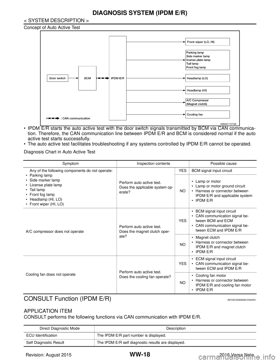
Concept of Auto Active Test
• IPDM E/R starts the auto active test with the door switch signals transmitted by BCM via CAN communica-
tion. Therefore, the CAN communication line between IPDM E/R and BCM is considered normal if the auto
active test starts successfully.
• The auto active test facilitates troubleshooting if any systems controlled by IPDM E/R cannot be operated.
Diagnosis Chart in Auto Active Test
CONSULT Function (IPDM E/R)INFOID:0000000012542541
APPLICATION ITEM
CONSULT performs the following functions via CAN communication with IPDM E/R.
AWMIA1737GB
Symptom Inspection contentsPossible cause
Any of the following components do not operate:
•Parking lamp
• Side marker lamp
• License plate lamp
•Tail lamp
• Front fog lamp
• Headlamp (HI, LO)
• Front wiper (HI, LO) Perform auto active test.
Does the applicable system op-
erate?YES BCM signal input circuit
NO • Lamp or motor
• Lamp or motor ground circuit
• Harness or connector between
IPDM E/R and applicable system
• IPDM E/R
A/C compressor does not operate Perform auto active test.
Does the magnet clutch oper-
ate?YES
• BCM signal input circuit
• CAN communication signal be-
tween BCM and ECM
• CAN communication signal be-
tween ECM and IPDM E/R
NO • Magnet clutch
• Harness or connector between
IPDM E/R and magnet clutch
• IPDM E/R
Cooling fan does not operate Perform auto active test.
Does the cooling fan operate?YES
• ECM signal input circuit
• CAN communication signal be-
tween ECM and IPDM E/R
NO • Cooling fan motor
• Harness or connector between
IPDM E/R and cooling fan motor
• IPDM E/R
Direct Diagnostic Mode Description
ECU Identification The IPDM E/R part number is displayed.
Self Diagnostic Result The IPDM E/R self diagnostic results are displayed.
Revision: August 2015 2016 Versa Note
cardiagn.com