2016 NISSAN NOTE change time
[x] Cancel search: change timePage 1661 of 3641

SYSTEMEXL-9
< SYSTEM DESCRIPTION >
C
DE
F
G H
I
J
K
M A
B
EXL
N
O P
Under this condition, the headlamps remain illuminated for 45 seconds unless the lighting switch position is
changed. If the lighting switch position is changed, then the headlamps are turned off.
This setting can be changed by CONSULT. Refer to BCS-20, "
HEADLAMP : CONSULT Function (BCM -
HEAD LAMP)" (with Intelligent Key system) or BCS-93, "HEADLAMP : CONSULT Function (BCM - HEAD
LAMP)" (without Intelligent Key system).
DAYTIME RUNNING LIGHT SYSTEM
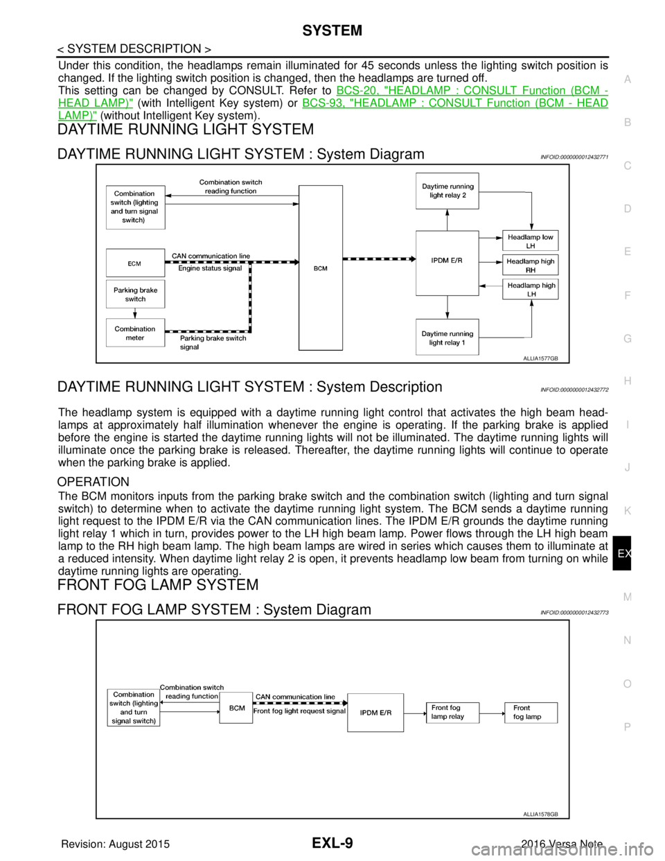
DAYTIME RUNNING LIGHT SYSTEM : System DiagramINFOID:0000000012432771
DAYTIME RUNNING LIGHT SYST EM : System DescriptionINFOID:0000000012432772
The headlamp system is equipped with a daytime running light control that activates the high beam head-
lamps at approximately half illumination whenever the e ngine is operating. If the parking brake is applied
before the engine is started the daytime running lights will not be illuminated. The daytime running lights will
illuminate once the parking brake is released. Thereaf ter, the daytime running lights will continue to operate
when the parking brake is applied.
OPERATION
The BCM monitors inputs from the parking brake swit ch and the combination switch (lighting and turn signal
switch) to determine when to activate the daytime running light system. The BCM sends a daytime running
light request to the IPDM E/R via the CAN communication lines. The IPDM E/R grounds the daytime running
light relay 1 which in turn, provides power to the LH high beam lamp. Power flows through the LH high beam
lamp to the RH high beam lamp. The high beam lamps are wired in series which causes them to illuminate at
a reduced intensity. When daytime light relay 2 is open, it prevents headlamp low beam from turning on while
daytime running lights are operating.
FRONT FOG LAMP SYSTEM
FRONT FOG LAMP SYSTEM : System DiagramINFOID:0000000012432773
ALLIA1577GB
ALLIA1578GB
Revision: August 2015 2016 Versa Note
cardiagn.com
Page 1664 of 3641

EXL-12
< SYSTEM DESCRIPTION >
DIAGNOSIS SYSTEM (BCM) (WITH INTELLIGENT KEY SYSTEM)
DIAGNOSIS SYSTEM (BCM) (WITH INTELLIGENT KEY SYSTEM)
COMMON ITEM
COMMON ITEM : CONSULT Function (BCM - COMMON ITEM)INFOID:0000000012542302
APPLICATION ITEM
CONSULT performs the following functions via CAN communication with BCM.
SYSTEM APPLICATION
BCM can perform the following functions.
Direct Diagnostic Mode Description
ECU Identification The BCM part number is displayed.
Self Diagnostic Result The BCM self diagnostic results are displayed.
Data Monitor The BCM input/output data is displayed in real time.
Active Test The BCM activates outputs to test components.
Work support The settings for BCM functions can be changed.
Configuration • The vehicle specification can be read and saved.
• The vehicle specification can be written when replacing BCM.
CAN DIAG SUPPORT MNTR The result of transmit/receive diagnosis of CAN communication is displayed.
System Sub System Direct Diagnostic Mode
ECU Identification
Self Diagnostic Result
Data Monitor
Active Test
Work support
Configuration
CAN DIAG SUPPORT MNTR
Door lock
DOOR LOCK ×××
Rear window defogger REAR DEFOGGER ××
Warning chime BUZZER ××
Interior room lamp timer INT LAMP ×××
Exterior lamp HEAD LAMP ×××
Wiper and washer WIPER ×××
Turn signal and hazard warning lamps FLASHER ×××
Air conditioner AIR CONDITIONER ×
Intelligent Key system INTELLIGENT KEY ××××
Combination switch COMB SW ×
BCM BCM× × ×××
Immobilizer IMMU ××××
Interior room lamp battery saver BATTERY SAVER ×××
Vehicle security system THEFT ALM ××
RAP system RETAINED PWR ×
Signal buffer system SIGNAL BUFFER ×
TPMS AIR PRESSURE MONITOR ××××
Panic alarm system PANIC ALARM ×
Revision: August 2015 2016 Versa Note
cardiagn.com
Page 1668 of 3641

EXL-16
< SYSTEM DESCRIPTION >
DIAGNOSIS SYSTEM (BCM) (WITHOUT INTELLIGENT KEY SYSTEM)
DIAGNOSIS SYSTEM (BCM) (WITHOUT INTELLIGENT KEY SYSTEM)
COMMON ITEM
COMMON ITEM : CONSULT Function (BCM - COMMON ITEM)INFOID:0000000012542311
APPLICATION ITEM
CONSULT performs the following functions via CAN communication with BCM.
SYSTEM APPLICATION
BCM can perform the following functions.
Direct Diagnostic Mode Description
ECU Identification The BCM part number is displayed.
Self Diagnostic Result The BCM self diagnostic results are displayed.
Data Monitor The BCM input/output data is displayed in real time.
Active Test The BCM activates outputs to test components.
Work support The settings for BCM functions can be changed.
Configuration • The vehicle specification can be read and saved.
• The vehicle specification can be written when replacing BCM.
CAN DIAG SUPPORT MNTR The result of transmit/receive diagnosis of CAN communication is displayed.
System Sub System Direct Diagnostic Mode
ECU Identification
Self Diagnostic Result
Data Monitor
Active Test
Work support
Configuration
CAN DIAG SUPPORT MNTR
Door lock
DOOR LOCK ×××
Rear window defogger REAR DEFOGGER ××
Warning chime BUZZER ××
Interior room lamp timer INT LAMP ×××
Remote keyless entry system MULTI REMOTE ENT ×××
Exterior lamp HEAD LAMP ×××
Wiper and washer WIPER ×××
Turn signal and hazard warning lamps FLASHER ××
Air conditioner AIR CONDITIONER ×
Combination switch COMB SW ×
BCM BCM× × ×××
Immobilizer IMMU ×××
Interior room lamp battery saver BATTERY SAVER ×××
Vehicle security system THEFT ALM ××
RAP system RETAINED PWR ××
Signal buffer system SIGNAL BUFFER ×
TPMS AIR PRESSURE MONITOR ××××
Panic alarm system PANIC ALARM ×
Revision: August 2015 2016 Versa Note
cardiagn.com
Page 1787 of 3641

EXT-20
< SYMPTOM DIAGNOSIS >
SQUEAK AND RATTLE TROUBLE DIAGNOSES
1. Loose harness or harness connectors.
2. Front console map/reading lamp lens loose.
3. Loose screws at console attachment points.
SEATS
When isolating seat noise it's important to note the position the seat is in and the load placed on the seat when
the noise is present. These conditions should be duplicated when verifying and isolating the cause of the
noise.
Cause of seat noise include:
1. Headrest rods and holder
2. A squeak between the seat pad cushion and frame
3. The rear seatback lock and bracket
These noises can be isolated by moving or pressing on the suspected components while duplicating the con-
ditions under which the noise occurs. Most of thes e incidents can be repaired by repositioning the component
or applying urethane tape to the contact area.
UNDERHOOD
Some interior noise may be caused by components under the hood or on the engine wall. The noise is then
transmitted into the passenger compartment.
Causes of transmitted underhood noise include:
1. Any component installed to the engine wall
2. Components that pass through the engine wall
3. Engine wall mounts and connectors
4. Loose radiator installation pins
5. Hood bumpers out of adjustment
6. Hood striker out of adjustment
These noises can be difficult to isolate since they cannot be reached from the interior of the vehicle. The best
method is to secure, move or insulate one component at a time and test drive the vehicle. Also, engine rpm or
load can be changed to isolate the noise. Repairs can usually be made by moving, adjusting, securing, or
insulating the component causing the noise.
Revision: August 2015 2016 Versa Note
cardiagn.com
Page 1916 of 3641

GI-28
< PRECAUTION >
LIFTING POINT
LIFTING POINT
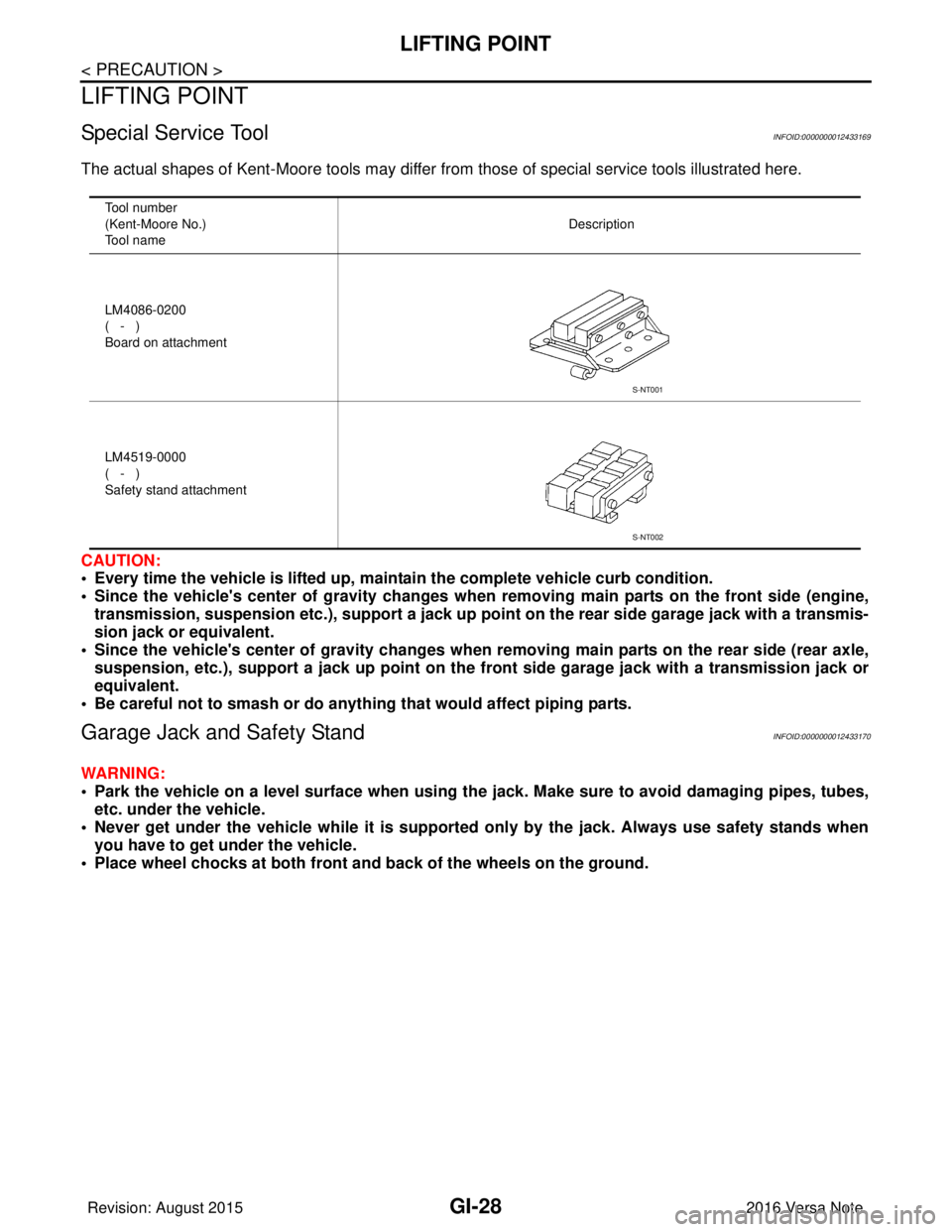
Special Service ToolINFOID:0000000012433169
The actual shapes of Kent-Moore tools may differ from those of special service tools illustrated here.
CAUTION:
• Every time the vehicle is lifted up, main tain the complete vehicle curb condition.
• Since the vehicle's center of gravity changes when removing main parts on the front side (engine, transmission, suspension etc.), supp ort a jack up point on the rear side garage jack with a transmis-
sion jack or equivalent.
• Since the vehicle's center of gravity changes when removing main parts on the rear side (rear axle,
suspension, etc.), support a jack up point on the front side garage jack with a transmission jack or
equivalent.
• Be careful not to smash or do anything that would affect piping parts.
Garage Jack and Safety StandINFOID:0000000012433170
WARNING:
• Park the vehicle on a level surface when using the jack. Make sure to avoid damaging pipes, tubes,
etc. under the vehicle.
• Never get under the vehicle while it is supported only by the jack. Always use safety stands when
you have to get under the vehicle.
• Place wheel chocks at both front an d back of the wheels on the ground.
Tool number
(Kent-Moore No.)
Tool name Description
LM4086-0200
( - )
Board on attachment
LM4519-0000
( - )
Safety stand attachment
S-NT001
S-NT002
Revision: August 2015 2016 Versa Note
cardiagn.com
Page 1938 of 3641

GI-50
< BASIC INSPECTION >
CONSULT/GST CHECKING SYSTEM
CONSULT/GST CHECKING SYSTEM
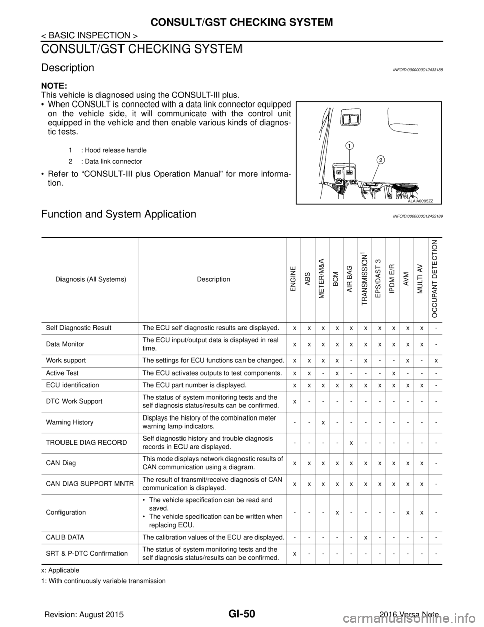
DescriptionINFOID:0000000012433188
NOTE:
This vehicle is diagnosed using the CONSULT-III plus.
• When CONSULT is connected with a data link connector equippedon the vehicle side, it will communicate with the control unit
equipped in the vehicle and then enable various kinds of diagnos-
tic tests.
• Refer to “CONSULT-III plus Operation Manual” for more informa- tion.
Function and System ApplicationINFOID:0000000012433189
x: Applicable
1: With continuously variable transmission 1 : Hood release handle
2 : Data link connector
ALAIA0095ZZ
Diagnosis (All Systems)
Description
ENGINE
ABS
METER/M&A BCM
AIR BAG
TRANSMISSION
1
EPS/DAST 3 IPDM E/R AV M
MULTI AV
OCCUPANT DETECTION
Self Diagnostic Result The ECU self diagnostic results are displayed. x x x x x x x x x x -
Data Monitor The ECU input/output data is displayed in real
time. xxxxxxxxxx -
Work support The settings for ECU functions can be changed. x x x x - x - - x - x
Active Test The ECU activates outputs to test components. x x - x - - - x - - -
ECU identification The ECU part number is displayed. xxxxxxxxxx -
DTC Work Support The status of system monitoring tests and the
self diagnosis status/results can be confirmed. x----------
Warning History Displays the history of the combination meter
warning lamp indicators.
--x--------
TROUBLE DIAG RECORD Self diagnostic history and trouble diagnosis
records in ECU are displayed. ----x------
CAN Diag This mode displays network diagnostic results of
CAN communication using a diagram. xxxxxxxxxx -
CAN DIAG SUPPORT MNTR The result of transmit/receive diagnosis of CAN
communication is displayed.
xxxxxxxxxx -
Configuration • The vehicle specification can be read and
saved.
• The vehicle specification can be written when
replacing ECU. ---x----xx-
CALIB DATA The calibration values of the ECU are displayed. - - - - - x - - - - -
SRT & P-DTC Confirmation The status of system monitoring tests and the
self diagnosis status/results can be confirmed. x----------
Revision: August 2015
2016 Versa Note
cardiagn.com
Page 1948 of 3641

GW-8
< SYMPTOM DIAGNOSIS >
SQUEAK AND RATTLE TROUBLE DIAGNOSES
1. Loose harness or harness connectors.
2. Front console map/reading lamp lens loose.
3. Loose screws at console attachment points.
SEATS
When isolating seat noise it's important to note the position the seat is in and the load placed on the seat when
the noise is present. These conditions should be duplicated when verifying and isolating the cause of the
noise.
Cause of seat noise include:
1. Headrest rods and holder
2. A squeak between the seat pad cushion and frame
3. The rear seatback lock and bracket
These noises can be isolated by moving or pressing on the suspected components while duplicating the con-
ditions under which the noise occurs. Most of thes e incidents can be repaired by repositioning the component
or applying urethane tape to the contact area.
UNDERHOOD
Some interior noise may be caused by components under the hood or on the engine wall. The noise is then
transmitted into the passenger compartment.
Causes of transmitted underhood noise include:
1. Any component installed to the engine wall
2. Components that pass through the engine wall
3. Engine wall mounts and connectors
4. Loose radiator installation pins
5. Hood bumpers out of adjustment
6. Hood striker out of adjustment
These noises can be difficult to isolate since they cannot be reached from the interior of the vehicle. The best
method is to secure, move or insulate one component at a time and test drive the vehicle. Also, engine rpm or
load can be changed to isolate the noise. Repairs can usually be made by moving, adjusting, securing, or
insulating the component causing the noise.
Revision: August 2015 2016 Versa Note
cardiagn.com
Page 1984 of 3641
![NISSAN NOTE 2016 Service Repair Manual HAC-16
< SYSTEM DESCRIPTION >[MANUAL AIR CONDITIONING]
OPERATION
OPERATION
Switch Name and FunctionINFOID:0000000012430720
CONTROLLER
SWITCH OPERATION
1. Fan control dial (fan switch) 2. MODE dial
3. NISSAN NOTE 2016 Service Repair Manual HAC-16
< SYSTEM DESCRIPTION >[MANUAL AIR CONDITIONING]
OPERATION
OPERATION
Switch Name and FunctionINFOID:0000000012430720
CONTROLLER
SWITCH OPERATION
1. Fan control dial (fan switch) 2. MODE dial
3.](/manual-img/5/57363/w960_57363-1983.png)
HAC-16
< SYSTEM DESCRIPTION >[MANUAL AIR CONDITIONING]
OPERATION
OPERATION
Switch Name and FunctionINFOID:0000000012430720
CONTROLLER
SWITCH OPERATION
1. Fan control dial (fan switch) 2. MODE dial
3. Intake lever
4. Temperature control dial 5. A/C switch
AWLIA2419ZZ
Fan control dial (fan switch) Fan speed can be adjusted within a range from 1st to 4th.
MODE dialMode position is selected to an optimal position by operating this dial.
Intake lever The air inlet changes REC ⇔ FRE each time by operation this lever.
Temperature control dial The setting temperature can be selected to an optimum temperature by operating this dial.
A/C switch The compressor control (switc
h indicator) is turned ON ⇔ OFF each time by pressing this switch while
the blower motor is activated.
Revision: August 2015 2016 Versa Note
cardiagn.com