2016 NISSAN NOTE ECU
[x] Cancel search: ECUPage 2555 of 3641
![NISSAN NOTE 2016 Service Repair Manual PCS-52
< BASIC INSPECTION >[POWER DISTRIBUTION SYSTEM]
DIAGNOSIS AND REPAIR WORK FLOW
8.REPAIR OR REPLACE THE MALFUNCTIONING PART
1. Repair or replace the malfunctioning part.
2. Reconnect parts or co NISSAN NOTE 2016 Service Repair Manual PCS-52
< BASIC INSPECTION >[POWER DISTRIBUTION SYSTEM]
DIAGNOSIS AND REPAIR WORK FLOW
8.REPAIR OR REPLACE THE MALFUNCTIONING PART
1. Repair or replace the malfunctioning part.
2. Reconnect parts or co](/manual-img/5/57363/w960_57363-2554.png)
PCS-52
< BASIC INSPECTION >[POWER DISTRIBUTION SYSTEM]
DIAGNOSIS AND REPAIR WORK FLOW
8.REPAIR OR REPLACE THE MALFUNCTIONING PART
1. Repair or replace the malfunctioning part.
2. Reconnect parts or connectors disconnected during Diagnosis Procedure again after repair and replace- ment.
3. Check DTC. If DTC is detected, erase it.
>> GO TO 9.
9.FINAL CHECK
When DTC is detected in step 2, perform DTC CONFIRMATION PROCEDURE again, and then check that the
malfunction is repaired securely.
When symptom is described by the customer, refer to confirmed symptom in step 3 or 4, and check that the
symptom is not detected.
Is DTC detected and does symptom remain?
YES-1 >> DTC is detected: GO TO 7.
YES-2 >> Symptom remains: GO TO 4.
NO >> Inspection End.
Revision: August 2015 2016 Versa Note
cardiagn.com
Page 2578 of 3641
![NISSAN NOTE 2016 Service Repair Manual PCS
PUSH-BUTTON IGNITION SWITCH DOES NOT OPERATEPCS-75
< SYMPTOM DIAGNOSIS > [POWER DISTRIBUTION SYSTEM]
C
D
E
F
G H
I
J
K L
B A
O P
N
SYMPTOM DIAGNOSIS
PUSH-BUTTON IGNITION SW
ITCH DOES NOT OPERATE
D NISSAN NOTE 2016 Service Repair Manual PCS
PUSH-BUTTON IGNITION SWITCH DOES NOT OPERATEPCS-75
< SYMPTOM DIAGNOSIS > [POWER DISTRIBUTION SYSTEM]
C
D
E
F
G H
I
J
K L
B A
O P
N
SYMPTOM DIAGNOSIS
PUSH-BUTTON IGNITION SW
ITCH DOES NOT OPERATE
D](/manual-img/5/57363/w960_57363-2577.png)
PCS
PUSH-BUTTON IGNITION SWITCH DOES NOT OPERATEPCS-75
< SYMPTOM DIAGNOSIS > [POWER DISTRIBUTION SYSTEM]
C
D
E
F
G H
I
J
K L
B A
O P
N
SYMPTOM DIAGNOSIS
PUSH-BUTTON IGNITION SW
ITCH DOES NOT OPERATE
DescriptionINFOID:0000000012433320
Check that vehicle Operating Conditions are as listed in “Conditions of Vehicle” below before starting Diagno-
sis Procedure. Make sure to chec k each symptom in Diagnosis Procedure.
NOTE:
The engine start function, door lock function, power distribution system, and NATS-NVIS in the Intelligent Key
system are closely related to each other regarding c ontrol. The vehicle security function can operate only
when the door lock and power distribut ion system are operating normally.
Conditions of Vehicle (Operating Conditions)
• ENGINE START BY I-KEY in “Work support” is set to On. Refer to BCS-22, "INTELLIGENT KEY : CON-
SULT Function (BCM - INTELLIGENT KEY)".
• One or more of Intelligent Keys with registered Intelligent Key ID is in the vehicle.
Diagnosis ProcedureINFOID:0000000012433321
1.PERFORM WORK SUPPORT
Perform INSIDE ANT DIAGNOSIS in “Work Support” of “INTELLIGENT KEY” using CONSULT. Refer to BCS-
22, "INTELLIGENT KEY : CONSULT Func tion (BCM - INTELLIGENT KEY)".
>> GO TO 2.
2.PERFORM SELF DIAGNOSTIC RESULT
Perform “Self Diagnostic Result” of “BCM” using CONSULT.
Are any DTCs detected?
YES >> Refer to BCS-50, "DTCIndex".
NO >> GO TO 3.
3.CHECK PUSH-BUTTON IGNITION SWITCH
Check push-button ignition switch. Refer to PCS-71, "
Component Inspection".
Is the inspection result normal?
YES >> Refer to GI-42, "Intermittent Incident".
NO >> Repair or replace malfunctioning parts.
Revision: August 2015 2016 Versa Note
cardiagn.com
Page 2582 of 3641
PWO-2
< PRECAUTION >
PRECAUTIONS
PRECAUTION
PRECAUTIONS
Precaution for Supplemental Restraint System (SRS) "AIR BAG" and "SEAT BELT
PRE-TENSIONER"
INFOID:0000000012432097
The Supplemental Restraint System such as “A IR BAG” and “SEAT BELT PRE-TENSIONER”, used along
with a front seat belt, helps to reduce the risk or severity of injury to the driver and front passenger for certain
types of collision. Information necessary to service the system safely is included in the SR and SB section of
this Service Manual.
WARNING:
• To avoid rendering the SRS inopera tive, which could increase the risk of personal injury or death in
the event of a collision which would result in air bag inflation, all maintenance must be performed by
an authorized NISSAN/INFINITI dealer.
• Improper maintenance, including in correct removal and installation of the SRS, can lead to personal
injury caused by unintent ional activation of the system. For re moval of Spiral Cable and Air Bag
Module, see the SR section.
• Do not use electrical test equipmen t on any circuit related to the SRS unless instructed to in this
Service Manual. SRS wiring harn esses can be identified by yellow and/or orange harnesses or har-
ness connectors.
PRECAUTIONS WHEN USING POWER TOOLS (AIR OR ELECTRIC) AND HAMMERS
WARNING:
• When working near the Airbag Diagnosis Sensor Unit or other Airbag System sensors with the Igni-
tion ON or engine running, DO NOT use air or electri c power tools or strike near the sensor(s) with a
hammer. Heavy vibration could activate the sensor( s) and deploy the air bag(s), possibly causing
serious injury.
• When using air or electric power tools or hammers , always switch the Ignition OFF, disconnect the
battery and wait at least three minutes before performing any service.
Precaution for WorkINFOID:0000000012432098
• When removing or disassembling each component, be careful not to damage or deform it. If a component may be subject to interference, be sure to protect it with a shop cloth.
• When removing (disengaging) components with a screwdriver or similar tool, be sure to wrap the component with a shop cloth or vinyl tape to protect it.
• Protect the removed parts with a shop cloth and prevent them from being dropped.
• Replace a deformed or damaged clip.
• If a part is specified as a non-reusable part, always replace it with a new one.
• Be sure to tighten bolts and nuts securely to the specified torque.
• After installation is complete, be sure to check that each part works properly.
• Follow the steps below to clean components:
- Water soluble dirt:
• Dip a soft cloth into lukewarm water, wring the water out of the cloth and wipe the dirty area.
• Then rub with a soft, dry cloth.
- Oily dirt:
• Dip a soft cloth into lukewarm water with mild detergent (concentration: within 2 to 3%) and wipe the dirty area.
• Then dip a cloth into fresh water, wring the water out of the cloth and wipe the detergent off.
• Then rub with a soft, dry cloth.
- Do not use organic solvent such as thinner, benzene, alcohol or gasoline.
- For genuine leather seats, use a genuine leather seat cleaner.
Revision: August 2015 2016 Versa Note
cardiagn.com
Page 2657 of 3641
PG-70
< REMOVAL AND INSTALLATION >
BATTERY
REMOVAL AND INSTALLATION
BATTERY
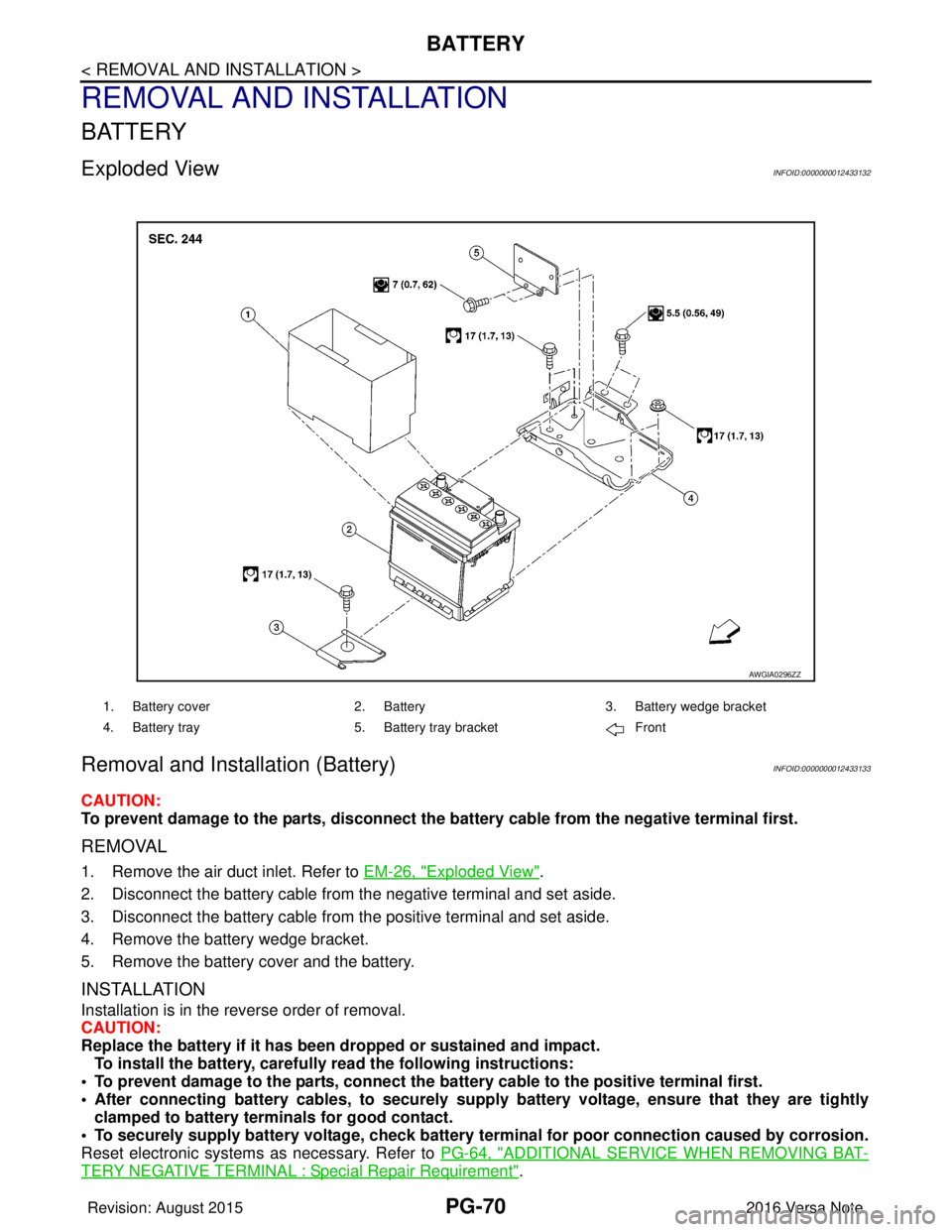
Exploded ViewINFOID:0000000012433132
Removal and Installation (Battery)INFOID:0000000012433133
CAUTION:
To prevent damage to the parts, disconnect the battery cable from the negative terminal first.
REMOVAL
1. Remove the air duct inlet. Refer to EM-26, "Exploded View".
2. Disconnect the battery cable from the negative terminal and set aside.
3. Disconnect the battery cable from the positive terminal and set aside.
4. Remove the battery wedge bracket.
5. Remove the battery cover and the battery.
INSTALLATION
Installation is in the reverse order of removal.
CAUTION:
Replace the battery if it has been dropped or sustained and impact. To install the battery, carefully read the following instructions:
• To prevent damage to the parts, connect the battery cable to the positive terminal first.
• After connecting battery cables, to securely supply battery voltage, ensure that they are tightly
clamped to battery term inals for good contact.
• To securely supply battery voltage, check battery terminal for poor connection caused by corrosion.
Reset electronic systems as necessary. Refer to PG-64, "
ADDITIONAL SERVICE WHEN REMOVING BAT-
TERY NEGATIVE TERMINAL : Special Repair Requirement".
AWGIA0296ZZ
1. Battery cover2. Battery3. Battery wedge bracket
4. Battery tray 5. Battery tray bracket Front
Revision: August 2015 2016 Versa Note
cardiagn.com
Page 2658 of 3641
PG
BATTERYPG-71
< REMOVAL AND INSTALLATION >
C
DE
F
G H
I
J
K L
B A
O P
N
Removal and Installation (Battery Tray)INFOID:0000000012433134
CAUTION:
To prevent damage to the parts, disconnect the battery cable from the negative terminal first.
REMOVAL
1. Remove the battery. Refer to
PG-70, "Removal and Installation (Battery)".
2. Remove the battery tray bracket. Refer to PG-70, "
Exploded View".
3. Remove the IPDM E/R. Refer to PCS-30, "
Removal and Installation".
4. Disconnect the harness from the TCM and remove the TCM bracket. Refer to TM-239, "
Removal and
Installation" (FOR CVT MODEL).
5. Disconnect the harness fr om the battery tray.
6. Remove the nuts and bolts and remove the battery tray. Refer to PG-70, "
Exploded View".
INSTALLATION
Installation is in the reverse order of removal.
CAUTION:
Replace electrical components as necessary, if any have been dropped or sustained and impact.
To install the battery, carefully read the following instructions:
• To prevent damage to the parts, connect the battery cable to the positive terminal first.
• After connecting battery cables, to securely supp ly battery voltage, ensure that they are tightly
clamped to battery terminals for good contact.
• To securely supply battery voltage, check battery terminal for poor connection caused by corrosion.
Reset electronic systems as necessary. Refer to PG-64, "
ADDITIONAL SERVICE WHEN REMOVING BAT-
TERY NEGATIVE TERMINAL : Special Repair Requirement".
Revision: August 2015 2016 Versa Note
cardiagn.com
Page 2659 of 3641
PG-72
< REMOVAL AND INSTALLATION >
BATTERY TERMINAL WITH FUSIBLE LINK
BATTERY TERMINAL WITH FUSIBLE LINK
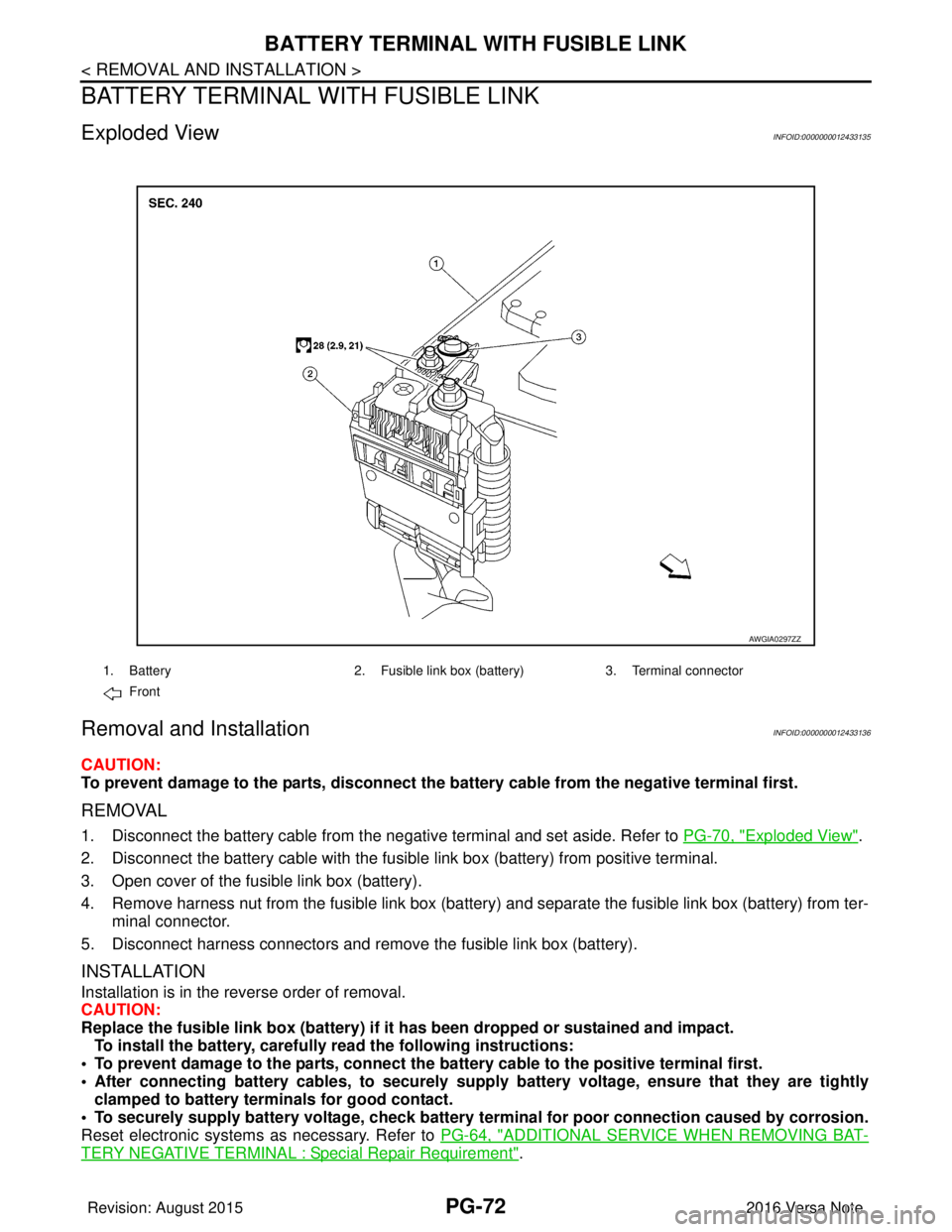
Exploded ViewINFOID:0000000012433135
Removal and InstallationINFOID:0000000012433136
CAUTION:
To prevent damage to the parts, disconnect the battery cable from the negative terminal first.
REMOVAL
1. Disconnect the battery cable from the negative terminal and set aside. Refer to PG-70, "Exploded View".
2. Disconnect the battery cable with the fusibl e link box (battery) from positive terminal.
3. Open cover of the fusible link box (battery).
4. Remove harness nut from the fusible link box (battery ) and separate the fusible link box (battery) from ter-
minal connector.
5. Disconnect harness connectors and remove the fusible link box (battery).
INSTALLATION
Installation is in the reverse order of removal.
CAUTION:
Replace the fusible link box (battery) if it has been dropped or sustained and impact.
To install the battery, carefully read the following instructions:
• To prevent damage to the parts, connect the battery cable to the positive terminal first.
• After connecting battery cables, to securely supply battery voltage, ensure that they are tightly
clamped to battery term inals for good contact.
• To securely supply battery voltage, check battery terminal for poor connection caused by corrosion.
Reset electronic systems as necessary. Refer to PG-64, "
ADDITIONAL SERVICE WHEN REMOVING BAT-
TERY NEGATIVE TERMINAL : Special Repair Requirement".
AWGIA0297ZZ
1. Battery2. Fusible link box (battery) 3. Terminal connector
Front
Revision: August 2015 2016 Versa Note
cardiagn.com
Page 2660 of 3641
PG
BATTERY CURRENT SENSORPG-73
< REMOVAL AND INSTALLATION >
C
DE
F
G H
I
J
K L
B A
O P
N
BATTERY CURRENT SENSOR
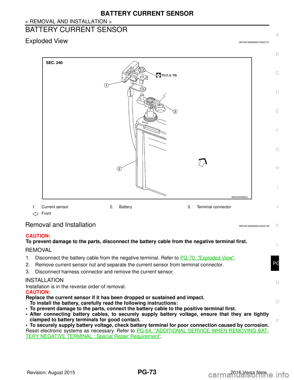
Exploded ViewINFOID:0000000012433137
Removal and InstallationINFOID:0000000012433138
CAUTION:
To prevent damage to the parts, disconnect the battery cable from the negative terminal first.
REMOVAL
1. Disconnect the battery cable from
the negative terminal. Refer to PG-70, "Exploded View".
2. Remove current sensor nut and separate the current sensor from terminal connector.
3. Disconnect harness connector and remove the current sensor.
INSTALLATION
Installation is in the reverse order of removal.
CAUTION:
Replace the current sensor if it has b een dropped or sustained and impact.
To install the battery, carefully read the following instructions:
• To prevent damage to the parts, connect the battery cable to the positive terminal first.
• After connecting battery cables, to securely supp ly battery voltage, ensure that they are tightly
clamped to battery terminals for good contact.
• To securely supply battery voltage, check battery terminal for poor connection caused by corrosion.
Reset electronic systems as necessary. Refer to PG-64, "
ADDITIONAL SERVICE WHEN REMOVING BAT-
TERY NEGATIVE TERMINAL : Special Repair Requirement".
AWGIA0298ZZ
1. Current sensor2. Battery3. Terminal connector
Front
Revision: August 2015 2016 Versa Note
cardiagn.com
Page 2662 of 3641

PWC-1
BODY EXTERIOR, DOORS, ROOF & VEHICLE SECURITY
C
DE
F
G H
I
J
L
M
SECTION PWC
A
B
PWC
N
O P
CONTENTS
POWER WINDOW CONTROL SYSTEM
PRECAUTION ....... ........................................4
PRECAUTIONS .............................................. .....4
Precaution for Supplemental Restraint System
(SRS) "AIR BAG" and "SEAT BELT PRE-TEN-
SIONER" ............................................................. ......
4
Precaution for Work ..................................................4
PREPARATION ............................................5
PREPARATION .............................................. .....5
Special Service Tool ........................................... ......5
SYSTEM DESCRIPTION ..............................6
COMPONENT PARTS ................................... .....6
Component Parts Location .................................. ......6
Main Power Window And Door Lock/Unlock
Switch ........................................................................
7
Power Window Switch ...............................................7
Power Window Motor ................................................7
SYSTEM ..............................................................8
System Description ............................................. ......8
DIAGNOSIS SYSTEM (BCM) (WITH INTELLI-
GENT KEY SYSTEM) ..........................................
9
COMMON ITEM ..................................................... ......9
COMMON ITEM : CONSULT Function (BCM -
COMMON ITEM) .......................................................
9
RETAINED PWR .......................................................10
RETAINED PWR : CONSULT Function (BCM -
RETAINED PWR) ...................................................
10
DIAGNOSIS SYSTEM (BCM) (WITHOUT IN-
TELLIGENT KEY SYSTEM) ...............................
11
COMMON ITEM ..................................................... ....11
COMMON ITEM : CONSULT Function (BCM -
COMMON ITEM) .....................................................
11
RETAINED PWR .................................................... ....12
RETAINED PWR : CONSULT Function (BCM -
RETAINED PWR) ....................................................
12
ECU DIAGNOSIS INFORMATION ..............13
BCM ...................................................................13
List of ECU Reference ......................................... ....13
POWER WINDOW MAIN SWITCH ...................14
Reference Value ......................................................14
Fail Safe ..................................................................15
WIRING DIAGRAM ......................................16
POWER WINDOW SYSTEM .............................16
Wiring Diagram .................................................... ....16
BASIC INSPECTION ...................................23
DIAGNOSIS AND REPAIR WORK FLOW .......23
Work Flow ............................................................ ....23
DTC/CIRCUIT DIAGNOSIS .........................25
POWER SUPPLY AND GROUND CIRCUIT . ...25
BCM (BODY CONTROL SYSTEM) (WITH INTEL-
LIGENT KEY SYSTEM) ........
.....................................
25
BCM (BODY CONTROL SYSTEM) (WITH INTEL-
LIGENT KEY SYSTEM) : Diagnosis Procedure .. ....
25
BCM (BODY CONTROL SYSTEM) (WITHOUT IN-
TELLIGENT KEY SYSTEM) .................................. ....
25
BCM (BODY CONTROL SYSTEM) (WITHOUT
INTELLIGENT KEY SYSTEM) : Diagnosis Proce-
dure ..................................................................... ....
25
POWER WINDOW MAIN SWITCH ........................ ....26
POWER WINDOW MAIN SWITCH : Diagnosis
Procedure ................................................................
26
FRONT POWER WINDOW SWITCH (PASSEN-
GER SIDE) .................................................................
27
Revision: August 2015 2016 Versa Note
cardiagn.com