2016 NISSAN NOTE transmission fluid
[x] Cancel search: transmission fluidPage 1902 of 3641

GI-14
< HOW TO USE THIS MANUAL >
ABBREVIATIONS
ABBREVIATIONS
Abbreviation ListINFOID:0000000012433154
The following ABBREVIATIONS are used:
A
B
C
D
ABBREVIATION DESCRIPTION
A/C Air conditioner
A/C Air conditioning
A/F sensor Air fuel ratio sensor A/T Automatic transaxle/transmission
ABS Anti-lock braking system
ACCS Advance climate control system ACL Air cleaner
AP Accelerator pedal
APP Accelerator pedal position
ATF Automatic transmission fluid
AV Audio visual
AVM Around view monitor
AWD All wheel drive
ABBREVIATION DESCRIPTION
BARO Barometric pressure BCI Backup collision intervention
BCM Body control module
BLSD Brake limited slip differential
BPP Brake pedal position
BSI Blind spot intervention
BSW Blind spot warning
ABBREVIATION DESCRIPTION
CKP Crankshaft position
CL Closed loop
CMP Camshaft position
CPP Clutch pedal position
CTP Closed throttle position
CVT Continuously variable transaxle/transmission
ABBREVIATION DESCRIPTION
D
1Drive range first gear
D
2Drive range second gear
D
3Drive range third gear
D
4Drive range fourth gear
DCA Distance control assist
DDS Downhill drive support
DFI Direct fuel injection system
Revision: August 2015 2016 Versa Note
cardiagn.com
Page 1912 of 3641
GI-24
< PRECAUTION >
PRECAUTIONS
General Precautions
INFOID:0000000012433162
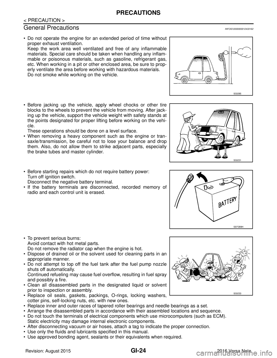
• Do not operate the engine for an extended period of time without proper exhaust ventilation.
Keep the work area well ventilated and free of any inflammable
materials. Special care should be taken when handling any inflam-
mable or poisonous materials, such as gasoline, refrigerant gas,
etc. When working in a pit or other enclosed area, be sure to prop-
erly ventilate the area before working with hazardous materials.
Do not smoke while working on the vehicle.
• Before jacking up the vehicle, apply wheel chocks or other tire blocks to the wheels to prevent the vehicle from moving. After jack-
ing up the vehicle, support the vehicle weight with safety stands at
the points designated for proper lifting before working on the vehi-
cle.
These operations should be done on a level surface.
• When removing a heavy component such as the engine or tran- saxle/transmission, be careful not to lose your balance and drop
them. Also, do not allow them to strike adjacent parts, especially
the brake tubes and master cylinder.
• Before starting repairs which do not require battery power: Turn off ignition switch.
Disconnect the negative battery terminal.
• If the battery terminals are disconnected, recorded memory of radio and each control unit is erased.
• To prevent serious burns: Avoid contact with hot metal parts.
Do not remove the radiator cap when the engine is hot.
• Dispose of drained oil or the solvent used for cleaning parts in an appropriate manner.
• Do not attempt to top off the fuel tank after the fuel pump nozzle
shuts off automatically.
Continued refueling may cause fuel overflow, resulting in fuel spray
and possibly a fire.
• Clean all disassembled parts in the designated liquid or solvent prior to inspection or assembly.
• Replace oil seals, gaskets, packings, O-rings, locking washers,
cotter pins, self-locking nuts, etc. with new ones.
• Replace inner and outer races of tapered roller bearings and needle bearings as a set.
• Arrange the disassembled parts in accordance with their assembled locations and sequence.
• Do not touch the terminals of electrical com ponents which use microcomputers (such as ECM).
Static electricity may damage internal electronic components.
• After disconnecting vacuum or air hoses, atta ch a tag to indicate the proper connection.
• Use only the fluids and lubricants specified in this manual.
• Use approved bonding agent, sealants or their equivalents when required.
SGI285
SGI231
SEF289H
SGI233
Revision: August 2015 2016 Versa Note
cardiagn.com
Page 2324 of 3641
PERIODIC MAINTENANCEMA-9
< PERIODIC MAINTENANCE >
C
DE
F
G H
I
J
K L
M B
MA
N
O A
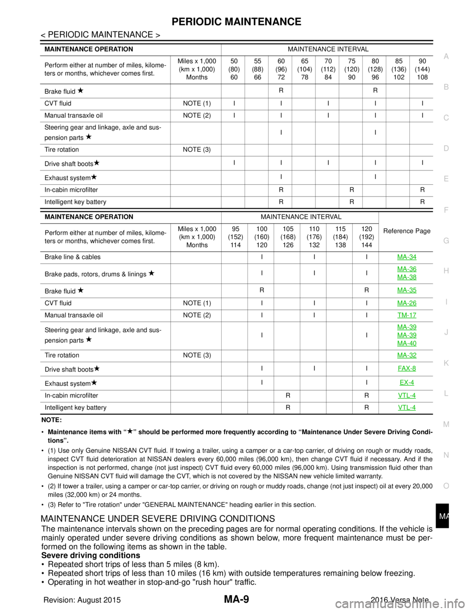
NOTE:
•
Maintenance items with “ ” shoul d be performed more frequently according to “Maintenance Under Severe Driving Condi-
tions”.
• (1) Use only Genuine NISSAN CVT fluid. If towing a trailer, using a camper or a car-top carrier, of driving on rough or muddy roads,
inspect CVT fluid deterioration at NISSAN dealers every 60,000 miles (96,000 km), then change CVT fluid if necessary. And if th e
inspection is not performed, change (not just inspect) CVT fluid every 60,000 miles (96,000 km). Using transmission fluid other than
Genuine NISSAN CVT fluid will damage the CVT, which is not covered by the NISSAN new vehicle limited warranty.
• (2) If tower a trailer, using a camper or car-top carrier, or driving on rough or muddy roads, change (not just inspect) oil a t every 20,000
miles (32,000 km) or 24 months.
• (3) Refer to "Tire rotation" under "GENERAL MAINTENANCE" heading earlier in this section.
MAINTENANCE UNDER SEVERE DRIVING CONDITIONS
The maintenance intervals shown on the preceding pages are for normal operating conditions. If the vehicle is
mainly operated under severe driving conditions as shown below, more frequent maintenance must be per-
formed on the following items as shown in the table.
Severe driving conditions
• Repeated short trips of less than 5 miles (8 km).
• Repeated short trips of less than 10 miles (16 km) wi th outside temperatures remaining below freezing.
• Operating in hot weather in stop-and-go "rush hour" traffic.
Brake fluid RR
C VT flu id NO TE (1)IIIII
M anu al t ra nsa xle o il NO TE (2)IIIII
Steering gear and linkage, axle and sus-
pension parts II
Tire rotation NOTE (3)
Drive shaft boots IIIII
Exhaust system II
In-cabin microfilter RRR
Intelligent key battery RRR
MAINTENANCE OPERATION MAINTENANCE INTERVAL
Reference Page
Perform either at number of miles, kilome-
ters or months, whichever comes first. Miles x 1,000
(km x 1,000) Months 95
(152) 11 4 100
(160) 120 105
(168) 126 11 0
(176) 132 11 5
(184) 138 120
(192) 144
Brake line & cables IIIMA-34
Brake pads, rotors, drums & linings IIIMA-36MA-38
Brake fluid
RR
MA-35
CVT fluid NOTE (1)IIIMA-26
Manual transaxle oil NOTE (2)IIITM-17
Steering gear and linkage, axle and sus-
pension parts IIMA-39MA-39
MA-40
Tire rotation
NOTE (3) MA-32
Drive shaft boots III
FAX-8
Exhaust system II
EX-4
In-cabin microfilter RRVTL-4
Intelligent key battery RRVTL-4
MAINTENANCE OPERATION MAINTENANCE INTERVAL
Perform either at number of miles, kilome-
ters or months, whichever comes first. Miles x 1,000
(km x 1,000)
Months 50
(80)
60 55
(88)
66 60
(96)
72 65
(104)
78 70
(112)
84 75
(120)
90 80
(128)
96 85
(136)
102 90
(144)
108
Revision: August 2015 2016 Versa Note
cardiagn.com
Page 2326 of 3641
RECOMMENDED FLUIDS AND LUBRICANTSMA-11
< PERIODIC MAINTENANCE >
C
DE
F
G H
I
J
K L
M B
MA
N
O A
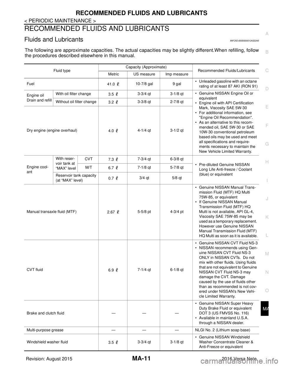
RECOMMENDED FLUIDS AND LUBRICANTS
Fluids and LubricantsINFOID:0000000012432245
The following are approximate capacities. The actual capa
cities may be slightly different.When refilling, follow
the procedures described elsewhere in this manual.
Fluid type Capacity (Approximate)
Recommended Fluids/Lubricants
Metric US measure Imp measure
Fuel 41.0 10-7/8 gal
9 gal• Unleaded gasoline with an octane
rating of at least 87 AKI (RON 91)
Engine oil
Drain and refill With oil filter change
3.5 3-3/4 qt 3-1/8 qt
• Genuine NISSAN Engine Oil or
equivalent
• Engine oil with API Certification
Mark, Viscosity SAE 5W-30
• For additional information, see "Engine Oil Recommendation".
• As an alternative to this recom-
mended oil, SAE 5W-30 or SAE
10W-30 conventional petroleum
based oils may be used and meet
all specifications and require-
ments necessary to maintain the
New Vehicle Limited Warranty.
Without oil filter change
3.2 3-3/8 qt 2-7/8 qt
Dry engine (engine overhaul) 4.0 4-1/4 qt 3-1/2 qt
Engine cool-
ant With reser-
voir tank at
“MAX” level
CVT
7.3 7-3/4 qt 6-3/8 qt
• Pre-diluted Genuine NISSAN Long Life Anti-freeze / Coolant
(blue) or equivalent
M/T
6.7 7-1/8 qt 5-7/8 qt
Reservoir tank capacity
(at “MAX” level) 0.7
3/4 qt
5/8 qt
Manual transaxle fluid (MTF) 2.67 5-5/8 pt 4-3/4 pt • Genuine NISSAN
Manual Trans-
mission Fluid (MTF) HQ Multi
75W-85, or equivalent
• If Genuine NISSAN Manual
Transmission Fluid (MTF) HQ
Multi is not available, API GL-4,
Viscosity SAE 75W-85 may be
used as a temporary replacement.
However use Genuine NISSAN
Manual Transmission Fluid (MTF)
HQ Multi as soon as it is available.
CVT fluid 6.9 7-1/4 qt 6-1/8 qt • Genuine NISSAN CVT Fluid NS-3
• NISSAN recommends using Gen-
uine NISSAN CVT Fluid NS-3
ONLY in NISSAN CVTs. Do not
mix with other fluids. Using fluids
that are not equivalent to Genuine
NISSAN CVT Fluid NS-3 may
damage the CVT. Damage
caused by the use of fluids other
than as recommended is not cov-
ered under NISSAN's New Vehi-
cle Limited Warranty.
Brake and clutch fluid —— —• Genuine NISSAN Super Heavy
Duty Brake Fluid or equivalent
DOT 3 (US FMVSS No. 116)
• Available in mainland U.S.A.
through a NISSAN dealer.
Multi-purpose grease —— — NLGI No. 2 (Lithium soap base)
Windshield washer fluid 3.5 3-3/4 qt 3-1/8 qt • Genuine NISSAN Windshield
Washer Concentrate Cleaner &
Anti-Freeze or equivalent
Revision: August 2015 2016 Versa Note
cardiagn.com
Page 2332 of 3641
ENGINE MAINTENANCEMA-17
< PERIODIC MAINTENANCE >
C
DE
F
G H
I
J
K L
M B
MA
N
O A
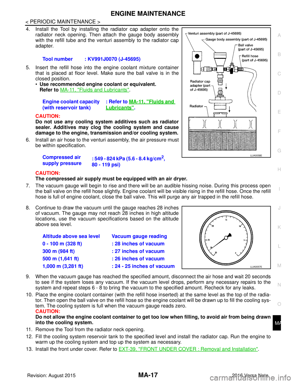
4. Install the Tool by installing the radiator cap adapter onto the
radiator neck opening. Then attach the gauge body assembly
with the refill tube and the venturi assembly to the radiator cap
adapter.
5. Insert the refill hose into the engine coolant mixture container that is placed at floor level. Make sure the ball valve is in the
closed position.
•Use recommended engine coolant or equivalent.
Refer to MA-11, "
Fluids and Lubricants".
CAUTION:
Do not use any cooling system additives such as radiator
sealer. Additives may clog the cooling system and cause
damage to the engine, transmission and/or cooling system.
6. Install an air hose to the venturi assembly, the air pressure must be within specification.
CAUTION:
The compressed air supply must be equipped with an air dryer.
7. The vacuum gauge will begin to rise and there will be an audible hissing noise. During this process open the ball valve on the refill hose slightly. Engine coolant will be visible rising in the refill hose. Once the refill
hose is full of engine coolant, close the ball valve. This will purge any air trapped in the refill hose.
8. Continue to draw the vacuum until the gauge reaches 28 inches of vacuum. The gauge may not reach 28 inches in high altitude
locations, use the vacuum specifications based on the altitude
above sea level.
9. When the vacuum gauge has reached the specified amount, disconnect the air hose and wait 20 seconds
to see if the system loses any vacuum. If the vacuum level drops, perform any necessary repairs to the
system and repeat steps 6 - 8 to br ing the vacuum to the specified amount. Recheck for any leaks.
10. Place the engine coolant container (with the refill hose in serted) at the same level as the top of the radia-
tor. Then open the ball valve on the refill hose so the engine coolant will be drawn up to fill the cooling sys-
tem. The cooling system is full when the vacuum gauge reads zero.
CAUTION:
Do not allow the engine coolant co ntainer to get too low when filling, to avoid air from being drawn
into the cooling system.
11. Remove the Tool from the radiator neck opening.
12. Fill the cooling system reservoir tank to the specif ied level and install the radiator cap. Run the engine to
warm up the cooling system and top up the system as necessary.
13. Install the front under cover. Refer to EXT-39, "
FRONT UNDER COVER : Removal and Installation".
Tool number : KV991J0070 (J-45695)
Engine coolant capacity
(with reservoir tank)
: Refer to
MA-11, "
Fluids and
Lubricants".
Compressed air
supply pressure : 549 - 824 kPa (5.6 - 8.4 kg/cm
2,
80 - 119 psi)LLIA0058E
Altitude above sea level Vacuum gauge reading
0 - 100 m (328 ft) : 28 inches of vacuum
300 m (984 ft) : 27 inches of vacuum
500 m (1,641 ft) : 26 inches of vacuum
1,000 m (3,281 ft) : 24 - 25 inches of vacuum
LLIA0057E
Revision: August 2015 2016 Versa Note
cardiagn.com
Page 2341 of 3641
MA-26
< PERIODIC MAINTENANCE >
CHASSIS AND BODY MAINTENANCE
CHASSIS AND BODY MAINTENANCE
EXHAUST SYSTEM
EXHAUST SYSTEM : InspectionINFOID:0000000012432266
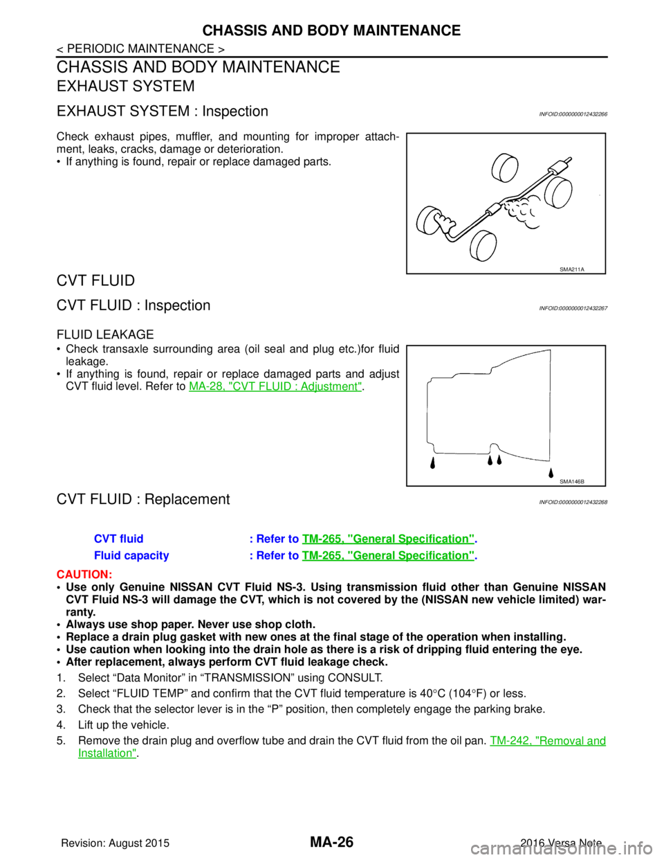
Check exhaust pipes, muffler, and mounting for improper attach-
ment, leaks, cracks, damage or deterioration.
• If anything is found, repair or replace damaged parts.
CVT FLUID
CVT FLUID : InspectionINFOID:0000000012432267
FLUID LEAKAGE
• Check transaxle surrounding area (oil seal and plug etc.)for fluidleakage.
• If anything is found, repair or replace damaged parts and adjust CVT fluid level. Refer to MA-28, "
CVT FLUID : Adjustment".
CVT FLUID : ReplacementINFOID:0000000012432268
CAUTION:
• Use only Genuine NISSAN CVT Fluid NS-3. Using transmission fluid other than Genuine NISSAN
CVT Fluid NS-3 will damage the CVT, which is not covered by the (NISSAN new vehicle limited) war-
ranty.
• Always use shop paper. Never use shop cloth.
• Replace a drain plug gasket with new ones at the final stage of the operation when installing.
• Use caution when looking into the drain hole as th ere is a risk of dripping fluid entering the eye.
• After replacement, always perform CVT fluid leakage check.
1. Select “Data Monitor” in “T RANSMISSION” using CONSULT.
2. Select “FLUID TEMP” and confirm t hat the CVT fluid temperature is 40°C (104° F) or less.
3. Check that the selector lever is in the “P ” position, then completely engage the parking brake.
4. Lift up the vehicle.
5. Remove the drain plug and overflow tube and drain the CVT fluid from the oil pan. TM-242, "
Removal and
Installation".
SMA211A
SMA146B
CVT fluid: Refer to TM-265, "General Specification".
Fluid capacity : Refer to TM-265, "
General Specification".
Revision: August 2015 2016 Versa Note
cardiagn.com
Page 2343 of 3641
MA-28
< PERIODIC MAINTENANCE >
CHASSIS AND BODY MAINTENANCE
29. When the flow of CVT fluid slows to a drip, tighten the drain plug to the specified torque. TM-242,
"Removal and Installation".
CAUTION:
Never reuse drain plug gasket.
30. Lift down the vehicle.
31. Select “Work Support” in “TRANSMISSION” using CONSULT.
32. Select “CONFORM CVTF DETERIORTN”.
33. Select “Erase”.
34. Stop the engine.
CVT FLUID : AdjustmentINFOID:0000000012432269
CAUTION:
• Use only Genuine NISSAN CVT Fluid NS-3. Using transmission fluid other than Genuine NISSAN
CVT Fluid NS-3 will damage the CVT, which is not covered by the (NISSAN new vehicle limited) war-
ranty.
• During adjustment of the CVT fluid level, check CO NSULT so that the oil temperature may be main-
tained from 35 to 45 °C (95 to 113 °F).
• Use caution when looking into the drain hole as th ere is a risk of dripping fluid entering the eye.
1. Check that the selector lever is in the “P ” position, then completely engage the parking brake.
2. Start the engine.
3. Adjust the CVT fluid temperature to be approximately 40 °C (104° F).
NOTE:
The CVT fluid is largely affected by temperature. Therefore be sure to use CONSULT and check the
“FLUID TEMP” under “TRANSMISSION” in “Data Monitor” while adjusting.
4. While depressing the brake pedal, shift the selector lever to the entire position from “P” to “L”, and shift it to the “P” position.
NOTE:
Hold the lever at each position for 5 seconds.
5. Lift up the vehicle.
6. Check that there is no CVT fluid leakage.
7. Remove the drain plug. Refer to TM-242, "
Removal and Installation".
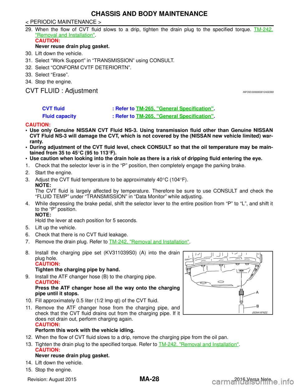
8. Install the charging pipe set (KV311039S0) (A) into the drain plug hole.
CAUTION:
Tighten the charging pipe by hand.
9. Install the ATF changer hose (B) to the charging pipe. CAUTION:
Press the ATF changer hose all the way onto the charging
pipe until it stops.
10. Fill approximately 0.5 liter (1/2 lmp qt) of the CVT fluid.
11. Remove the ATF changer hose from the charging pipe, and check that the CVT fluid drains out from the charging pipe. If it
does not drain out, perform charging again.
CAUTION:
Perform this work with the vehicle idling.
12. When the flow of CVT fluid slows to a drip, remove the charging pipe from the oil pan.
13. Tighten the drain plug to the specified torque. Refer to TM-242, "
Removal and Installation".
CAUTION:
Never reuse drain plug gasket.
14. Lift down the vehicle.
15. Stop the engine. CVT fluid
: Refer to TM-265, "
General Specification".
Fluid capacity : Refer to TM-265, "
General Specification".
JSDIA1876ZZ
Revision: August 2015 2016 Versa Note
cardiagn.com
Page 3243 of 3641

TM-2
INPUT SHAFT AND GEAR ...............................45
Exploded View ..................................................... ...45
Disassembly ...........................................................45
Assembly ................................................................45
Inspection ...............................................................45
MAINSHAFT AND GEAR ..................................47
Exploded View ..................................................... ...47
Disassembly ...........................................................47
Assembly ................................................................49
Inspection ...............................................................50
FINAL DRIVE .....................................................52
Exploded View ..................................................... ...52
Disassembly ...........................................................52
Assembly ................................................................52
Inspection ...............................................................52
SERVICE DATA AND SPECIFICATIONS
(SDS) ........................................................ ...
54
SERVICE DATA AND SPECIFICATIONS
(SDS) ............................................................... ...
54
General Specifications ......................................... ...54
CVT: RE0F11A
PRECAUTION .............. ...............................
55
PRECAUTIONS .............................................. ...55
Precaution for Supplemental Restraint System
(SRS) "AIR BAG" and "SEAT BELT PRE-TEN-
SIONER" .............................................................. ...
55
Precaution for Procedure without Cowl Top Cover ...55
Precaution for TCM, Transaxle Assembly or Con-
trol Valve Replacement ..........................................
55
Precaution for G Sensor Removal/Installation or
Replacement ..........................................................
55
General Precautions ...............................................56
On Board Diagnosis (OBD) System of CVT and
Engine ....................................................................
57
Removal and Installation Procedure for CVT Unit
Connector ...............................................................
57
PREPARATION ...........................................59
PREPARATION .............................................. ...59
Special Service Tools .......................................... ...59
Commercial Service Tools ......................................59
SYSTEM DESCRIPTION ............................61
COMPONENT PARTS .................................... ...61
CVT CONTROL SYSTEM ...................................... ...61
CVT CONTROL SYSTEM : Component Parts Lo-
cation ......................................................................
61
CVT CONTROL SYSTEM : TCM ...........................63
CVT CONTROL SYSTEM : ROM Assembly ....... ...63
CVT CONTROL SYSTEM : Transmission Range
Switch .................................................................. ...
63
CVT CONTROL SYSTEM : Primary Speed Sen-
sor ........................................................................ ...
63
CVT CONTROL SYSTEM : Secondary Speed
Sensor .....................................................................
63
CVT CONTROL SYSTEM : Output Speed Sensor ...64
CVT CONTROL SYSTEM : CVT Fluid Tempera-
ture Sensor .......................................................... ...
64
CVT CONTROL SYSTEM : Secondary Pressure
Sensor .................................................................. ...
65
CVT CONTROL SYSTEM : Primary Pressure So-
lenoid Valve ......................................................... ...
65
CVT CONTROL SYSTEM : Low Brake Solenoid
Valve .......................................................................
65
CVT CONTROL SYSTEM : High Clutch & Re-
verse Brake Solenoid Valve ....................................
66
CVT CONTROL SYSTEM : Torque Converter
Clutch Solenoid Valve .............................................
66
CVT CONTROL SYSTEM : Line Pressure Sole-
noid Valve ............................................................ ...
66
CVT CONTROL SYSTEM : G Sensor ....................66
CVT CONTROL SYSTEM : Overdrive Control
Switch .....................................................................
66
CVT CONTROL SYSTEM : O/D OFF Indicator
Lamp .......................................................................
66
CVT CONTROL SYSTEM : Shift Position Indica-
tor ............................................................................
68
CVT CONTROL SYSTEM : Malfunction Indicator
Lamp (MIL) ..............................................................
68
SHIFT LOCK SYSTEM ..............................................68
SHIFT LOCK SYSTEM : Co mponent Parts Loca-
tion ....................................................................... ...
68
STRUCTURE AND OPERATION ......................70
TRANSAXLE .......................................................... ...70
TRANSAXLE : Cross-Sectional View .....................70
TRANSAXLE : Transaxle Mechanism ... .................70
TRANSAXLE : Operation Stat us .............................72
TRANSAXLE : Oil Pressure System .......................73
TRANSAXLE : Component De scription ..................73
FLUID COOLER & FLUID WARMER SYSTEM ..... ...74
FLUID COOLER & FLUID WARMER SYSTEM :
System Description .................................................
74
SHIFT LOCK SYSTEM ..............................................74
SHIFT LOCK SYSTEM : Syst em Description .........75
KEY LOCK SYSTEM .............................................. ...75
KEY LOCK SYSTEM : System Description ............75
SYSTEM ......................................................... ...76
CVT CONTROL SYSTEM .........................................76
CVT CONTROL SYSTEM : System Description . ...76
CVT CONTROL SYSTEM : Fail-safe ......................78
CVT CONTROL SYSTEM : Protection Control .......80
LINE PRESSURE CONTROL ................................ ...81
LINE PRESSURE CONTROL : System Descrip-
tion ....................................................................... ...
82
Revision: August 2015 2016 Versa Note
cardiagn.com