Page 2174 of 3641
BODY SIDE TRIMINT-23
< REMOVAL AND INSTALLATION >
C
DE
F
G H
I
K L
M A
B
INT
N
O P
1. Release front kicking plate pawls and metal clip using a suitable tool (A) and remove front kicking plate as shown.
: Pawl
: Metal clip
Installation
Installation is in the reverse order of removal.
CAUTION:
• Visually check the clips and pawls for defo rmation and damage during installation.
• When installing front kicking plate, check that clips and pawls are securely placed into body panel holes.
REAR KICKING PLATE
Removal
1. Remove rear seat cushion. Refer to SE-41, "Seat Cushion".
2. Lift rear end of rear kicking plate to release metal clip, then rotate front end of rear kicking plate to release pawls and
remove.
: Pawl
: Metal clip
: Clip
Installation
Installation is in the reverse order of removal.
AWJIA1123ZZ
AWJIA1483ZZ
Revision: August 2015 2016 Versa Note
cardiagn.com
Page 2175 of 3641

INT-24
< REMOVAL AND INSTALLATION >
BODY SIDE TRIM
CAUTION:
• Visually check the clips and pawls for deformation and damage during installation.
• When installing rear kicking plate, check that clips and pawls ar e securely placed into body panel
holes.
DASH SIDE FINISHER
DASH SIDE FINISHER : Removal and InstallationINFOID:0000000012431867
REMOVAL
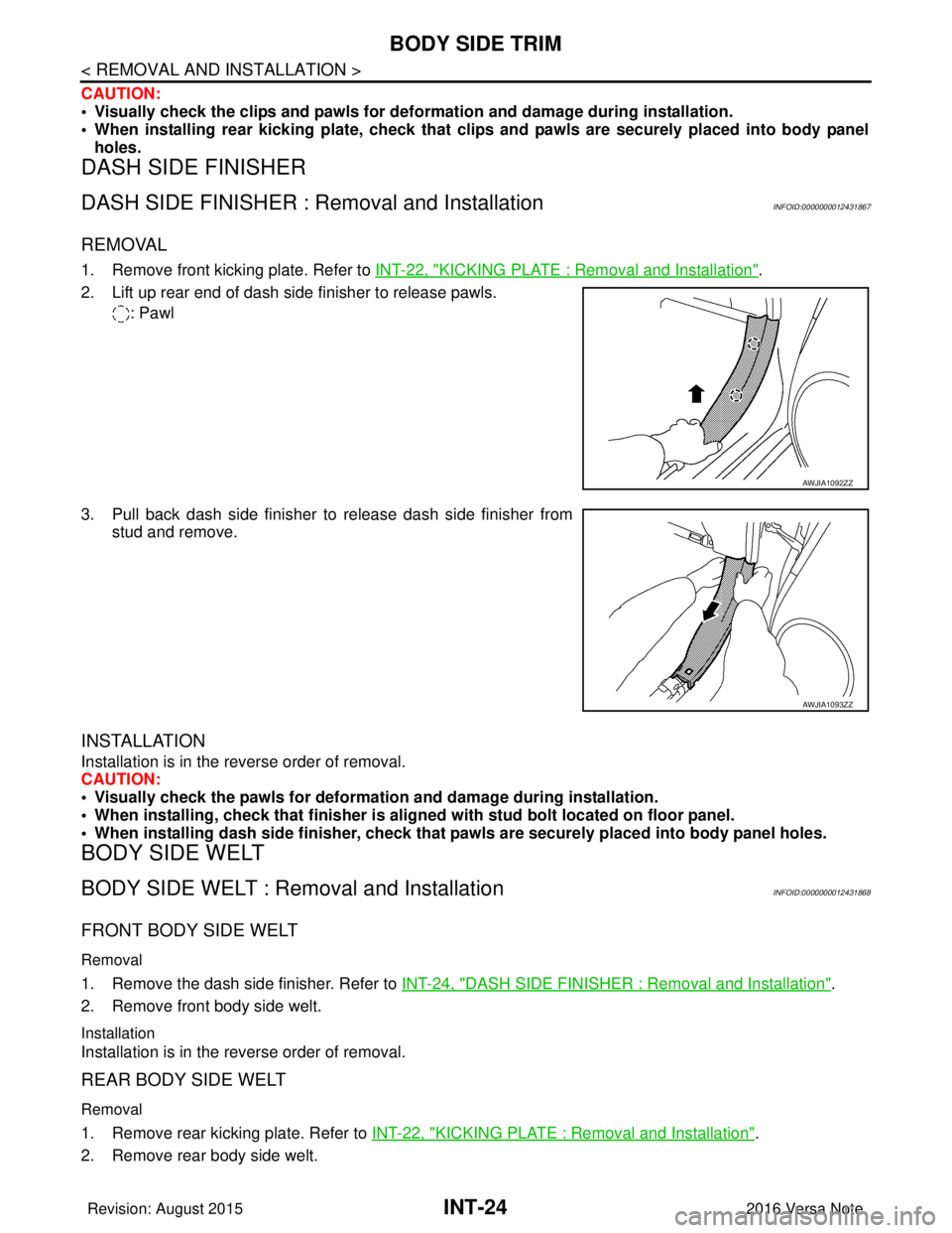
1. Remove front kicking plate. Refer to INT-22, "KICKING PLATE : Removal and Installation".
2. Lift up rear end of dash side finisher to release pawls. : Pawl
3. Pull back dash side finisher to release dash side finisher from stud and remove.
INSTALLATION
Installation is in the reverse order of removal.
CAUTION:
• Visually check the pawls for deformati on and damage during installation.
• When installing, check that fi nisher is aligned with stud bolt located on floor panel.
• When installing dash side fi nisher, check that pawls are secure ly placed into body panel holes.
BODY SIDE WELT
BODY SIDE WELT : Removal and InstallationINFOID:0000000012431868
FRONT BODY SIDE WELT
Removal
1. Remove the dash side finisher. Refer to INT-24, "DASH SIDE FINISHER : Removal and Installation".
2. Remove front body side welt.
Installation
Installation is in the reverse order of removal.
REAR BODY SIDE WELT
Removal
1. Remove rear kicking plate. Refer to INT-22, "KICKING PLATE : Removal and Installation".
2. Remove rear body side welt.
AWJIA1092ZZ
AWJIA1093ZZ
Revision: August 2015 2016 Versa Note
cardiagn.com
Page 2177 of 3641
INT-26
< REMOVAL AND INSTALLATION >
BODY SIDE TRIM
When releasing molded in clip, follow the steps as shown to prevent finisher or clip damage.
7. Release center pillar upper finisher lower clip using a suitable tool (A) and remove.
: Clip
CAUTION:
Do not reuse center pillar upper finisher.
INSTALLATION
Installation is in the reverse order of removal.
CAUTION:
• Do not reuse center pillar upper finisher. Replace with new part for installation.
• When installing center pillar upper finisher, check that clips are securely placed in body panel holes.
PIIB2600J
AWJIA1094ZZ
Revision: August 2015 2016 Versa Note
cardiagn.com
Page 2179 of 3641

INT-28
< REMOVAL AND INSTALLATION >
FLOOR TRIM
6. Disconnect negative and positive battery terminals, then wait at least three minutes. Refer to PG-70,
"Removal and Installation (Battery)".
WARNING:
Before servicing the SRS, turn th e ignition switch off, disconnect both battery terminals then wait
at least three minutes.
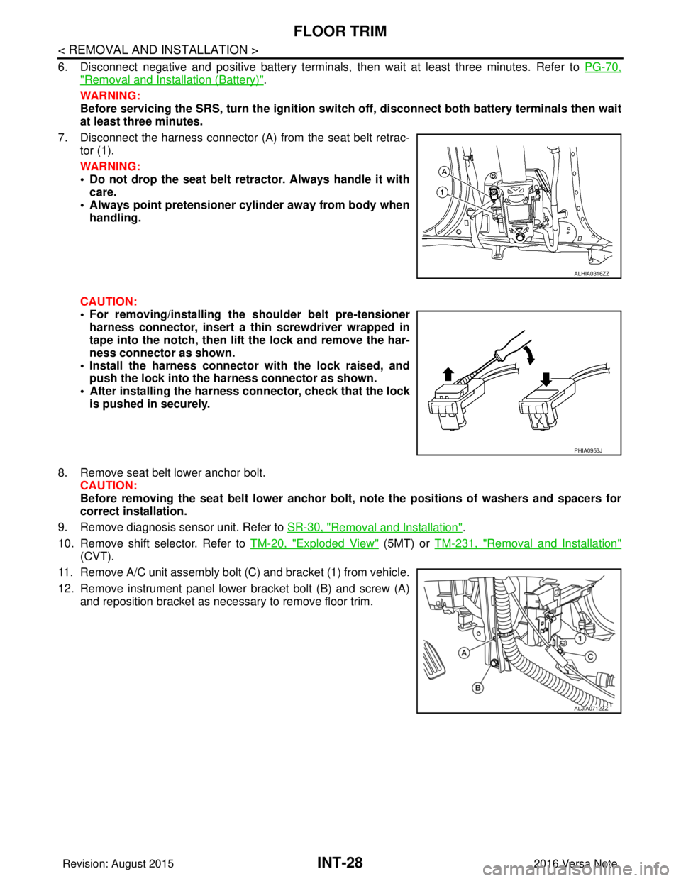
7. Disconnect the harness connector (A ) from the seat belt retrac-
tor (1).
WARNING:
• Do not drop the seat belt retractor. Always handle it with care.
• Always point pretensioner cylinder away from body when handling.
CAUTION:
• For removing/installing the shoulder belt pre-tensioner harness connector, insert a thin screwdriver wrapped in
tape into the notch, then lift the lock and remove the har-
ness connector as shown.
• Install the harness connector with the lock raised, and push the lock into the harness connector as shown.
• After installing the harness connector, check that the lock
is pushed in securely.
8. Remove seat belt lower anchor bolt. CAUTION:
Before removing the seat belt lower anchor bolt , note the positions of washers and spacers for
correct installation.
9. Remove diagnosis sensor unit. Refer to SR-30, "
Removal and Installation".
10. Remove shift selector. Refer to TM-20, "
Exploded View" (5MT) or TM-231, "Removal and Installation"
(CVT).
11. Remove A/C unit assembly bolt (C) and bracket (1) from vehicle.
12. Remove instrument panel lower bracket bolt (B) and screw (A) and reposition bracket as necessary to remove floor trim.
ALHIA0316ZZ
PHIA0953J
ALJIA0712ZZ
Revision: August 2015 2016 Versa Note
cardiagn.com
Page 2185 of 3641

IN T - 3 4
< REMOVAL AND INSTALLATION >
LUGGAGE TRIM
LUGGAGE REAR PLATE : Removal and Installation
INFOID:0000000012431876
REMOVAL
1. Remove luggage floor board (if equipped).
2. Remove luggage floor trim.
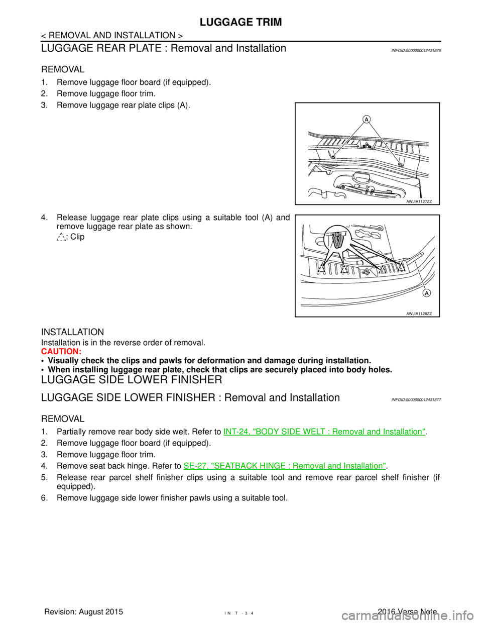
3. Remove luggage rear plate clips (A).
4. Release luggage rear plate clips using a suitable tool (A) and remove luggage rear plate as shown.
: Clip
INSTALLATION
Installation is in the reverse order of removal.
CAUTION:
• Visually check the clips and pawls for deformation and damage during installation.
• When installing luggage rear plate, check that clips are securely placed into body holes.
LUGGAGE SIDE LOWER FINISHER
LUGGAGE SIDE LOWER FINISHER : Removal and InstallationINFOID:0000000012431877
REMOVAL
1. Partially remove rear body side welt. Refer to INT-24, "BODY SIDE WELT : Removal and Installation".
2. Remove luggage floor board (if equipped).
3. Remove luggage floor trim.
4. Remove seat back hinge. Refer to SE-27, "
SEATBACK HINGE : Removal and Installation".
5. Release rear parcel shelf finisher clips using a su itable tool and remove rear parcel shelf finisher (if
equipped).
6. Remove luggage side lower finisher pawls using a suitable tool.
AWJIA1127ZZ
AWJIA1128ZZ
Revision: August 2015 2016 Versa Note
cardiagn.com
Page 2193 of 3641
LAN
HOW TO USE THIS SECTIONLAN-5
< HOW TO USE THIS MANUAL > [CAN FUNDAMENTAL]
C
D
E
F
G H
I
J
K L
B A
O P
N
HOW TO USE THIS MANUAL
HOW TO USE THIS SECTION
InformationINFOID:0000000012433327
• “CAN FUNDAMENTAL” of LAN Section describes t
he basic knowledge of the CAN communication system
and the method of trouble diagnosis.
• For information peculiar to a vehicle and inspection procedure, refer to “CAN”.
Revision: August 2015 2016 Versa Note
cardiagn.com
Page 2209 of 3641
LAN
HOW TO USE THIS SECTIONLAN-21
< HOW TO USE THIS MANUAL > [CAN]
C
D
E
F
G H
I
J
K L
B A
O P
N
HOW TO USE THIS MANUAL
HOW TO USE THIS SECTION
InformationINFOID:0000000012433340
• “CAN” of LAN Section describes information
peculiar to a vehicle and inspection procedures.
• For trouble diagnosis procedure, refer to LAN-16, "
Trouble Diagnosis Flow Chart" of “CAN FUNDAMEN-
TA L ” .
Abbreviation ListINFOID:0000000012433341
Unit name abbreviations in CONSULT CAN diagnosis and in this section are as per the following list.
Abbreviation Unit name
A-BAG Air bag diagnosis sensor unit
ABS ABS actuator and electric unit (control unit)
AV AV control unit
AVM Around view monitor control unit
BCM BCM
DLC Data link connector
ECM ECM
EPS EPS control unit
IPDM-E IPDM E/R
M&A Combination meter
STRG Steering angle sensor
TCM TCM
Revision: August 2015 2016 Versa Note
cardiagn.com
Page 2320 of 3641

GENERAL MAINTENANCEMA-5
< PERIODIC MAINTENANCE >
C
DE
F
G H
I
J
K L
M B
MA
N
O A
PERIODIC MAINTENANCE
GENERAL MAINTENANCE
Explanation of Gene
ral MaintenanceINFOID:0000000012432243
General maintenance includes those items which shoul d be checked during the normal day-to-day operation
of the vehicle. They are essential if the vehicle is to continue operati ng properly. The owners can perform the
checks and inspections themselves or they can have their NISSAN dealers do them.
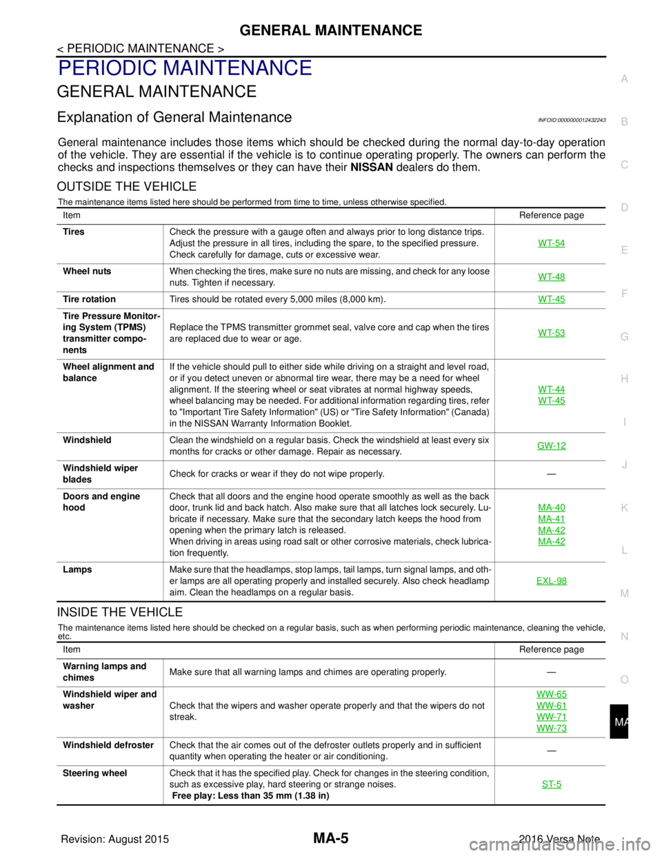
OUTSIDE THE VEHICLE
The maintenance items listed here should be performed from time to time, unless otherwise specified.
INSIDE THE VEHICLE
The maintenance items listed here should be checked on a regular basis, such as when performing periodic maintenance, cleaning the vehicle,
etc.
Item Reference page
Tires Check the pressure with a gauge often and always prior to long distance trips.
Adjust the pressure in all tires, including the spare, to the specified pressure.
Check carefully for damage, cuts or excessive wear. WT-54
Wheel nuts
When checking the tires, make sure no nuts are missing, and check for any loose
nuts. Tighten if necessary. WT-48
Tire rotation
Tires should be rotated every 5,000 miles (8,000 km). WT-45
Tire Pressure Monitor-
ing System (TPMS)
transmitter compo-
nentsReplace the TPMS transmitter grommet seal, valve core and cap when the tires
are replaced due to wear or age.
WT-53
Wheel alignment and
balanceIf the vehicle should pull to either side while driving on a straight and level road,
or if you detect uneven or abnormal tire wear, there may be a need for wheel
alignment. If the steering wheel or seat vibrates at normal highway speeds,
wheel balancing may be needed. For additional information regarding tires, refer
to "Important Tire Safety Information" (US) or "Tire Safety Information" (Canada)
in the NISSAN Warranty
Information Booklet. WT-44
WT-45
Windshield
Clean the windshield on a regular basis. Check the windshield at least every six
months for cracks or other damage. Repair as necessary. GW-12
Windshield wiper
bladesCheck for cracks or wear if they do not wipe properly.
—
Doors and engine
hood Check that all doors and the engine hood operate smoothly as well as the back
door, trunk lid and back hatch. Also make sure that all latches lock securely. Lu-
bricate if necessary. Make sure that the secondary latch keeps the hood from
opening when the primary latch is released.
When driving in areas using road salt or other corrosive materials, check lubrica-
tion frequently. MA-40
MA-41
MA-42
MA-42
Lamps
Make sure that the headlamps, stop lamps, tail lamps, turn signal lamps, and oth-
er lamps are all operating properly and installed securely. Also check headlamp
aim. Clean the headlamps on a regular basis. EXL-98
Item
Reference page
Warning lamps and
chimes Make sure that all warning lamps and chimes are operating properly.
—
Windshield wiper and
washer Check that the wipers and washer operate properly and that the wipers do not
streak. WW-65
WW-61
WW-71
WW-73
Windshield defroster
Check that the air comes out of the defroster outlets properly and in sufficient
quantity when operating the heater or air conditioning. —
Steering wheel Check that it has the specified play. Check for changes in the steering condition,
such as excessive play, hard steering or strange noises.
Free play: Less than 35 mm (1.38 in) ST-5
Revision: August 2015
2016 Versa Note
cardiagn.com