2016 NISSAN NOTE ECU
[x] Cancel search: ECUPage 2321 of 3641
MA-6
< PERIODIC MAINTENANCE >
GENERAL MAINTENANCE
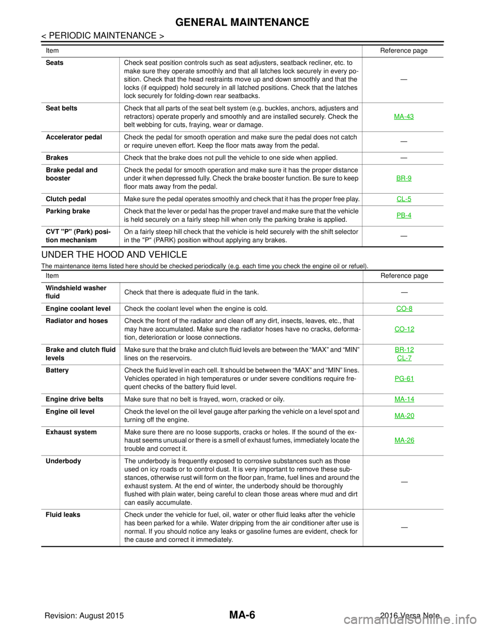
UNDER THE HOOD AND VEHICLE
The maintenance items listed here should be checked periodically (e.g. each time you check the engine oil or refuel).
SeatsCheck seat position controls such as seat adjusters, seatback recliner, etc. to
make sure they operate smoothly and that all latches lock securely in every po-
sition. Check that the head restraints move up and down smoothly and that the
locks (if equipped) hold securely in all latched positions. Check that the latches
lock securely for folding-down rear seatbacks. —
Seat belts Check that all parts of the seat belt system (e.g. buckles, anchors, adjusters and
retractors) operate properly and smoothly and are installed securely. Check the
belt webbing for cuts, fraying, wear or damage. MA-43
Accelerator pedal
Check the pedal for smooth operation and make sure the pedal does not catch
or require uneven effort. Keep the floor mats away from the pedal. —
Brakes Check that the brake does not pull the vehicle to one side when applied. —
Brake pedal and
booster Check the pedal for smooth operation and make sure it has the proper distance
under it when depressed fully. Check the brake booster function. Be sure to keep
floor mats away from the pedal. BR-9
Clutch pedal
Make sure the pedal operates smoothly and check that it has the proper free play. CL-5
Parking brakeCheck that the lever or pedal has the proper travel and make sure that the vehicle
is held securely on a fairly steep hill when only the parking brake is applied. PB-4
CVT "P" (Park) posi-
tion mechanismOn a fairly steep hill check that the vehicle is held securely with the shift selector
in the "P" (PARK) position without applying any brakes.
—
Item
Reference page
Item Reference page
Windshield washer
fluid Check that there is adequate fluid in the tank.
—
Engine coolant level Check the coolant level when the engine is cold. CO-8
Radiator and hosesCheck the front of the radiator and clean off any dirt, insects, leaves, etc., that
may have accumulated. Make sure the radiator hoses have no cracks, deforma-
tion, deterioration or loose connections. CO-12
Brake and clutch fluid
levelsMake sure that the brake and clutch fluid levels are between the “MAX” and “MIN”
lines on the reservoirs. BR-12
CL-7
Battery
Check the fluid level in each cell. It should be between the “MAX” and “MIN” lines.
Vehicles operated in high temperatures or under severe conditions require fre-
quent checks of the battery fluid level. PG-61
Engine drive belts
Make sure that no belt is frayed, worn, cracked or oily. MA-14
Engine oil levelCheck the level on the oil level gauge after parking the vehicle on a level spot and
turning off the engine. MA-20
Exhaust system
Make sure there are no loose supports, cracks or holes. If the sound of the ex-
haust seems unusual or there is a smell of exhaust fumes, immediately locate the
trouble and correct it. MA-26
Underbody
The underbody is frequently exposed to corrosive substances such as those
used on icy roads or to control dust. It is very important to remove these sub-
stances, otherwise rust will form on the floor pan, frame, fuel lines and around the
exhaust system. At the end of winter, the underbody should be thoroughly
flushed with plain water, being careful to clean those areas where mud and dirt
can easily accumulate. —
Fluid leaks Check under the vehicle for fuel, oil, water or other fluid leaks after the vehicle
has been parked for a while. Water dripping from the air conditioner after use is
normal. If you should notice any leaks or gasoline fumes are evident, check for
the cause and correct it immediately. —
Revision: August 2015
2016 Versa Note
cardiagn.com
Page 2328 of 3641
ENGINE MAINTENANCEMA-13
< PERIODIC MAINTENANCE >
C
DE
F
G H
I
J
K L
M B
MA
N
O A
ENGINE MAINTENANCE
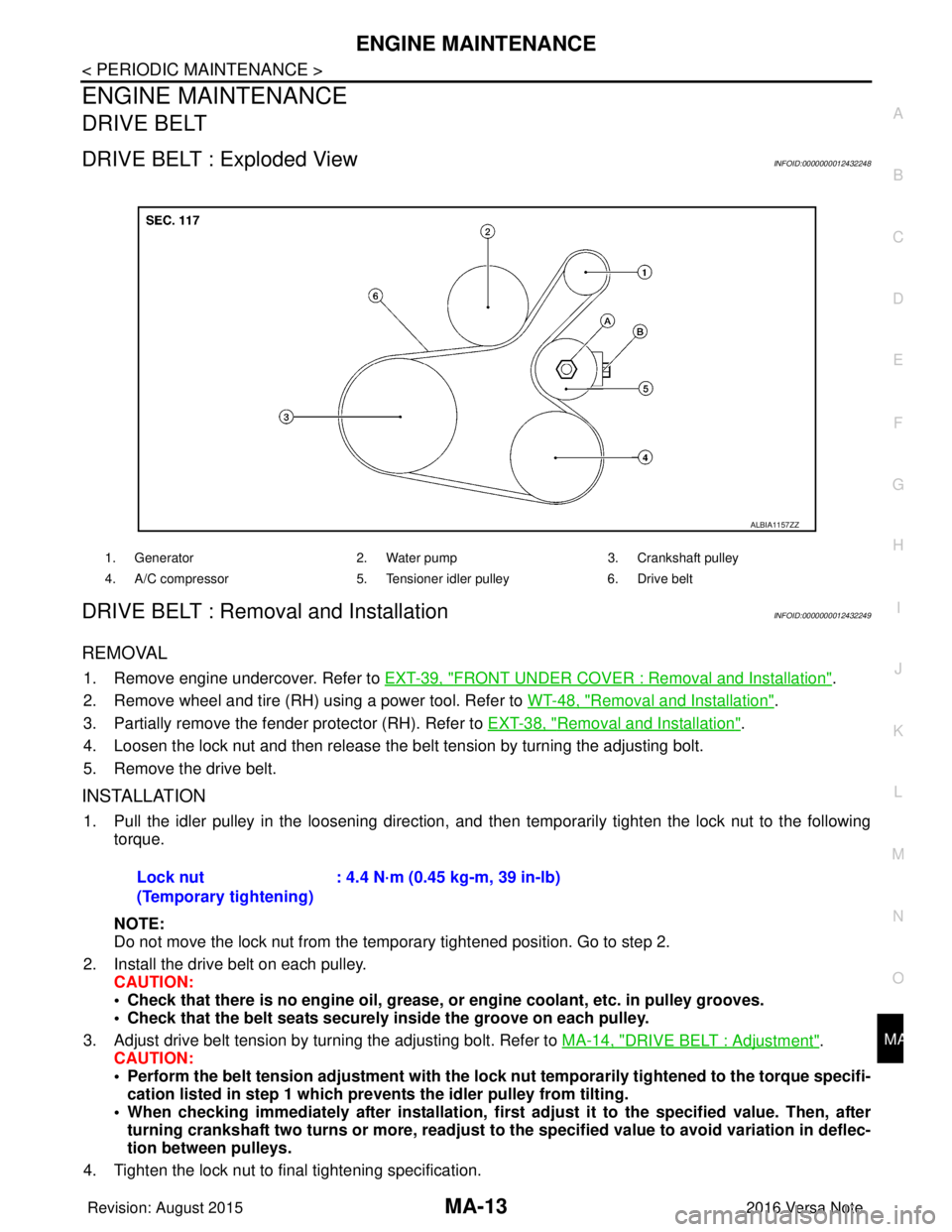
DRIVE BELT
DRIVE BELT : Exploded ViewINFOID:0000000012432248
DRIVE BELT : Removal and InstallationINFOID:0000000012432249
REMOVAL
1. Remove engine undercover. Refer to
EXT-39, "FRONT UNDER COVER : Removal and Installation".
2. Remove wheel and tire (RH) using a power tool. Refer to WT-48, "
Removal and Installation".
3. Partially remove the fender protector (RH). Refer to EXT-38, "
Removal and Installation".
4. Loosen the lock nut and then release the belt tension by turning the adjusting bolt.
5. Remove the drive belt.
INSTALLATION
1. Pull the idler pulley in the loosening direction, and then temporarily tighten the lock nut to the following
torque.
NOTE:
Do not move the lock nut from the temporary tightened position. Go to step 2.
2. Install the drive belt on each pulley. CAUTION:
• Check that there is no engine oil, grease, or engine coolant, etc. in pulley grooves.
• Check that the belt seats securely inside the groove on each pulley.
3. Adjust drive belt tension by turning the adjusting bolt. Refer to MA-14, "
DRIVE BELT : Adjustment".
CAUTION:
• Perform the belt tension adjustment with the lock nut temporarily tightened to the torque specifi-
cation listed in step 1 which preven ts the idler pulley from tilting.
• When checking immediately after in stallation, first adjust it to the specified value. Then, after
turning crankshaft two turns or more, readjust to the specified value to avoid variation in deflec-
tion between pulleys.
4. Tighten the lock nut to final tightening specification.
1. Generator 2. Water pump3. Crankshaft pulley
4. A/C compressor 5. Tensioner idler pulley6. Drive belt
ALBIA1157ZZ
Lock nut
(Temporary tightening): 4.4 N·m (0.45 kg-m, 39 in-lb)
Revision: August 2015
2016 Versa Note
cardiagn.com
Page 2335 of 3641
MA-20
< PERIODIC MAINTENANCE >
ENGINE MAINTENANCE
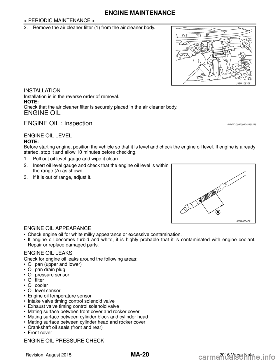
2. Remove the air cleaner filter (1) from the air cleaner body.
INSTALLATION
Installation is in the reverse order of removal.
NOTE:
Check that the air cleaner filter is securely placed in the air cleaner body.
ENGINE OIL
ENGINE OIL : InspectionINFOID:0000000012432259
ENGINE OIL LEVEL
NOTE:
Before starting engine, position the vehicle so that it is level and check the engine oil level. If engine is already
started, stop it and allow 10 minutes before checking.
1. Pull out oil level gauge and wipe it clean.
2. Insert oil level gauge and check that the engine oil level is withinthe range (A) as shown.
3. If it is out of range, adjust it.
ENGINE OIL APPEARANCE
• Check engine oil for white milky appearance or excessive contamination.
• If engine oil becomes turbid and white, it is highl y probable that it is contaminated with engine coolant.
Repair or replace damaged parts.
ENGINE OIL LEAKS
Check for engine oil leaks around the following areas:
• Oil pan (upper and lower)
• Oil pan drain plug
• Oil pressure sensor
• Oil filter
• Oil cooler
• Oil level sensor
• Engine oil temperature sensor
• Intake valve timing control solenoid valve
• Exhaust valve timing control solenoid valve
• Mating surface between front cover and rocker cover
• Mating surface between cylinder block and cylinder head
• Mating surface between cylinder head and rocker cover
• Crankshaft oil seals (front and rear)
• Front cover
ENGINE OIL PRESSURE CHECK
JSBIA1093ZZ
JPBIA0554ZZ
Revision: August 2015 2016 Versa Note
cardiagn.com
Page 2336 of 3641
ENGINE MAINTENANCEMA-21
< PERIODIC MAINTENANCE >
C
DE
F
G H
I
J
K L
M B
MA
N
O A
WARNING:
• Be careful not to burn yoursel
f, as engine oil may be hot.
• When checking engine oil pressure, sh ift selector should be in the "P" (Park) or "N" (Neutral) posi-
tion, and apply parking brake securely.
1. Check engine oil level.
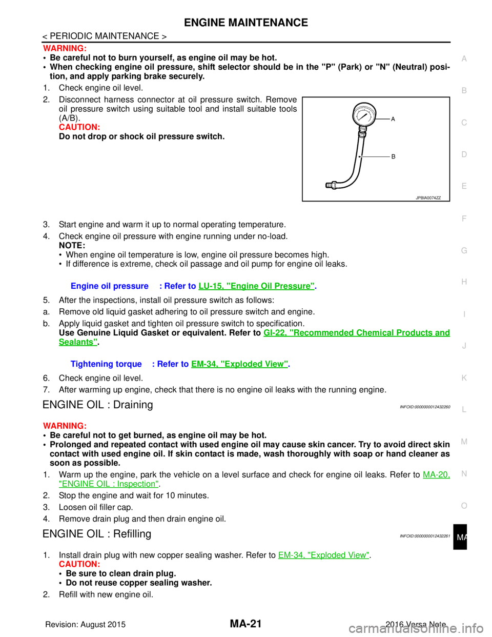
2. Disconnect harness connector at oil pressure switch. Remove oil pressure switch using suitable tool and install suitable tools
(A/B).
CAUTION:
Do not drop or shock oil pressure switch.
3. Start engine and warm it up to normal operating temperature.
4. Check engine oil pressure with engine running under no-load. NOTE:
• When engine oil temperature is low, engine oil pressure becomes high.
• If difference is extreme, check oil passage and oil pump for engine oil leaks.
5. After the inspections, install oil pressure switch as follows:
a. Remove old liquid gasket adhering to oil pressure switch and engine.
b. Apply liquid gasket and tighten oil pressure switch to specification. Use Genuine Liquid Gasket or equivalent. Refer to GI-22, "
Recommended Chemical Products and
Sealants".
6. Check engine oil level.
7. After warming up engine, check that there is no engine oil leaks with the running engine.
ENGINE OIL : DrainingINFOID:0000000012432260
WARNING:
• Be careful not to get burned, as engine oil may be hot.
• Prolonged and repeated contact with used engine oil may cause skin cancer. Try to avoid direct skin
contact with used engine oil. If skin contact is made, wash thorough ly with soap or hand cleaner as
soon as possible.
1. Warm up the engine, park the vehicle on a level surface and check for engine oil leaks. Refer to MA-20,
"ENGINE OIL : Inspection".
2. Stop the engine and wait for 10 minutes.
3. Loosen oil filler cap.
4. Remove drain plug and then drain engine oil.
ENGINE OIL : RefillingINFOID:0000000012432261
1. Install drain plug with new copper sealing washer. Refer to EM-34, "Exploded View".
CAUTION:
• Be sure to clean drain plug.
• Do not reuse copper sealing washer.
2. Refill with new engine oil.
JPBIA0074ZZ
Engine oil pressure : Refer to LU-15, "Engine Oil Pressure".
Tightening torque : Refer to EM-34, "
Exploded View".
Revision: August 2015 2016 Versa Note
cardiagn.com
Page 2352 of 3641
CHASSIS AND BODY MAINTENANCEMA-37
< PERIODIC MAINTENANCE >
C
DE
F
G H
I
J
K L
M B
MA
N
O A
DISC BRAKE : Brake BurnishingINFOID:0000000012432285
BRAKE BURNISHING
Burnish contact surfaces between disc brake rotor and brake pads according to the following procedure after
refinishing disc brake rotors, replacing disc brake rotors,
replacing brake pads, or if a soft pedal occurs at very
low mileage:
CAUTION:
• Be careful of vehicle speed because the brake peda l does not operate firmly/securely until pads and
disc brake rotor are securely seated.
• Only perform this procedure under safe road and traffic conditions. Use extreme caution.
1. Drive vehicle on straight, flat road.
2. Depress brake pedal with the power to stop vehicle within 3 to 5 seconds until the vehicle stops.
3. Drive without depressing brake pedal for a few minutes to cool the brakes.
4. Repeat steps 1 to 3 until pad and disc brake rotor are securely seated.
DISC BRAKE : InspectionINFOID:0000000012432286
INSPECTION
Appearance
Check surface of disc brake rotor for uneven wear, cra cks, and serious damage. Replace it if necessary. Refer
to BR-45, "
Front Disc Brake".
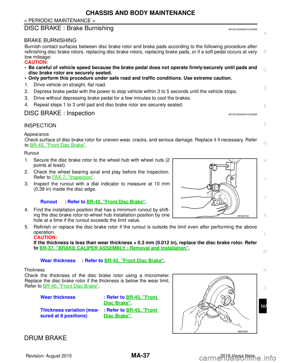
Runout
1. Secure the disc brake rotor to the wheel hub with wheel nuts (2
points at least).
2. Check the wheel bearing axial end play before the inspection. Refer to FA X - 7 , "
Inspection".
3. Inspect the runout with a dial indicator to measure at 10 mm (0.39 in) inside the disc edge.
4. Find the installation position that has a minimum runout by shift-
ing the disc brake rotor-to-wheel hub installation position by one
hole at a time if the runout exceeds the limit value.
5. Refinish or replace the disc brake rotor if the runout is outside the limit even after performing the above
operation.
CAUTION:
If the thickness is less than w ear thickness + 0.3 mm (0.012 in), replace the disc brake rotor. Refer
to BR-37, "
BRAKE CALIPER ASSEMBLY : Removal and Installation".
Thickness
Check the thickness of the disc brake rotor using a micrometer.
Replace the disc brake rotor if the thickness is below the wear limit.
Refer to BR-45, "
Front Disc Brake".
DRUM BRAKE
Runout : Refer to BR-45, "Front Disc Brake".
Wear thickness : Refer to BR-45, "
Front Disc Brake".
BRA0013D
Wear thickness: Refer to BR-45, "Front
Disc Brake".
Thickness variation (mea-
sured at 8 positions) : Refer to
BR-45, "
Front
Disc Brake".
SBR020B
Revision: August 2015 2016 Versa Note
cardiagn.com
Page 2353 of 3641
MA-38
< PERIODIC MAINTENANCE >
CHASSIS AND BODY MAINTENANCE
DRUM BRAKE : Inspection
INFOID:0000000012432287
INSPECTION
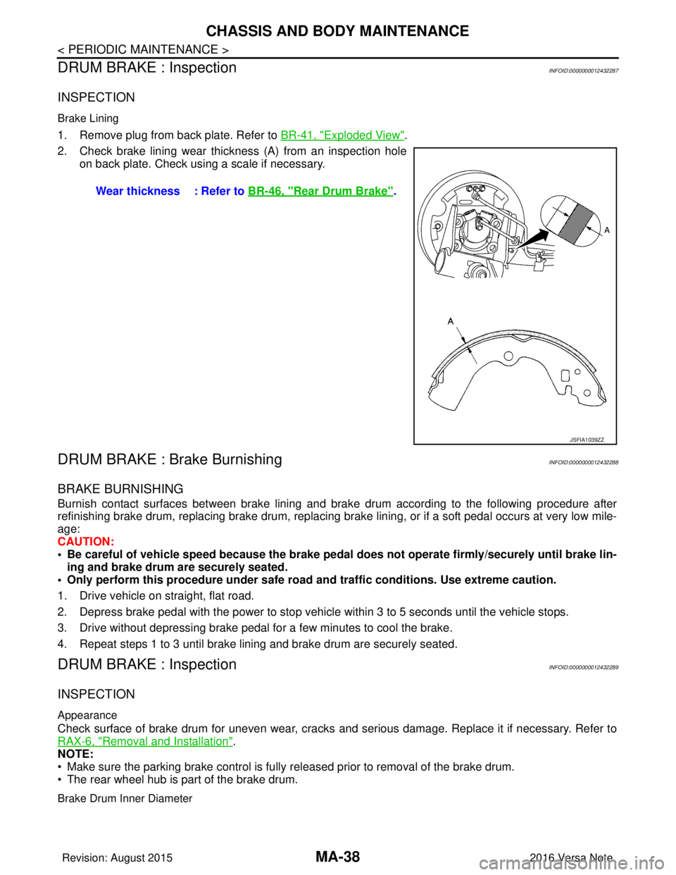
Brake Lining
1. Remove plug from back plate. Refer to BR-41, "Exploded View".
2. Check brake lining wear thickness (A) from an inspection hole on back plate. Check using a scale if necessary.
DRUM BRAKE : Brake BurnishingINFOID:0000000012432288
BRAKE BURNISHING
Burnish contact surfaces between brake lining and brak e drum according to the following procedure after
refinishing brake drum, replacing brake drum, replacing brak e lining, or if a soft pedal occurs at very low mile-
age:
CAUTION:
• Be careful of vehicle speed because the brake peda l does not operate firmly/securely until brake lin-
ing and brake drum are securely seated.
• Only perform this procedure under safe road and traffic conditions. Use extreme caution.
1. Drive vehicle on straight, flat road.
2. Depress brake pedal with the power to stop vehicle within 3 to 5 seconds until the vehicle stops.
3. Drive without depressing brake pedal for a few minutes to cool the brake.
4. Repeat steps 1 to 3 until brake lining and brake drum are securely seated.
DRUM BRAKE : InspectionINFOID:0000000012432289
INSPECTION
Appearance
Check surface of brake drum for uneven wear, cracks and serious damage. Replace it if necessary. Refer to
RAX-6, "
Removal and Installation".
NOTE:
• Make sure the parking brake control is fully released prior to removal of the brake drum.
• The rear wheel hub is part of the brake drum.
Brake Drum Inner Diameter
Wear thickness : Refer to BR-46, "Rear Drum Brake".
JSFIA1039ZZ
Revision: August 2015 2016 Versa Note
cardiagn.com
Page 2359 of 3641

MWI
MWI-1
DRIVER INFORMATION & MULTIMEDIA
C
DE
F
G H
I
J
K L
M B
SECTION MWI
A
O P
CONTENTS
METER, WARNING LAMP & INDICATOR
TYPE A
HOW TO USE THIS MANU AL ......................
5
APPLICATION NOTICE ................................. .....5
Information .......................................................... ......5
PRECAUTION ...............................................6
PRECAUTIONS .............................................. .....6
Precaution for Supplemental Restraint System
(SRS) "AIR BAG" and "SEAT BELT PRE-TEN-
SIONER" ............................................................. ......
6
PREPARATION ............................................7
PREPARATION .............................................. .....7
Commercial Service Tools .................................. ......7
SYSTEM DESCRIPTION ..............................8
COMPONENT PARTS ................................... .....8
METER SYSTEM .........................................................8
METER SYSTEM : Compo nent Parts Location ........8
METER SYSTEM : Combinat ion Meter ....................9
SYSTEM ......................................................... ....10
METER SYSTEM .......................................................10
METER SYSTEM : System Description ..................10
METER SYSTEM : Fail-safe ...................................11
SPEEDOMETER ................ ........................................12
SPEEDOMETER : System Description ............... ....12
TACHOMETER ...................................................... ....12
TACHOMETER : System Description .....................12
SHIFT POSITION INDICATOR .............................. ....12
SHIFT POSITION INDICATOR : System Descrip-
tion ...................................................................... ....
13
OIL PRESSURE WARNING LAMP ...........................13
OIL PRESSURE WARNING LAMP : System De-
scription ............................................................... ....
13
METER ILLUMINATION CONTROL ..................... ....13
METER ILLUMINATION CONTROL : System De-
scription ...................................................................
13
INFORMATION DISPLAY ...................................... ....14
INFORMATION DISPLAY : System Description .....14
OPERATION .....................................................16
Switch Name and Function ......................................16
DIAGNOSIS SYSTEM (COMBINATION
METER) .............................................................
17
On Board Diagnosis Function ..................................17
CONSULT Function (METER/M&A) ........................18
ECU DIAGNOSIS INFORMATION ..............21
COMBINATION METER ...................................21
Reference Value .................................................. ....21
Fail-safe ...................................................................23
DTC Index ...............................................................24
BCM (BODY CONTROL MODULE) .................25
List of ECU Reference .............................................25
WIRING DIAGRAM ......................................26
METER SYSTEM ..............................................26
Wiring Diagram .................................................... ....26
BASIC INSPECTION ...................................37
DIAGNOSIS AND REPAIR WORK FLOW .......37
Work Flow ............................................................ ....37
DTC/CIRCUIT DIAGNOSIS .........................38
U1000 CAN COMM CIRCUIT ...........................38
DTC Logic ............................................................ ....38
Diagnosis Procedure ..............................................38
Revision: August 2015 2016 Versa Note
cardiagn.com
Page 2361 of 3641

MWI
MWI-3
C
DE
F
G H
I
J
K L
M B
A
O P
OIL PRESSURE WARNING
LAMP ...........................
65
OIL PRESSURE WARNING LAMP : System De-
scription ............................................................... ....
65
METER ILLUMINATION CONTROL ..................... ....65
METER ILLUMINATION CONTROL : System De-
scription ...................................................................
66
INFORMATION DISPLAY ..................................... ....66
INFORMATION DISPLAY : System Description .....66
OPERATION ................................................... ....68
Switch Name and Function ................................. ....68
DIAGNOSIS SYSTEM (COMBINATION
METER) ..............................................................
69
On Board Diagnosis Function ............................. ....69
CONSULT Function (METER/M&A) .......................71
ECU DIAGNOSIS INFORMATION ..............74
COMBINATION METER ................................. ....74
Reference Value ................................................. ....74
Fail-safe ..................................................................77
DTC Index ...............................................................77
BCM (BODY CONTROL MODULE) ...................78
List of ECU Reference ........................................ ....78
WIRING DIAGRAM ......................................79
METER SYSTEM ............................................ ....79
Wiring Diagram ................................................... ....79
BASIC INSPECTION ...................................92
DIAGNOSIS AND REPAIR WORK FLOW .... ....92
Work Flow ........................................................... ....92
DTC/CIRCUIT DIAGNOSIS .........................93
U1000 CAN COMM CI RCUIT .............................93
DTC Logic ........................................................... ....93
Diagnosis Procedure ..............................................93
U1010 CONTROL UNIT (CAN) ..........................94
Description ..............................................................94
DTC Logic ...............................................................94
Diagnosis Procedure ...............................................94
B2205 VEHICLE SPEED ....................................95
Description ..............................................................95
DTC Logic ...............................................................95
Diagnosis Procedure ..............................................95
B2267 ENGINE SPEED .....................................96
Description .......................................................... ....96
DTC Logic ...............................................................96
Diagnosis Procedure ...............................................96
B2268 WATER TEMP ........................................97
Description .......................................................... ....97
DTC Logic ...............................................................97
Diagnosis Procedure ........................................... ....97
POWER SUPPLY AND GROUND CIRCUIT ....98
COMBINATION METER ........................................ ....98
COMBINATION METER : Diagnosis Procedure .....98
BCM (BODY CONTROL SYSTEM) (WITHOUT IN-
TELLIGENT KEY SYSTEM) .................................. ....
98
BCM (BODY CONTROL SYSTEM) (WITHOUT
INTELLIGENT KEY SYSTEM) : Diagnosis Proce-
dure ..................................................................... ....
98
BCM (BODY CONTROL SYSTEM) (WITH INTEL-
LIGENT KEY SYSTEM) .............................................
99
BCM (BODY CONTROL SYSTEM) (WITH INTEL-
LIGENT KEY SYSTEM) : Diagnosis Procedure .. ....
99
FUEL LEVEL SENSOR SIGNAL CIRCUIT ....101
Description .............................................................101
Component Function Check ..................................101
Diagnosis Procedure ............................................101
Component Inspection ...........................................102
STEERING SWITCH .......................................103
Diagnosis Procedure .............................................103
AMBIENT SENSOR SIGNAL CIRCUIT ..........104
Description .............................................................104
Diagnosis Procedure ............................................104
Component Inspection ...........................................105
WASHER FLUID LEVEL SWITCH CIRCUIT ..106
Description .............................................................106
Diagnosis Procedure .............................................106
Component Inspection ...........................................106
SYMPTOM DIAGNOSIS ............................107
THE FUEL GAUGE INDICATOR DOES NOT
OPERATE .......................................................
107
Description ........................................................... ..107
Diagnosis Procedure .............................................107
THE OIL PRESSURE WARNING LAMP
DOES NOT TURN ON .....................................
108
Description .............................................................108
Diagnosis Procedure .............................................108
THE OIL PRESSURE WARNING LAMP
DOES NOT TURN OFF ...................................
109
Description .............................................................109
Diagnosis Procedure .............................................109
THE DOOR OPEN WARNING CONTINUES
DISPLAYING, OR DOES NOT DISPLAY .......
110
Description .............................................................110
Diagnosis Procedure .............................................110
THE PARKING BRAKE RELEASE WARNING
CONTINUES DISPLAYING, OR DOES NOT
DISPLAY .........................................................
111
Revision: August 2015 2016 Versa Note
cardiagn.com