2016 NISSAN NOTE air filter
[x] Cancel search: air filterPage 1637 of 3641
![NISSAN NOTE 2016 Service Repair Manual ENGINE OILLU-7
< PERIODIC MAINTENANCE > [HR16DE]
C
D
E
F
G H
I
J
K L
M A
LU
NP
O
PERIODIC MAINTENANCE
ENGINE OIL
InspectionINFOID:0000000012432200
ENGINE OIL LEVEL
NOTE:
Before starting engine, positi NISSAN NOTE 2016 Service Repair Manual ENGINE OILLU-7
< PERIODIC MAINTENANCE > [HR16DE]
C
D
E
F
G H
I
J
K L
M A
LU
NP
O
PERIODIC MAINTENANCE
ENGINE OIL
InspectionINFOID:0000000012432200
ENGINE OIL LEVEL
NOTE:
Before starting engine, positi](/manual-img/5/57363/w960_57363-1636.png)
ENGINE OILLU-7
< PERIODIC MAINTENANCE > [HR16DE]
C
D
E
F
G H
I
J
K L
M A
LU
NP
O
PERIODIC MAINTENANCE
ENGINE OIL
InspectionINFOID:0000000012432200
ENGINE OIL LEVEL
NOTE:
Before starting engine, position the vehicle so that it
is level and check the engine oil level. If engine is already
started, stop it and allow 10 minutes before checking.
1. Pull out oil level gauge and wipe it clean.
2. Insert oil level gauge and check that the engine oil level is within the range (A) as shown.
3. If it is out of range, adjust it.
ENGINE OIL APPEARANCE
• Check engine oil for white milky appearance or excessive contamination.
• If engine oil becomes turbid and white, it is highly probable that it is contaminated with engine coolant. Repair or replace damaged parts.
ENGINE OIL LEAKS
Check for engine oil leaks around the following areas:
• Oil pan (upper and lower)
• Oil pan drain plug
• Oil pressure sensor
• Oil filter
• Oil cooler
• Oil level sensor
• Engine oil temperature sensor
• Intake valve timing control solenoid valve
• Exhaust valve timing control solenoid valve
• Mating surface between front cover and rocker cover
• Mating surface between cylinder block and cylinder head
• Mating surface between cylinder head and rocker cover
• Crankshaft oil seals (front and rear)
• Front cover
ENGINE OIL PRESSURE CHECK
WARNING:
• Be careful not to burn yoursel f, as engine oil may be hot.
• When checking engine oil pressure, sh ift selector should be in the "P" (Park) or "N" (Neutral) posi-
tion, and apply parking brake securely.
1. Check engine oil level.
JPBIA0554ZZ
Revision: August 2015 2016 Versa Note
cardiagn.com
Page 1639 of 3641
![NISSAN NOTE 2016 Service Repair Manual ENGINE OILLU-9
< PERIODIC MAINTENANCE > [HR16DE]
C
D
E
F
G H
I
J
K L
M A
LU
NP
O
3. Warm up engine and check area around drain plug and oil filter for engine oil leaks. Repair as necessary.
4. Stop en NISSAN NOTE 2016 Service Repair Manual ENGINE OILLU-9
< PERIODIC MAINTENANCE > [HR16DE]
C
D
E
F
G H
I
J
K L
M A
LU
NP
O
3. Warm up engine and check area around drain plug and oil filter for engine oil leaks. Repair as necessary.
4. Stop en](/manual-img/5/57363/w960_57363-1638.png)
ENGINE OILLU-9
< PERIODIC MAINTENANCE > [HR16DE]
C
D
E
F
G H
I
J
K L
M A
LU
NP
O
3. Warm up engine and check area around drain plug and oil filter for engine oil leaks. Repair as necessary.
4. Stop engine and wait for 10 minutes.
5. Check the engine oil level. Refer to
LU-7, "
Inspection".
Revision: August 2015 2016 Versa Note
cardiagn.com
Page 1867 of 3641
FL-1
ENGINE
C
DE
F
G H
I
J
K L
M
SECTION FL
A
FL
N
O P
CONTENTS
FUEL SYSTEM
PRECAUTION ....... ........................................2
PRECAUTIONS .............................................. .....2
Precaution for Supplemental Restraint System
(SRS) "AIR BAG" and "SEAT BELT PRE-TEN-
SIONER" ............................................................. ......
2
General Precaution ...................................................2
PREPARATION ............................................4
PREPARATION .............................................. .....4
Special Service Tool ........................................... ......4
Commercial Service Tools ........................................4
PERIODIC MAINTENANCE ..........................5
FUEL SYSTEM ............................................... .....5
Inspection ............................................................ ......5
Quick Connector .......................................................5
REMOVAL AND INSTALLATION ................6
FUEL LEVEL SENSOR UNIT, FUEL FILTER
AND FUEL PUMP ASSEMBLY ..................... .....
6
Exploded View .................................................... ......6
Removal and Installation ...........................................6
Inspection ............................................................ ......9
FUEL TANK ........................................................10
Exploded View .................................................... ....10
Removal and Installation .........................................10
Inspection ............................................................ ....13
EVAP CANISTER ..............................................14
Exploded View ..................................................... ....14
Removal and Installation .........................................14
Inspection ................................................................15
EVAP CANISTER FILTER ................................16
Exploded View .........................................................16
Removal and Installation .........................................16
EVAP CANISTER VENT CONTROL VALVE ...17
Exploded View .........................................................17
Removal and Installation .........................................17
EVAP CONTROL SYSTEM PRESSURE SEN-
SOR ...................................................................
19
Exploded View .........................................................19
Removal and Installation .........................................19
DISASSEMBLY AND ASSEMBLY ..............20
FUEL LEVEL SENSOR UNIT ...........................20
Exploded View ..................................................... ....20
Disassembly and Assembly .....................................20
SERVICE DATA AND SPECIFICATIONS
(SDS) ............... .......................................... ...
22
SERVICE DATA AND SPECIFICATIONS
(SDS) .................................................................
22
Fuel Tank ............................................................. ....22
Revision: August 2015 2016 Versa Note
cardiagn.com
Page 1915 of 3641
PRECAUTIONSGI-27
< PRECAUTION >
C
DE
F
G H
I
J
K L
M B
GI
N
O P
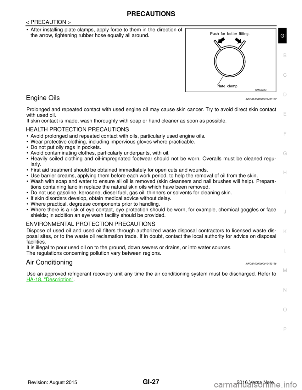
• After installing plate clamps, apply force to them in the direction of the arrow, tightening rubber hose equally all around.
Engine OilsINFOID:0000000012433167
Prolonged and repeated contact with used engine oil may cause skin cancer. Try to avoid direct skin contact
with used oil.
If skin contact is made, wash thoroughly with soap or hand cleaner as soon as possible.
HEALTH PROTECTION PRECAUTIONS
• Avoid prolonged and repeated contact with oils, particularly used engine oils.
• Wear protective clothing, including impervious gloves where practicable.
• Do not put oily rags in pockets.
• Avoid contaminating clothes, particularly underpants, with oil.
• Heavily soiled clothing and oil-impregnated footwear should not be worn. Overalls must be cleaned regu-
larly.
• First aid treatment should be obtained immediately for open cuts and wounds.
• Use barrier creams, applying them before each work period, to help the removal of oil from the skin.
• Wash with soap and water to ensure all oil is removed (skin cleansers and nail brushes will help). Prepara-
tions containing lanolin replace the natural skin oils which have been removed.
• Do not use gasoline, kerosene, diesel fuel, gas oil, thinners or solvents for cleaning skin.
• If skin disorders develop, obtain medical advice without delay.
• Where practical, degrease components prior to handling.
• Where there is a risk of eye contact, eye protection should be worn, for example, chemical goggles or face shields; in addition an eye wash facility should be provided.
ENVIRONMENTAL PROTECTION PRECAUTIONS
Dispose of used oil and used oil filters through authorized waste disposal contractors to licensed waste dis-
posal sites, or to the waste oil reclamation trade. If in doubt, contact the local authority for advice on disposal
facilities.
It is illegal to pour used oil on to the ground, down sewers or drains, or into water sources.
The regulations concerning po llution vary between regions.
Air ConditioningINFOID:0000000012433168
Use an approved refrigerant recovery unit any time t he air conditioning system must be discharged. Refer to
HA-18, "
Description".
SMA022D
Revision: August 2015 2016 Versa Note
cardiagn.com
Page 2037 of 3641
HA-12
< SYSTEM DESCRIPTION >
COMPONENT PARTS
SYSTEM DESCRIPTION
COMPONENT PARTS
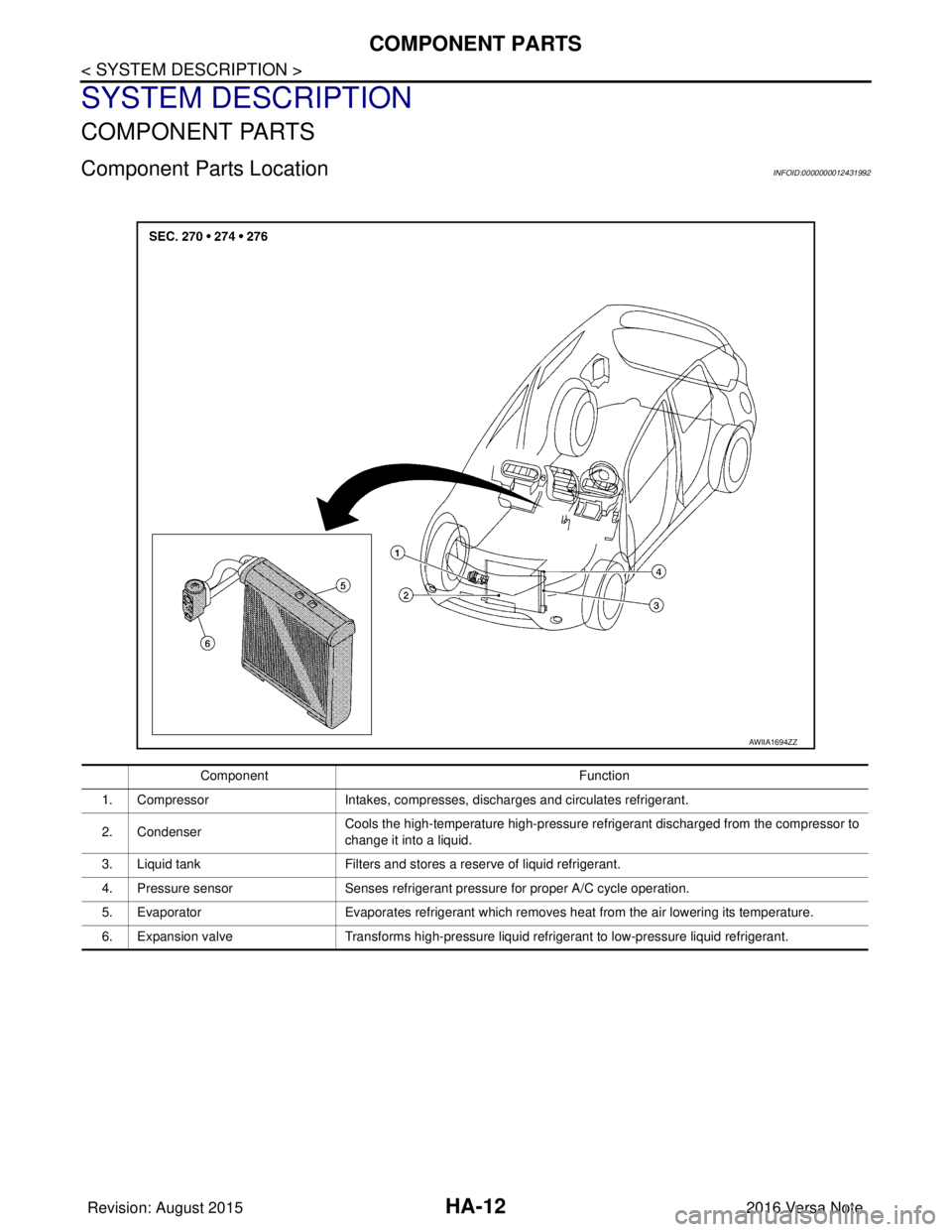
Component Parts LocationINFOID:0000000012431992
AWIIA1694ZZ
ComponentFunction
1. Compressor Intakes, compresses, discharges and circulates refrigerant.
2. Condenser Cools the high-temperature high-pressure refrigerant discharged from the compressor to
change it into a liquid.
3. Liquid tank Filters and stores a reserve of liquid refrigerant.
4. Pressure sensor Senses refrigerant pressure for proper A/C cycle operation.
5. Evaporator Evaporates refrigerant which removes heat from the air lowering its temperature.
6. Expansion valve Transforms high-pressure liquid refrigerant to low-pressure liquid refrigerant.
Revision: August 2015 2016 Versa Note
cardiagn.com
Page 2217 of 3641
![NISSAN NOTE 2016 Service Repair Manual LAN
SYSTEMLAN-29
< SYSTEM DESCRIPTION > [CAN]
C
D
E
F
G H
I
J
K L
B A
O P
N
*: These are the only control units wired with both ends of CAN communication system.
CAN COMMUNICATION SYSTEM : CAN
System NISSAN NOTE 2016 Service Repair Manual LAN
SYSTEMLAN-29
< SYSTEM DESCRIPTION > [CAN]
C
D
E
F
G H
I
J
K L
B A
O P
N
*: These are the only control units wired with both ends of CAN communication system.
CAN COMMUNICATION SYSTEM : CAN
System](/manual-img/5/57363/w960_57363-2216.png)
LAN
SYSTEMLAN-29
< SYSTEM DESCRIPTION > [CAN]
C
D
E
F
G H
I
J
K L
B A
O P
N
*: These are the only control units wired with both ends of CAN communication system.
CAN COMMUNICATION SYSTEM : CAN
System Specification ChartINFOID:0000000012433348
Determine CAN system type from the following specification chart.
NOTE:
Refer to LAN-16, "
Trouble Diagnosis Flow Chart" for how to use CAN system specification chart.
×: Applicable
VEHICLE EQUIPMENT IDENTIFICATION INFORMATION
NOTE:
Check CAN system type from the vehicle shape and equipment.
Noise filter It eliminates noise of CAN communication signal.
Termination circuit
*
(Resistance of approx. 120 Ω) Generates a potential difference between CAN-H and CAN-L.
Component
System description
Body type Hatch back
Axle 2WD
Engine HR16DE
Transmission M/T CVT
Brake control VDC
Around view monitor system ××
Navigation system ×××
CAN system type 501502 503505 504
CAN communication control unit
ECM ×××××
ABS actuator and electric unit (control unit) ×××××
IPDM E/R ×××××
TCM ×××
Around view monitor control unit ××
Air bag diagnosis sensor unit ×××××
AV c o n t r o l u n i t ×××
Data link connector ×××××
EPS control unit ×××××
Combination meter ×××××
Steering angle sensor ×××××
BCM ×××××
Revision: August 2015 2016 Versa Note
cardiagn.com
Page 2316 of 3641
MA-1
MAINTENANCE
C
DE
F
G H
I
J
K L
M B
MA
SECTION MA
N
O A
CONTENTS
MAINTENANCE
PRECAUTION .......
........................................3
PRECAUTIONS .............................................. .....3
Precaution for Supplemental Restraint System
(SRS) "AIR BAG" and "SEAT BELT PRE-TEN-
SIONER" ............................................................. ......
3
PREPARATION ............................................4
PREPARATION .............................................. .....4
Special Service Tool ........................................... ......4
Commercial Service Tool ..........................................4
PERIODIC MAINTENANCE ..........................5
GENERAL MAINTE NANCE ........................... .....5
Explanation of General Maintenance .................. ......5
PERIODIC MAINTENANCE ................................7
Introduction of Periodic Maintenance .................. ......7
RECOMMENDED FLUIDS AND LUBRI-
CANTS ................................................................
11
Fluids and Lubricants .......................................... ....11
Engine Oil Recommendation ..................................12
Anti-Freeze Coolant Mixture Ratio ..........................12
ENGINE MAINTENANCE ...................................13
DRIVE BELT .......................................................... ....13
DRIVE BELT : Exploded View ................................13
DRIVE BELT : Removal and Installation .................13
DRIVE BELT : Inspection .................................... ....14
DRIVE BELT : Adjustment ......................................14
ENGINE COOLANT ............................................... ....15
ENGINE COOLANT : Inspection .............................15
ENGINE COOLANT : Draining Engine Coolant ......16
ENGINE COOLANT : Refilling ................................16
ENGINE COOLANT : Flushing Cooling System .....18
FUEL LINES .......................................................... ....18
FUEL LINES : Inspection ........................................18
AIR CLEANER FILTER ......................................... ....18
AIR CLEANER FILTER : Exploded View ................19
AIR CLEANER FILTER : Removal and Installation
....
19
ENGINE OIL ........................................................... ....20
ENGINE OIL : Inspection .........................................20
ENGINE OIL : Draining ............................................21
ENGINE OIL : Refilling ............................................21
OIL FILTER ............................................................ ....22
OIL FILTER : Removal and Installation ...................22
SPARK PLUG ........................................................ ....22
SPARK PLUG : Exploded View ...............................23
SPARK PLUG : Removal and Installation ...............23
EVAP VAPOR LINES ............................................ ....25
EVAP VAPOR LINES : Inspection ...........................25
CHASSIS AND BODY MAINTENANCE ...........26
EXHAUST SYSTEM . ..................................................26
EXHAUST SYSTEM : Inspec tion ............................26
CVT FLUID ............................................................. ....26
CVT FLUID : Inspection ...........................................26
CVT FLUID : Replacement ......................................26
CVT FLUID : Adjustment .........................................28
CLUTCH FLUID ..................................................... ....29
CLUTCH FLUID : Inspection ...................................29
CLUTCH FLUID : Draining ......................................29
CLUTCH FLUID : Refilling .......................................30
GEAR OIL .............................................................. ....31
GEAR OIL : Inspection ............................................31
GEAR OIL : Draining ...............................................31
GEAR OIL : Refilling ................................................32
WHEELS ................................................................ ....32
WHEELS : Inspection ..............................................32
WHEELS : Adjustment ............................................32
Revision: August 2015 2016 Versa Note
cardiagn.com
Page 2322 of 3641
PERIODIC MAINTENANCEMA-7
< PERIODIC MAINTENANCE >
C
DE
F
G H
I
J
K L
M B
MA
N
O A
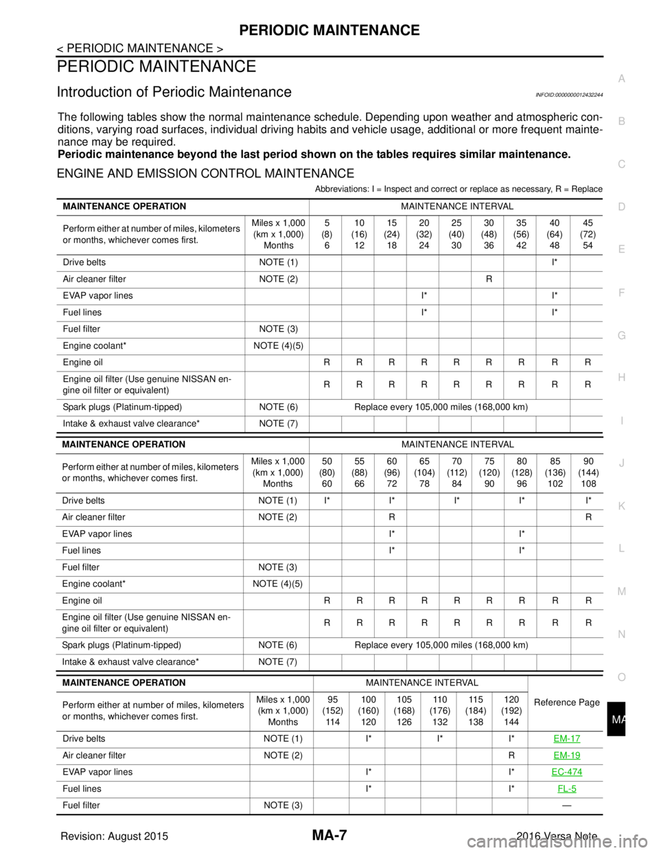
PERIODIC MAINTENANCE
Introduction of Periodic MaintenanceINFOID:0000000012432244
The following tables show the normal maintenanc
e schedule. Depending upon weather and atmospheric con-
ditions, varying road surfaces, indi vidual driving habits and vehicle usage, additional or more frequent mainte-
nance may be required.
Periodic maintenance beyond th e last period shown on the tables requires similar maintenance.
ENGINE AND EMISSION CONTROL MAINTENANCE
Abbreviations: I = Inspect and correct or replace as necessary, R = Replace
MAINTENANCE OPERATION MAINTENANCE INTERVAL
Perform either at number of miles, kilometers
or months, whichever comes first. Miles x 1,000
(km x 1,000) Months 5
(8) 6 10
(16) 12 15
(24) 18 20
(32) 24 25
(40) 30 30
(48) 36 35
(56) 42 40
(64) 48 45
(72) 54
Drive belts NOTE (1) I*
Air cleaner filter NOTE (2) R
EVAP vapor lines I*I*
Fuel lines I*I*
Fuel filter NOTE (3)
Engine coolant* NOTE (4)(5)
Engine oil RRRRRRR R R
Engine oil filter (Use genuine NISSAN en-
gine oil filter or equivalent) RRRRRRR R R
Spark plugs (Platinum-tipped) NOTE (6)Replace every 105,000 miles (168,000 km)
Intake & exhaust valve clearance* NOTE (7)
MAINTENANCE OPERATION MAINTENANCE INTERVAL
Perform either at number of miles, kilometers
or months, whichever comes first. Miles x 1,000
(km x 1,000) Months 50
(80) 60 55
(88) 66 60
(96) 72 65
(104) 78 70
(112) 84 75
(120) 90 80
(128) 96 85
(136) 102 90
(144) 108
Drive belts NOTE (1) I*I*I* I* I*
Air cleaner filter NOTE (2)R R
EVAP vapor lines I*I*
Fuel lines I*I*
Fuel filter NOTE (3)
Engine coolant* NOTE (4)(5)
Engine oil RRRRRRR R R
Engine oil filter (Use genuine NISSAN en-
gine oil filter or equivalent) RRRRRRR R R
Spark plugs (Platinum-tipped) NOTE (6)Replace every 105,000 miles (168,000 km)
Intake & exhaust valve clearance* NOTE (7)
MAINTENANCE OPERATION MAINTENANCE INTERVAL
Reference Page
Perform either at number of miles, kilometers
or months, whichever comes first. Miles x 1,000
(km x 1,000)
Months 95
(152)
11 4 100
(160)
120 105
(168)
126 11 0
(176)
132 11
5
(184)
138 12
0
(192)
14
4
Drive belts NOTE (1)I*I*I*EM-17
Air cleaner filter NOTE (2) REM-19
EVAP vapor lines I*I*EC-474
Fuel lines I*I*FL-5
Fuel filter NOTE (3) —
Revision: August 2015 2016 Versa Note
cardiagn.com