2016 NISSAN NOTE wheel
[x] Cancel search: wheelPage 2426 of 3641
![NISSAN NOTE 2016 Service Repair Manual MWI-68
< SYSTEM DESCRIPTION >[TYPE B]
OPERATION
OPERATION
Switch Name and FunctionINFOID:0000000012432610
ILLUMINATION CONTROL SWITCH/
TRIP ODOMETER RESET SWITCH
STEERING WHEEL AUDIO CONTROL SWITCH (M NISSAN NOTE 2016 Service Repair Manual MWI-68
< SYSTEM DESCRIPTION >[TYPE B]
OPERATION
OPERATION
Switch Name and FunctionINFOID:0000000012432610
ILLUMINATION CONTROL SWITCH/
TRIP ODOMETER RESET SWITCH
STEERING WHEEL AUDIO CONTROL SWITCH (M](/manual-img/5/57363/w960_57363-2425.png)
MWI-68
< SYSTEM DESCRIPTION >[TYPE B]
OPERATION
OPERATION
Switch Name and FunctionINFOID:0000000012432610
ILLUMINATION CONTROL SWITCH/
TRIP ODOMETER RESET SWITCH
STEERING WHEEL AUDIO CONTROL SWITCH (METER CONTROL SWITCH)
AWNIA3606ZZ
Switch name Operation Description
Illumination control switch (1) Turn An illuminance level of the back light of the combination meter can be adjusted.
Trip odometer reset switch (1) Press • The information display screen can be switched.
• The trip meter can be switched between A and B.
• Trip meter A/B can be reset by pressing and holding the trip reset switch.
• Time can be adjusted.
AWNIA3620GB
Switch name
Operation Description
Steering wheel audio control switch
(meter control switch) (2) Press• Trip computer modes can be selected.
• Trip computer value displayed can be reset by pressing and holding the meter
control switch for 1 second or more.
• All trip computer values displayed can be reset by pressing and holding the
meter control switch for 3 seconds or more.
Revision: August 2015 2016 Versa Note
cardiagn.com
Page 2501 of 3641

PB-8
< REMOVAL AND INSTALLATION >
PARKING BRAKE REAR CABLE
PARKING BRAKE REAR CABLE
Removal and InstallationINFOID:0000000012430692
REMOVAL
1. Remove the center console assembly. Refer to IP-18, "Removal and Installation".
2. Loosen the adjusting nut. Refer to PB-6, "
Exploded View".
NOTE:
It is not necessary to remove the parking brake front cable.
3. Separate the parking brake rear cables (RH/LH ) from the parking brake front cable. Refer to PB-6,
"Exploded View".
4. Remove the rear wheels and tires using power tool. Refer to WT-48, "
Exploded View".
5. Remove rear wheel sensors. Refer to BRC-143, "
REAR SENSOR ROTOR : Removal and Installation".
6. Remove the rear drum brake components. Refer to BR-41, "
Removal and Installation".
CAUTION:
Do not separate the brake tube from the wheel cylinders.
7. Remove the center muffler. Refer to EX-5, "
Exploded View".
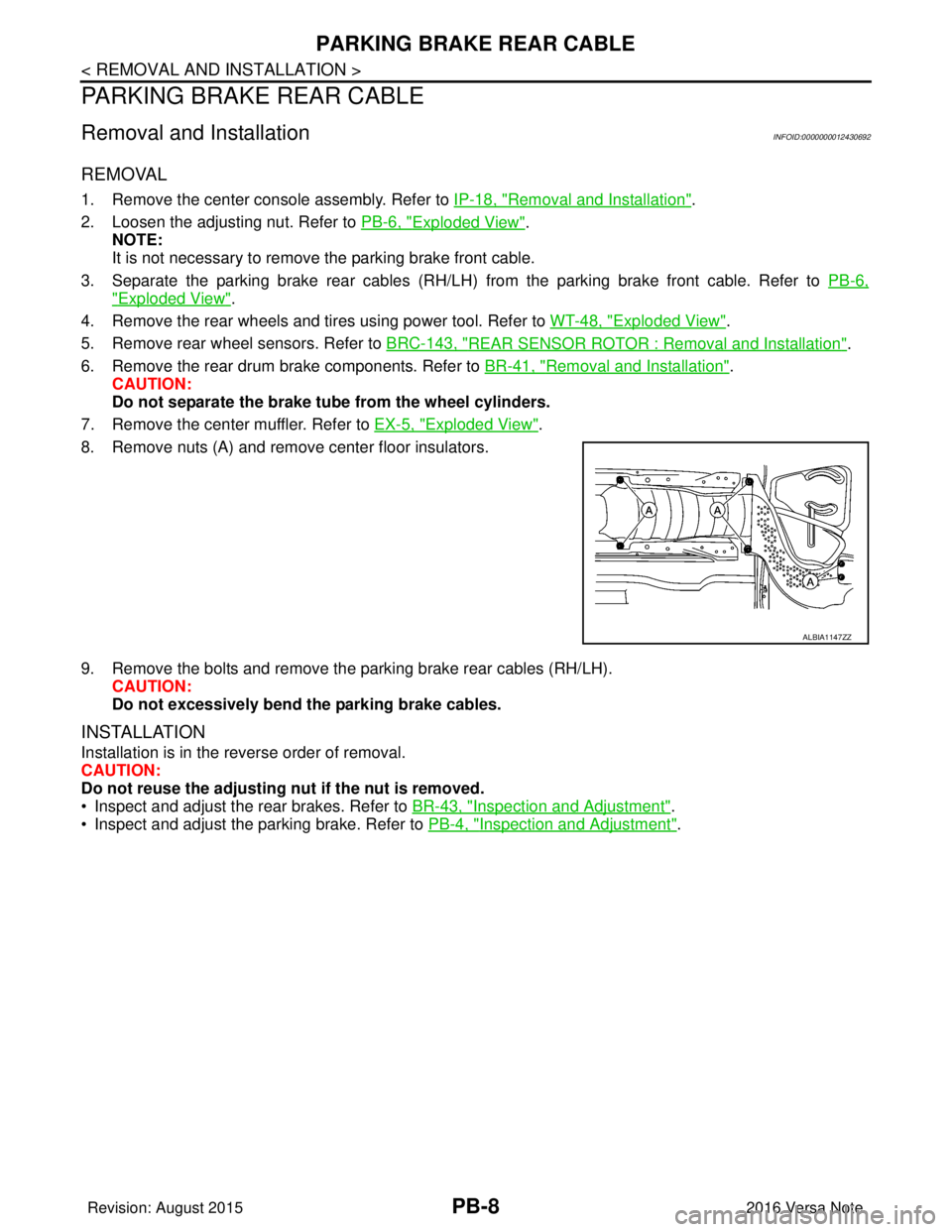
8. Remove nuts (A) and remove center floor insulators.
9. Remove the bolts and remove the parking brake rear cables (RH/LH). CAUTION:
Do not excessively bend the parking brake cables.
INSTALLATION
Installation is in the reverse order of removal.
CAUTION:
Do not reuse the adjusting nut if the nut is removed.
• Inspect and adjust the rear brakes. Refer to BR-43, "
Inspection and Adjustment".
• Inspect and adjust the parking brake. Refer to PB-4, "
Inspection and Adjustment".
ALBIA1147ZZ
Revision: August 2015 2016 Versa Note
cardiagn.com
Page 2633 of 3641

PG-46
< WIRING DIAGRAM >
HARNESS
D3 E4 Y/2 : Crash zone sensorE1 E42 B/2: IPDM E/R (Intelligent power distribution
module engine room)
E4 E5 B/2 : Cooling fan motor (With CVT)E2 E43 B/6: IPDM E/R (Intelligent power distribution
module engine room)
E2 E8 W/24 : To F8 F2 E44 BR/8: IPDM E/R (Intelligent power distribution
module engine room)
E3 E9 BR/2 : Fusible link b o x ( B a t t e r y )E 1 E 4 5 B R / 1 2: IPDM E/R (Intelligent power distribution
module engine room)
E2 E10 GR/2 : Fusible link box (Battery) F2 E46 W/24: IPDM E/R (Intelligent power distribution
module engine room)
G 2 E 1 5 — : B o d y g r o u n d F 2 E 4 7 W / 1 6: IPDM E/R (Intelligent power distribution
module engine room)
F 2 E 1 6 B / 3 2 : E C M B 3 E 5 0 B R / 2 : W a s h e r f l u i d l e v e l s w i t c h
F4 E17 B/3 : Refrigerant pressure sensor E3 E51 B/2 : Front wheel sensor LH
C4 E18 BR/1 : Horn C4 E52 B/2 : Front wheel sensor RH
E 2 E 1 9 W / 6 : To F 3 3 G 4 E 5 3 B / 2 : F r o n t f o g l a m p L H
C 4 E 2 0 B / 1 : H o r n B 5 E 5 4 B / 2 : F r o n t f o g l a m p R H
A2 E24 — : Body ground E2 E55 GR/12 : To F55
G3 E25 B/3 : Front combination lamp LH G3 E62 L/4 : Cooling fan relay
A3 E26 B/3 : Front combination lamp RH C3 E63 GR/4 : Heated oxygen sensor 2
G2 E27 B/2 : Front combination lamp LH C4 E64 L/4 : Heated seat relay
A2 E28 B/2 : Front combinati on lamp RHG5 E69 B/2 : Ambient sensor
F4 E29 GR/3 : Front combination lamp LH E5 E70 BR/3 : Intelligent Key warning buzzer
B3 E30 GR/3 : Front combination lamp RH F5 E71 B/4 : Front camera
E3 E31 GR/4 : Cooling fan motor (With CVT) G3 E72 L/4 : Active grille shutter relay
E4 E32 W/2 : Cooling fan motor (With CVT) Front fog lamp sub harness
B2 E33 B/38 : ABS actuator and electric unit (Control
unit) E5 E302 B/4 : To E35
E5 E35 B/4 : To E302 F5 E303 B/4 : Active grille shutter
E1 E39 W/3 : Horn relay F5 E303 B/4 : Active grille shutter
Revision: August 2015 2016 Versa Note
cardiagn.com
Page 2637 of 3641

PG-50
< WIRING DIAGRAM >
HARNESS
BODY HARNESS
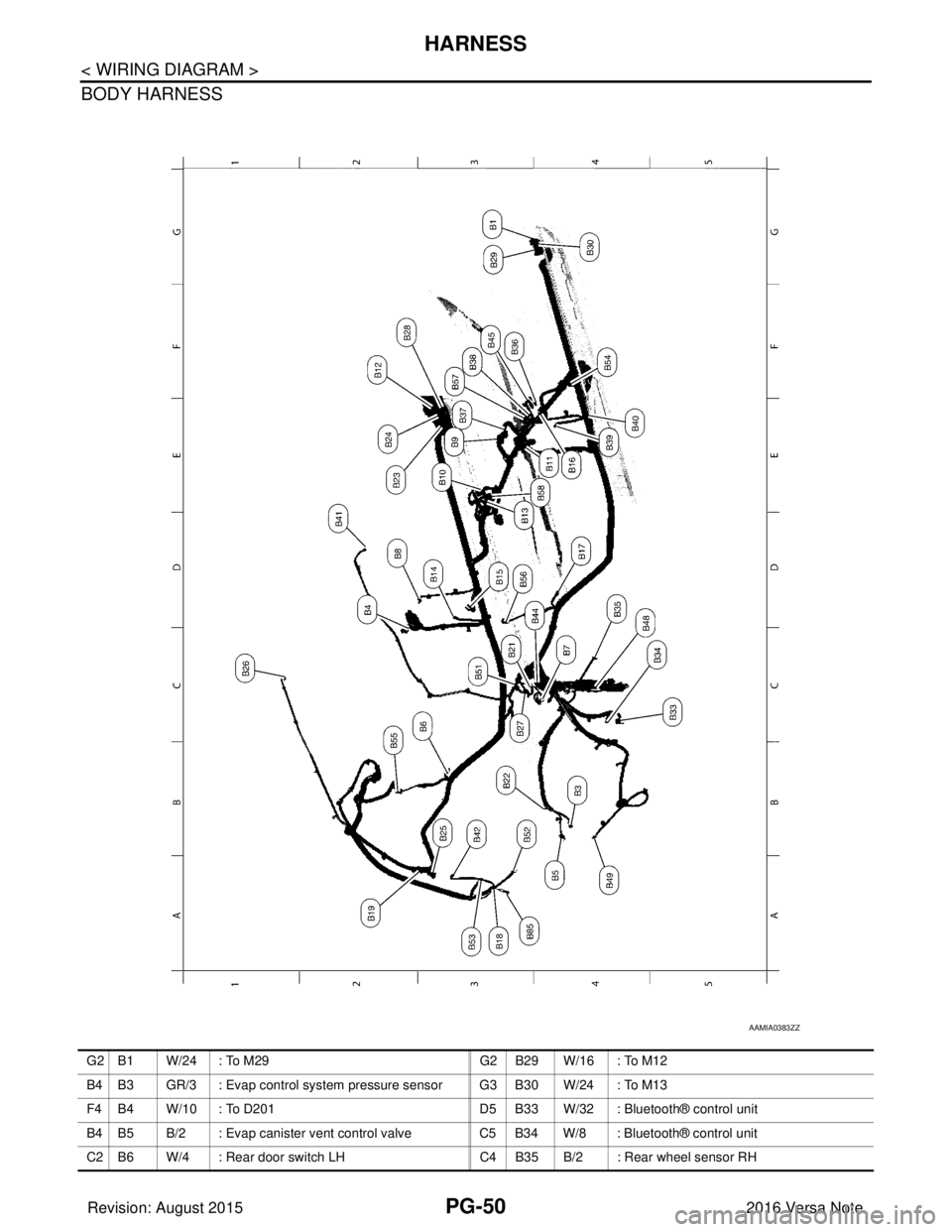
AAMIA0383ZZ
G 2 B 1 W / 2 4 : To M 2 9G 2 B 2 9 W / 1 6 : To M 1 2
B4 B3 GR/3 : Evap control system pressure sensor G3 B30 W/24 : To M13
F4 B4 W/10 : To D201 D5 B33 W/32 : Bluetooth® control unit
B4 B5 B/2 : Evap canister vent control valve C5 B34 W/8 : Bluetooth® control unit
C2 B6 W/4 : Rear door switch LH C4 B35 B/2 : Rear wheel sensor RH
Revision: August 2015 2016 Versa Note
cardiagn.com
Page 2638 of 3641

PG
HARNESSPG-51
< WIRING DIAGRAM >
C
DE
F
G H
I
J
K L
B A
O P
N
D4 B7 — : Body ground
F3 B36 W/4 : To B350
D2 B8 W/4 : Front door switch LH F2 B37 Y/22 : Air bag diagnosis sensor unit
E2 B9 Y/22 : Air bag diagnosis sensor unit F2 B38 Y/2 : Front RH side air bag module
D2 B10 Y/2 : Front LH side air bag module F4 B39 Y/2 : Front RH seat belt pre–tensioner
E3 B11 W/10 : To D301 G3 B40 Y/2 : Side air bag satellite sensor RH
E1 B12 GR/16 : To E21 D4 B41 Y/2 : RH side curtain air bag module
E3 B13 W/3 : Seat belt buckle switch LH B3 B42 B/1 : Condenser
D2 B14 Y/2 : Front LH seat belt pre–tensioner D3 B44 GR/5 : Fuel level sensor unit and fuel pump
C2 B15 Y/2 : Side air bag satellite sensor LH F2 B45 W/3 : Seat belt buckle switch RH
E3 B16 W/4 : Front door switch RH C4 B48 L/2 : Inside key antenna (Trunk room)
E4 B17 W/4 : Rear door switch RH B5 B49 L/2 : Outside key antenna (Rear bumper)
B3 B18 B/2 : High–mounted stop lamp C3 B51 B/1 : Rear window defogger
A2 B19 — : Body ground B3 B52 W/4 : To D504
D 4 B 2 1 W / 4 : C a r g o l a m p A 4 B 5 3 W / 8 : To D 5 0 3
C3 B22 GR/2 : Rear wheel sensor LH G2 B54 W/40 : Around view monitor control unit
F2 B23 W/16 : To M15 C2 B55 Y/2 : Rear side air bag satellite sensor LH
F1 B24 W/24 : To M16 D3 B56 Y/2 : Rear side air bag satellite sensor RH
A3 B25 W/6 : Rear combination lamp LH F2 B57 GR/3 : Seat heater RH
C1 B26 Y/2 : LH side curtain air bag module E3 B58 GR/3 : Seat heater LH
C4 B27 W/6 : Rear combination lamp RH A4 B85 — : Body ground
E 1 B 2 8 W / 2 : To M 1 1
Revision: August 2015 2016 Versa Note
cardiagn.com
Page 2719 of 3641

RAX-1
TRANSMISSION & DRIVELINE
CEF
G H
I
J
K L
M
SECTION RAX
A
B
RAX
N
O P
CONTENTS
REAR AXLE
PRECAUTION ....... ........................................2
PRECAUTIONS .............................................. .....2
Precaution for Supplemental Restraint System
(SRS) "AIR BAG" and "SEAT BELT PRE-TEN-
SIONER" ............................................................. ......
2
Precautions for Wheel Hub .......................................2
PREPARATION ............................................3
PREPARATION .............................................. .....3
Special Service Tools .......................................... ......3
Commercial Service Tool ..........................................3
SYMPTOM DIAGNOSIS ...............................4
NOISE, VIBRATION AND HARSHNESS
(NVH) TROUBLESHOOTING ........................ .....
4
NVH Troubleshooting Chart ................................ ......4
PERIODIC MAINTENANCE .........................5
REAR WHEEL HUB ...........................................5
Inspection ............................................................ .....5
REMOVAL AND INSTALLATION ................6
REAR WHEEL HUB ...........................................6
Exploded View ..................................................... .....6
Removal and Installation ..........................................6
Disassembly and Assembly ......................................7
Inspection .................................................................9
SERVICE DATA AND SPECIFICATIONS
(SDS) ............... .......................................... ...
10
SERVICE DATA AND SPECIFICATIONS
(SDS) .................................................................
10
Wheel Bearing ..................................................... ....10
Wheel Hub ...............................................................10
Revision: August 2015 2016 Versa Note
cardiagn.com
Page 2720 of 3641

RAX-2
< PRECAUTION >
PRECAUTIONS
PRECAUTION
PRECAUTIONS
Precaution for Supplemental Restraint System (SRS) "AIR BAG" and "SEAT BELT
PRE-TENSIONER"
INFOID:0000000012431904
The Supplemental Restraint System such as “A IR BAG” and “SEAT BELT PRE-TENSIONER”, used along
with a front seat belt, helps to reduce the risk or severity of injury to the driver and front passenger for certain
types of collision. Information necessary to service the system safely is included in the SR and SB section of
this Service Manual.
WARNING:
• To avoid rendering the SRS inopera tive, which could increase the risk of personal injury or death in
the event of a collision which would result in air bag inflation, all maintenance must be performed by
an authorized NISSAN/INFINITI dealer.
• Improper maintenance, including in correct removal and installation of the SRS, can lead to personal
injury caused by unintent ional activation of the system. For re moval of Spiral Cable and Air Bag
Module, see the SR section.
• Do not use electrical test equipmen t on any circuit related to the SRS unless instructed to in this
Service Manual. SRS wiring harn esses can be identified by yellow and/or orange harnesses or har-
ness connectors.
PRECAUTIONS WHEN USING POWER TOOLS (AIR OR ELECTRIC) AND HAMMERS
WARNING:
• When working near the Airbag Diagnosis Sensor Unit or other Airbag System sensors with the Igni-
tion ON or engine running, DO NOT use air or electri c power tools or strike near the sensor(s) with a
hammer. Heavy vibration could activate the sensor( s) and deploy the air bag(s), possibly causing
serious injury.
• When using air or electric power tools or hammers , always switch the Ignition OFF, disconnect the
battery and wait at least three minutes before performing any service.
Precautions for Wheel HubINFOID:0000000012431905
Observe the following precautions when assembling wheel hub.
• Perform work in a location that is free from dust, dirt and debris.
• Use paper shop towels while performing repairs. Fabric shop cloths must not be used because of the danger of lint adhering to parts.
• Do not drop any of the components such as the brake drum, wheel bearing, spindle, or wheel hub lock nut. If
any of these parts have been dropped, they must be replaced.
• Always check that the tools used to press-fit the wheel bearing to the brake drum have no wear and defor-
mation. Damaged tools will not guarantee that pre ssure can be applied vertically and damage parts.
Revision: August 2015 2016 Versa Note
cardiagn.com
Page 2721 of 3641

PREPARATIONRAX-3
< PREPARATION >
CEF
G H
I
J
K L
M A
B
RAX
N
O P
PREPARATION
PREPARATION
Special Service ToolsINFOID:0000000012431906
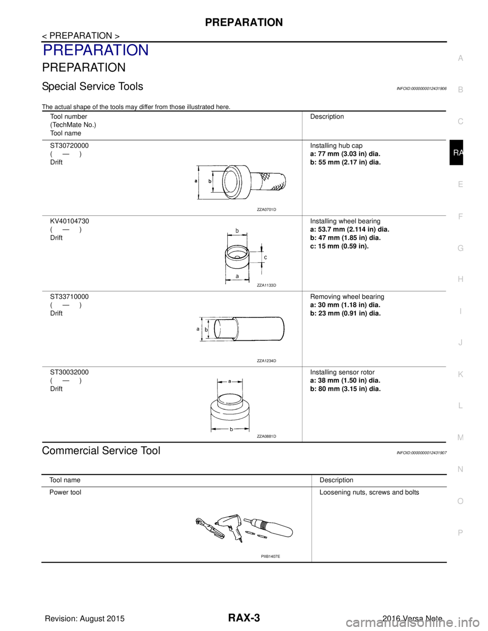
The actual shape of the tools may di ffer from those illustrated here.
Commercial Service ToolINFOID:0000000012431907
Tool number
(TechMate No.)
Tool name Description
ST30720000
(—)
Drift Installing hub cap
a: 77 mm (3.03 in) dia.
b: 55 mm (2.17 in) dia.
KV40104730
(—)
Drift Installing wheel bearing
a: 53.7 mm (2.114 in) dia.
b: 47 mm (1.85 in) dia.
c: 15 mm (0.59 in).
ST33710000
(—)
Drift Removing wheel bearing
a: 30 mm (1.18 in) dia.
b: 23 mm (0.91 in) dia.
ST30032000
(—)
Drift Installing sensor rotor
a: 38 mm (1.50 in) dia.
b: 80 mm (3.15 in) dia.
ZZA0701D
ZZA1133D
ZZA1234D
ZZA0881D
Tool name
Description
Power tool Loosening nuts, screws and bolts
PIIB1407E
Revision: August 2015 2016 Versa Note
cardiagn.com