2016 NISSAN NOTE wheel
[x] Cancel search: wheelPage 2768 of 3641
C1704, C1705, C1706, C1707 LOW TIRE PRESSURE
WT-25
< DTC/CIRCUIT DIAGNOSIS >
C
D F
G H
I
J
K L
M A
B
WT
N
O P
DTC/CIRCUIT DIAGNOSIS
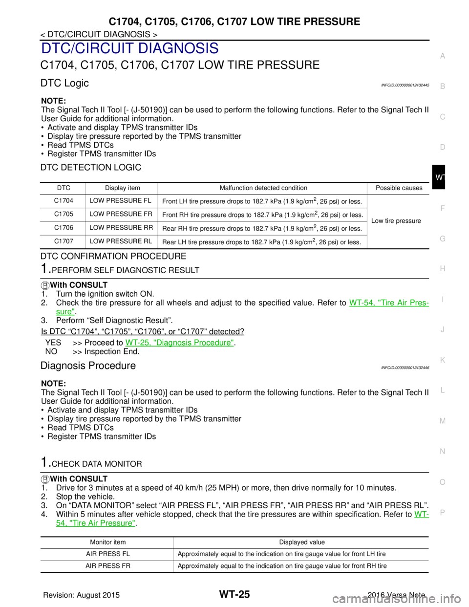
C1704, C1705, C1706, C1707 LOW TIRE PRESSURE
DTC LogicINFOID:0000000012432445
NOTE:
The Signal Tech II Tool [- (J-50190)] can be used to perform the following functions. Refer to the Signal Tech II
User Guide for additional information.
• Activate and display TPMS transmitter IDs
• Display tire pressure repor ted by the TPMS transmitter
• Read TPMS DTCs
• Register TPMS transmitter IDs
DTC DETECTION LOGIC
DTC CONFIRMATION PROCEDURE
1.PERFORM SELF DIAGNOSTIC RESULT
With CONSULT
1. Turn the ignition switch ON.
2. Check the tire pressure for all wheels and adjust to the specified value. Refer to WT-54, "
Tire Air Pres-
sure".
3. Perform “Self Diagnostic Result”.
Is DTC
“C1704”, “C1705”, “C1706”, or “C1707” detected?
YES >> Proceed to WT-25, "Diagnosis Procedure".
NO >> Inspection End.
Diagnosis ProcedureINFOID:0000000012432446
NOTE:
The Signal Tech II Tool [- (J-50190)] can be used to perform the following functions. Refer to the Signal Tech II
User Guide for additional information.
• Activate and display TPMS transmitter IDs
• Display tire pressure repor ted by the TPMS transmitter
• Read TPMS DTCs
• Register TPMS transmitter IDs
1.CHECK DATA MONITOR
With CONSULT
1. Drive for 3 minutes at a speed of 40 km/h (25 MPH) or more, then drive normally for 10 minutes.
2. Stop the vehicle.
3. On “DATA MONITOR” select “AIR PRESS FL”, “AIR PRESS FR”, “AIR PRESS RR” and “AIR PRESS RL”.
4. Within 5 minutes after vehicle stopped, check that the tire pressures are within specification. Refer to WT-
54, "Tire Air Pressure".
DTCDisplay item Malfunction detected condition Possible causes
C1704 LOW PRESSURE FL Front LH tire pressure drops to 182.7 kPa (1.9 kg/cm
2, 26 psi) or less.
Low tire pressure
C1705 LOW PRESSURE FR
Front RH tire pressure drops to 182.7 kPa (1.9 kg/cm
2, 26 psi) or less.
C1706 LOW PRESSURE RR Rear RH tire pressure drops to 182.7 kPa (1.9 kg/cm
2, 26 psi) or less.
C1707 LOW PRESSURE RL Rear LH tire pressure drops to 182.7 kPa (1.9 kg/cm
2, 26 psi) or less.
Monitor item Displayed value
AIR PRESS FL Approximately equal to the indication on tire gauge value for front LH tire
AIR PRESS FR Approximately equal to the indication on tire gauge value for front RH tire
Revision: August 2015 2016 Versa Note
cardiagn.com
Page 2770 of 3641
C1708, C1709, C1710, C1711 TRANSMITTER (NO DATA)
WT-27
< DTC/CIRCUIT DIAGNOSIS >
C
DF
G H
I
J
K L
M A
B
WT
N
O P
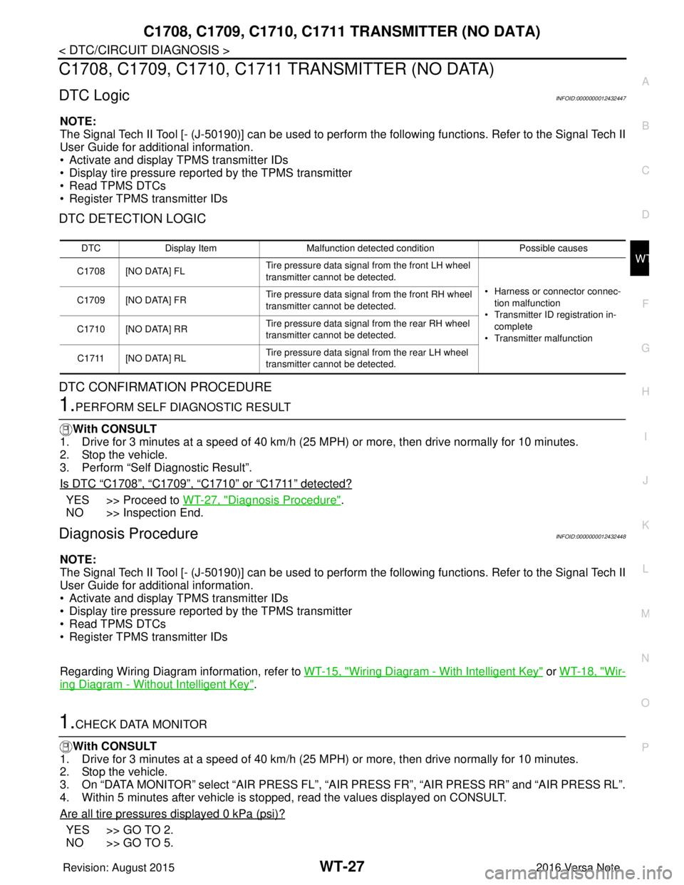
C1708, C1709, C1710, C1711 TRANSMITTER (NO DATA)
DTC LogicINFOID:0000000012432447
NOTE:
The Signal Tech II Tool [- (J-50190)] can be used to perform the following functions. Refer to the Signal Tech II
User Guide for additional information.
• Activate and display TPMS transmitter IDs
• Display tire pressure repor ted by the TPMS transmitter
• Read TPMS DTCs
• Register TPMS transmitter IDs
DTC DETECTION LOGIC
DTC CONFIRMATION PROCEDURE
1.PERFORM SELF DIAGNOSTIC RESULT
With CONSULT
1. Drive for 3 minutes at a speed of 40 km/h (25 MPH) or more, then drive normally for 10 minutes.
2. Stop the vehicle.
3. Perform “Self Diagnostic Result”.
Is DTC
“C1708”, “C1709”, “C1710” or “C1711” detected?
YES >> Proceed to WT-27, "Diagnosis Procedure".
NO >> Inspection End.
Diagnosis ProcedureINFOID:0000000012432448
NOTE:
The Signal Tech II Tool [- (J-50190)] can be used to perform the following functions. Refer to the Signal Tech II
User Guide for additional information.
• Activate and display TPMS transmitter IDs
• Display tire pressure repor ted by the TPMS transmitter
• Read TPMS DTCs
• Register TPMS transmitter IDs
Regarding Wiring Diagram information, refer to WT-15, "
Wiring Diagram - With Intelligent Key" or WT-18, "Wir-
ing Diagram - Without Intelligent Key".
1.CHECK DATA MONITOR
With CONSULT
1. Drive for 3 minutes at a speed of 40 km/h (25 MPH) or more, then drive normally for 10 minutes.
2. Stop the vehicle.
3. On “DATA MONITOR” select “AIR PRESS FL”, “AIR PRESS FR”, “AIR PRESS RR” and “AIR PRESS RL”.
4. Within 5 minutes after vehicle is stopped, read the values displayed on CONSULT.
Are all tire pressures displayed 0 kPa (psi)?
YES >> GO TO 2.
NO >> GO TO 5.
DTC Display Item Malfunction detected condition Possible causes
C1708 [NO DATA] FL Tire pressure data signal from the front LH wheel
transmitter cannot be detected.
• Harness or connector connec-tion malfunction
• Transmitter ID registration in- complete
• Transmitter malfunction
C1709 [NO DATA] FR
Tire pressure data signal from the front RH wheel
transmitter cannot be detected.
C1710 [NO DATA] RR Tire pressure data signal from the rear RH wheel
transmitter cannot be detected.
C1711 [NO DATA] RL Tire pressure data signal from the rear LH wheel
transmitter cannot be detected.
Revision: August 2015
2016 Versa Note
cardiagn.com
Page 2773 of 3641
WT-30
< DTC/CIRCUIT DIAGNOSIS >
C1716, C1717, C1718, C1719 TRANSMITTER (PRESSURE DATA)
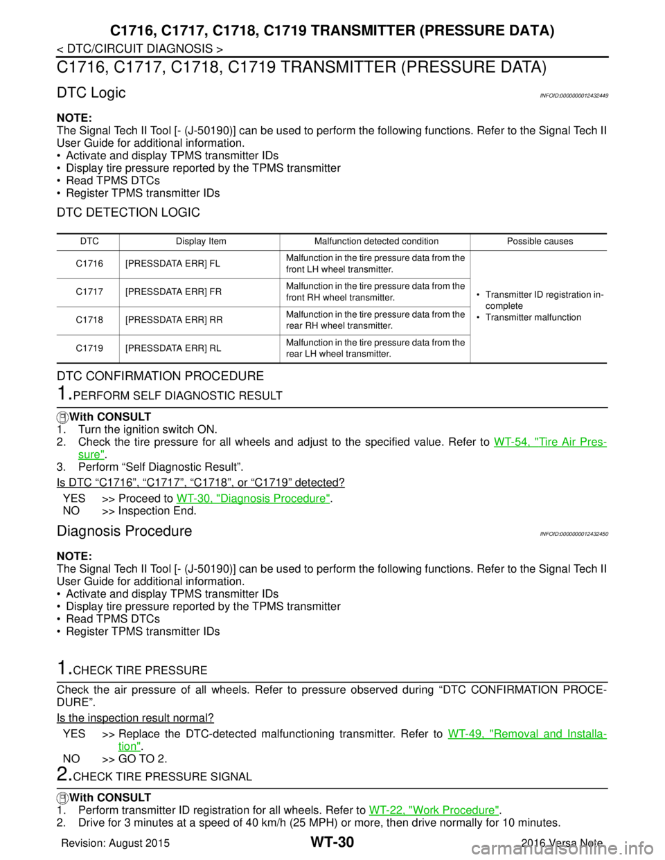
C1716, C1717, C1718, C1719 TRAN SMITTER (PRESSURE DATA)
DTC LogicINFOID:0000000012432449
NOTE:
The Signal Tech II Tool [- (J-50190)] can be used to perform the following functions. Refer to the Signal Tech II
User Guide for additional information.
• Activate and display TPMS transmitter IDs
• Display tire pressure reported by the TPMS transmitter
• Read TPMS DTCs
• Register TPMS transmitter IDs
DTC DETECTION LOGIC
DTC CONFIRMATION PROCEDURE
1.PERFORM SELF DIAGNOSTIC RESULT
With CONSULT
1. Turn the ignition switch ON.
2. Check the tire pressure for all wheels and adjust to the specified value. Refer to WT-54, "
Tire Air Pres-
sure".
3. Perform “Self Diagnostic Result”.
Is DTC
“C1716”, “C1717”, “C1718”, or “C1719” detected?
YES >> Proceed to WT-30, "Diagnosis Procedure".
NO >> Inspection End.
Diagnosis ProcedureINFOID:0000000012432450
NOTE:
The Signal Tech II Tool [- (J-50190)] can be used to perform the following functions. Refer to the Signal Tech II
User Guide for additional information.
• Activate and display TPMS transmitter IDs
• Display tire pressure reported by the TPMS transmitter
• Read TPMS DTCs
• Register TPMS transmitter IDs
1.CHECK TIRE PRESSURE
Check the air pressure of all wheels. Refer to pressure observed during “DTC CONFIRMATION PROCE-
DURE”.
Is the inspection result normal?
YES >> Replace the DTC-detected malfunctioning transmitter. Refer to WT-49, "Removal and Installa-
tion".
NO >> GO TO 2.
2.CHECK TIRE PRESSURE SIGNAL
With CONSULT
1. Perform transmitter ID regist ration for all wheels. Refer to WT-22, "
Work Procedure".
2. Drive for 3 minutes at a speed of 40 km/h (25 MPH) or more, then drive normally for 10 minutes.
DTC Display Item Malfunction detected condition Possible causes
C1716 [PRESSDATA ERR] FL Malfunction in the tire pressure data from the
front LH wheel transmitter.
• Transmitter ID registration in-
complete
• Transmitter malfunction
C1717 [PRESSDATA ERR] FR
Malfunction in the tire pressure data from the
front RH wheel transmitter.
C1718 [PRESSDATA ERR] RR Malfunction in the tire pressure data from the
rear RH wheel transmitter.
C1719 [PRESSDATA ERR] RL Malfunction in the tire pressure data from the
rear LH wheel transmitter.
Revision: August 2015
2016 Versa Note
cardiagn.com
Page 2786 of 3641

NOISE, VIBRATION AND HARSHNESS (NVH) TROUBLESHOOTINGWT-43
< SYMPTOM DIAGNOSIS >
C
DF
G H
I
J
K L
M A
B
WT
N
O P
NOISE, VIBRATION AND HARSHN ESS (NVH) TROUBLESHOOTING
NVH Troubleshooting ChartINFOID:0000000012432464
Use chart below to find the cause of the symptom . If necessary, repair or replace these parts.
×: Applicable
Reference page
WT-44WT-44WT-45WT-54FSU-8—
—
WT-54FSU-5FA X - 6RAX-4RSU-4—
—
FA X - 6BR-7ST-7
Possible cause and SUSPECTED PARTS
Improper installation, looseness
Out-of-round
Imbalance
Incorrect tire pressure
Uneven tire wear
Deformation or damage
Non-uniformity
Incorrect tire size
FRONT AXLE AND FRONT SUSPENSION
REAR AXLE AND REAR SUSPENSION
TIRES
ROAD WHEELS
DRIVE SHAFT
BRAKE
STEERING
Symptom TIRENoise
××××××× × × ××××
Shake ×××××× × × × ××××
Vibration ××××××
Shimmy ×××××××× × × × ××
Shudder ×
××××× × × × × ××
Poor quality ride or
handling ×××××× × × ××
WHEEL Noise
××× × × × × ×××
Shake ××× × × × × ×××
Shimmy, Shudder ×××× ×××××
Poor quality ride or
handling ×× × ×
× × ×
Revision: August 2015 2016 Versa Note
cardiagn.com
Page 2787 of 3641
WT-44
< PERIODIC MAINTENANCE >
WHEEL
PERIODIC MAINTENANCE
WHEEL
InspectionINFOID:0000000012432465
1. Check tires for wear and improper inflation.
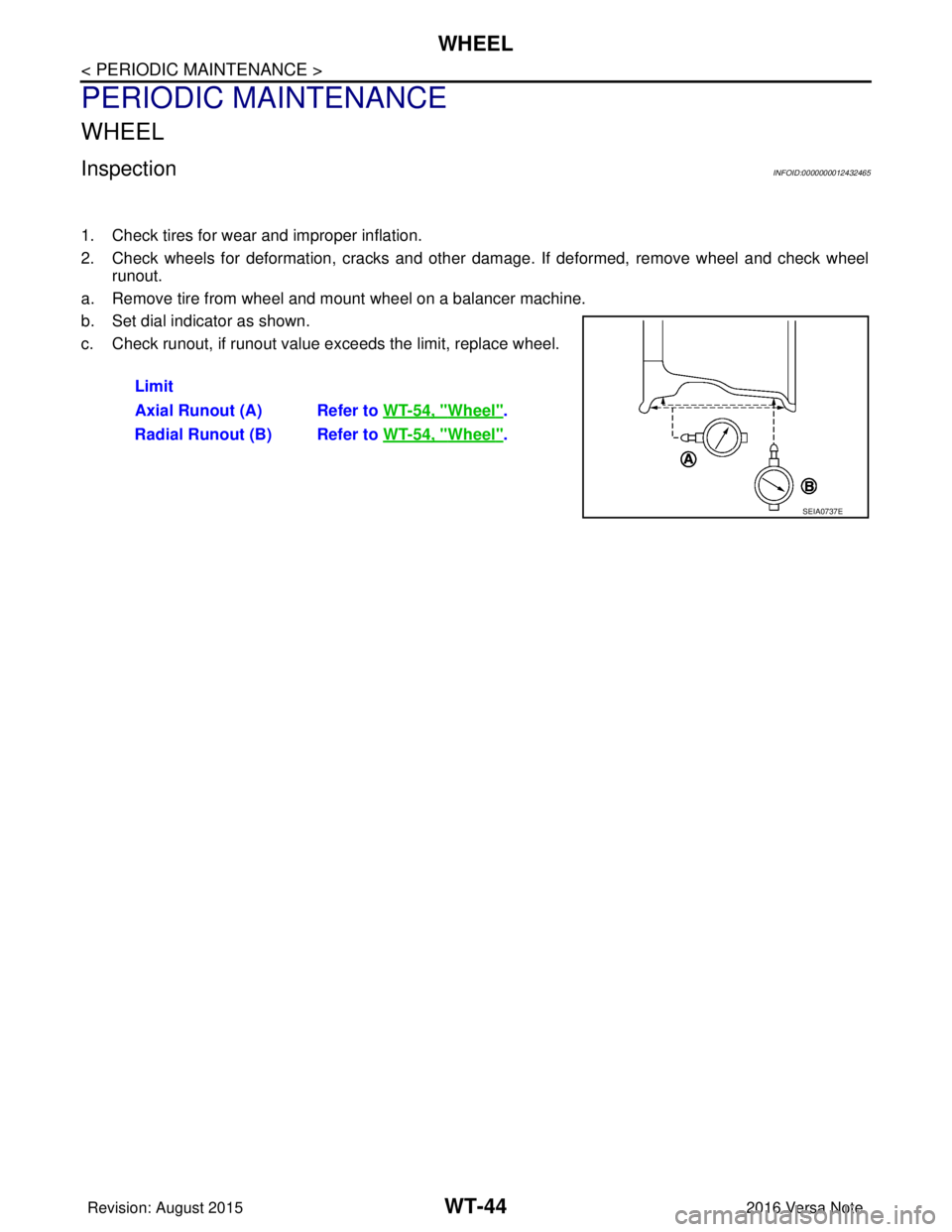
2. Check wheels for deformation, cracks and other damage. If deformed, remove wheel and check wheel
runout.
a. Remove tire from wheel and mount wheel on a balancer machine.
b. Set dial indicator as shown.
c. Check runout, if runout value exceeds the limit, replace wheel.
Limit
Axial Runout (A) Refer to WT-54, "
Wheel".
Radial Runout (B) Refer to WT-54, "
Wheel".
SEIA0737E
Revision: August 2015 2016 Versa Note
cardiagn.com
Page 2788 of 3641
WHEEL AND TIREWT-45
< PERIODIC MAINTENANCE >
C
DF
G H
I
J
K L
M A
B
WT
N
O P
WHEEL AND TIRE
AdjustmentINFOID:0000000012432466
BALANCING WHEELS (ADH ESIVE WEIGHT TYPE)
Preparation Before Adjustment
Remove inner and outer balance weights from the wheel and tire. Using releasing agent, remove double-faced
adhesive tape from the wheel and tire.
CAUTION:
• Be careful not to scratch the wheel and tire during removal.
• After removing double-faced ad hesive tape, wipe clean all traces of releasing agent from the wheel
and tire.
Wheel Balance Adjustment
CAUTION:
• DO NOT use center hole cone-type clamping machin es to hold the wheel during tire removal/installa-
tion or balancing or damage to the wheel paint, cl adding or chrome may result. Use only rim-type or
universal lug-type clamping machines to hold the wheel during servicing.
• If a balancer machine has an adhesive weight mode setting, select the adhesive weight mode setting and
skip Step 2 below. If a balancer machine only has the clip-on (rim flange) weight mode setting, follow Step 2
to calculate the correct size adhesive weight.
1. Set wheel and tire on balancer machine using the center hole as a guide. Start the balancer machine.
2. For balancer machines that only have a clip-on (rim fl ange) weight mode setting, follow this step to calcu-
late the correct size adhesive weight to use. W hen inner and outer imbalance values are shown on the
balancer machine indicator, multiply outer imbalance value by 5/3 (1.67) to determine balance weight that
should be used. Select the outer balance weight with a value closest to the calculated value above and
install in to the designated outer position of or at the designated angle in relation to the wheel and tire.
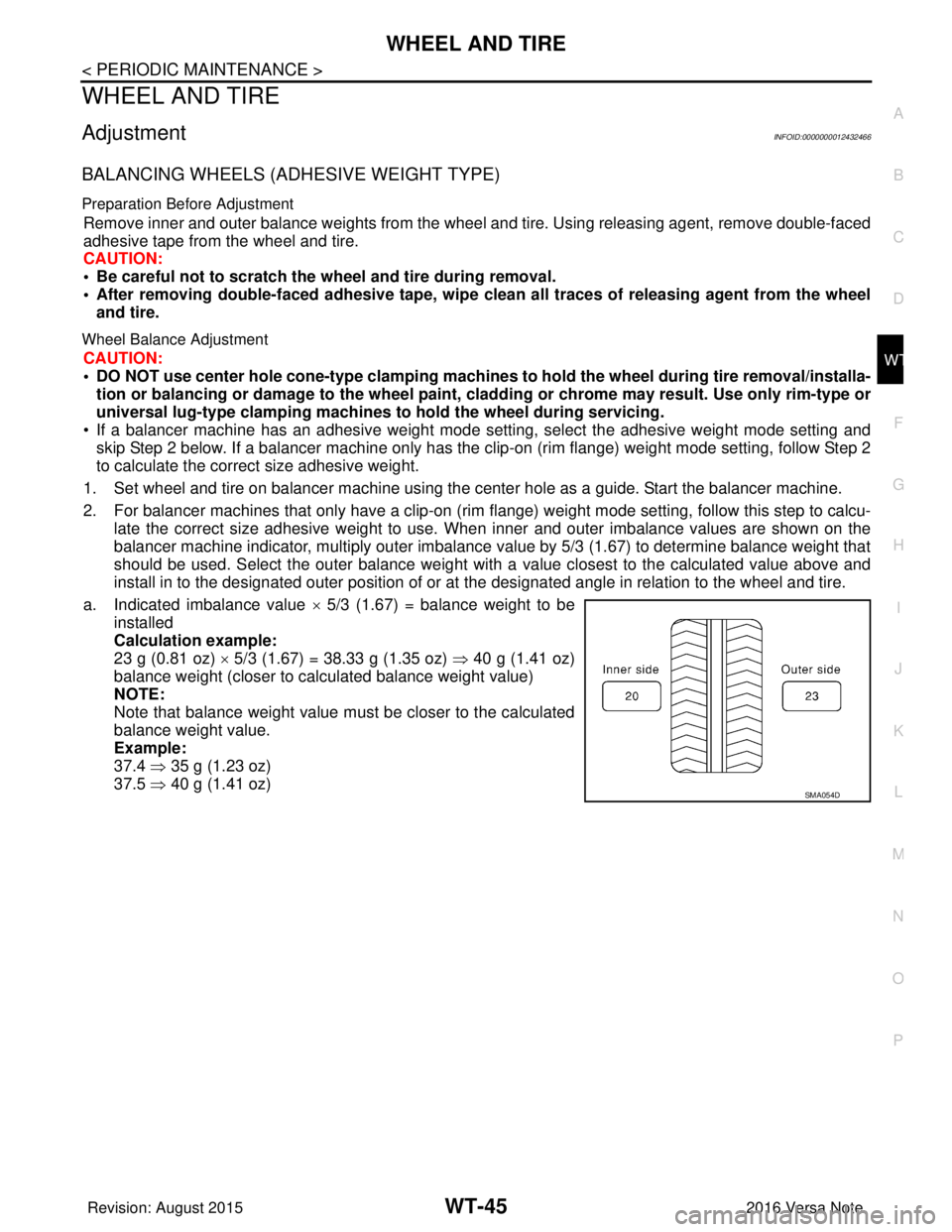
a. Indicated imbalance value × 5/3 (1.67) = balance weight to be
installed
Calculation example:
23 g (0.81 oz) × 5/3 (1.67) = 38.33 g (1.35 oz) ⇒ 40 g (1.41 oz)
balance weight (closer to calculated balance weight value)
NOTE:
Note that balance weight value must be closer to the calculated
balance weight value.
Example:
37.4 ⇒ 35 g (1.23 oz)
37.5 ⇒ 40 g (1.41 oz)
SMA054D
Revision: August 2015 2016 Versa Note
cardiagn.com
Page 2789 of 3641
WT-46
< PERIODIC MAINTENANCE >
WHEEL AND TIRE
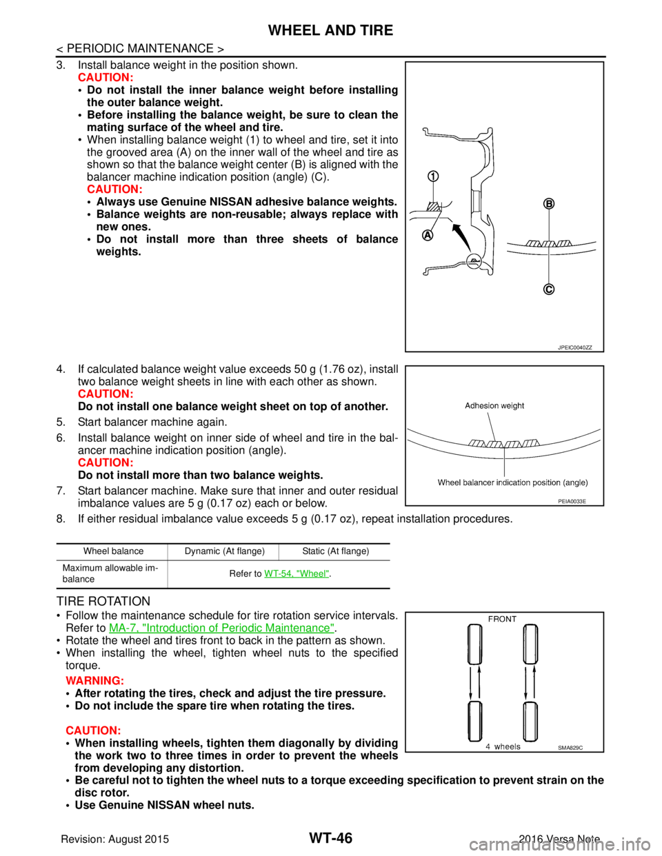
3. Install balance weight in the position shown.CAUTION:
• Do not install the inner bala nce weight before installing
the outer balance weight.
• Before installing the balance weight, be sure to clean the mating surface of the wheel and tire.
• When installing balance weight (1) to wheel and tire, set it into the grooved area (A) on the inner wall of the wheel and tire as
shown so that the balance weight center (B) is aligned with the
balancer machine indication position (angle) (C).
CAUTION:
• Always use Genuine NISSAN adhesive balance weights.
• Balance weights are non-reusable; always replace withnew ones.
• Do not install more than three sheets of balance weights.
4. If calculated balance weight value exceeds 50 g (1.76 oz), install two balance weight sheets in line with each other as shown.
CAUTION:
Do not install one balance weight sheet on top of another.
5. Start balancer machine again.
6. Install balance weight on inner side of wheel and tire in the bal- ancer machine indication position (angle).
CAUTION:
Do not install more than two balance weights.
7. Start balancer machine. Make sure that inner and outer residual imbalance values are 5 g (0.17 oz) each or below.
8. If either residual imbalance value exceeds 5 g (0.17 oz), repeat installation procedures.
TIRE ROTATION
• Follow the maintenance schedule for tire rotation service intervals.
Refer to MA-7, "
Introduction of Periodic Maintenance".
• Rotate the wheel and tires front to back in the pattern as shown.
• When installing the wheel, tighten wheel nuts to the specified torque.
WARNING:
• After rotating the tires, check and adjust the tire pressure.
• Do not include the spare tire when rotating the tires.
CAUTION:
• When installing wheels, tighten them diagonally by dividing
the work two to three times in order to prevent the wheels
from developing any distortion.
• Be careful not to tighten the wh eel nuts to a torque exceeding speci fication to prevent strain on the
disc rotor.
• Use Genuine NISSAN wheel nuts.
JPEIC0040ZZ
Wheel balance Dynamic (At flange) Static (At flange)
Maximum allowable im-
balance Refer to WT-54, "
Wheel".
PEIA0033E
SMA829C
Revision: August 2015
2016 Versa Note
cardiagn.com
Page 2790 of 3641

WHEEL AND TIREWT-47
< PERIODIC MAINTENANCE >
C
DF
G H
I
J
K L
M A
B
WT
N
O P
• Perform the ID registration after tire rotation. Refer to WT-22, "Work Procedure".
Wheel nut tightening
torque
:
WT-48, "
Exploded View"
Revision: August 2015 2016 Versa Note
cardiagn.com