2016 NISSAN NOTE wheel
[x] Cancel search: wheelPage 2351 of 3641

MA-36
< PERIODIC MAINTENANCE >
CHASSIS AND BODY MAINTENANCE
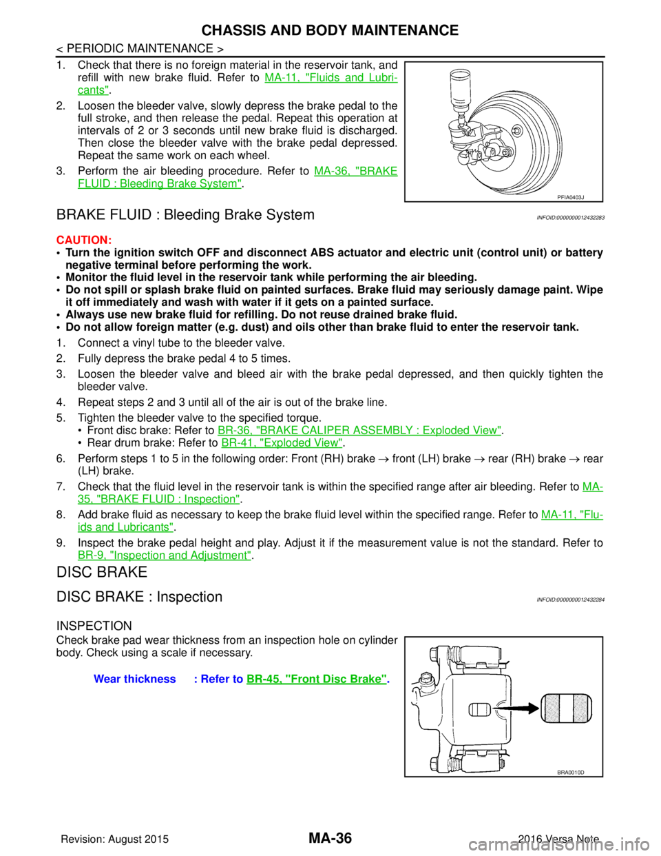
1. Check that there is no foreign material in the reservoir tank, andrefill with new brake fluid. Refer to MA-11, "
Fluids and Lubri-
cants".
2. Loosen the bleeder valve, slowly depress the brake pedal to the full stroke, and then release the pedal. Repeat this operation at
intervals of 2 or 3 seconds until new brake fluid is discharged.
Then close the bleeder valve with the brake pedal depressed.
Repeat the same work on each wheel.
3. Perform the air bleeding procedure. Refer to MA-36, "
BRAKE
FLUID : Bleeding Brake System".
BRAKE FLUID : Bleeding Brake SystemINFOID:0000000012432283
CAUTION:
• Turn the ignition switch OFF and disconnect ABS act uator and electric unit (control unit) or battery
negative terminal before performing the work.
• Monitor the fluid level in the reservoir tank while performing the air bleeding.
• Do not spill or splash brake fluid on painted su rfaces. Brake fluid may seriously damage paint. Wipe
it off immediately and wash with wa ter if it gets on a painted surface.
• Always use new brake fluid for refilling. Do not reuse drained brake fluid.
• Do not allow foreign matter (e.g. dust) and oils other than brake fluid to enter the reservoir tank.
1. Connect a vinyl tube to the bleeder valve.
2. Fully depress the brake pedal 4 to 5 times.
3. Loosen the bleeder valve and bleed air with the br ake pedal depressed, and then quickly tighten the
bleeder valve.
4. Repeat steps 2 and 3 until all of the air is out of the brake line.
5. Tighten the bleeder valve to the specified torque. • Front disc brake: Refer to BR-36, "
BRAKE CALIPER ASSEMBLY : Exploded View".
• Rear drum brake: Refer to BR-41, "
Exploded View".
6. Perform steps 1 to 5 in the following order: Front (RH) brake → front (LH) brake → rear (RH) brake → rear
(LH) brake.
7. Check that the fluid level in the reservoir tank is within the specified range after air bleeding. Refer to MA-
35, "BRAKE FLUID : Inspection".
8. Add brake fluid as necessary to keep the brake fluid level within the specified range. Refer to MA-11, "
Flu-
ids and Lubricants".
9. Inspect the brake pedal height and play. Adjust it if the measurement value is not the standard. Refer to
BR-9, "
Inspection and Adjustment".
DISC BRAKE
DISC BRAKE : InspectionINFOID:0000000012432284
INSPECTION
Check brake pad wear thickness from an inspection hole on cylinder
body. Check using a scale if necessary.
PFIA0403J
Wear thickness : Refer to BR-45, "Front Disc Brake".
BRA0010D
Revision: August 2015 2016 Versa Note
cardiagn.com
Page 2352 of 3641

CHASSIS AND BODY MAINTENANCEMA-37
< PERIODIC MAINTENANCE >
C
DE
F
G H
I
J
K L
M B
MA
N
O A
DISC BRAKE : Brake BurnishingINFOID:0000000012432285
BRAKE BURNISHING
Burnish contact surfaces between disc brake rotor and brake pads according to the following procedure after
refinishing disc brake rotors, replacing disc brake rotors,
replacing brake pads, or if a soft pedal occurs at very
low mileage:
CAUTION:
• Be careful of vehicle speed because the brake peda l does not operate firmly/securely until pads and
disc brake rotor are securely seated.
• Only perform this procedure under safe road and traffic conditions. Use extreme caution.
1. Drive vehicle on straight, flat road.
2. Depress brake pedal with the power to stop vehicle within 3 to 5 seconds until the vehicle stops.
3. Drive without depressing brake pedal for a few minutes to cool the brakes.
4. Repeat steps 1 to 3 until pad and disc brake rotor are securely seated.
DISC BRAKE : InspectionINFOID:0000000012432286
INSPECTION
Appearance
Check surface of disc brake rotor for uneven wear, cra cks, and serious damage. Replace it if necessary. Refer
to BR-45, "
Front Disc Brake".
Runout
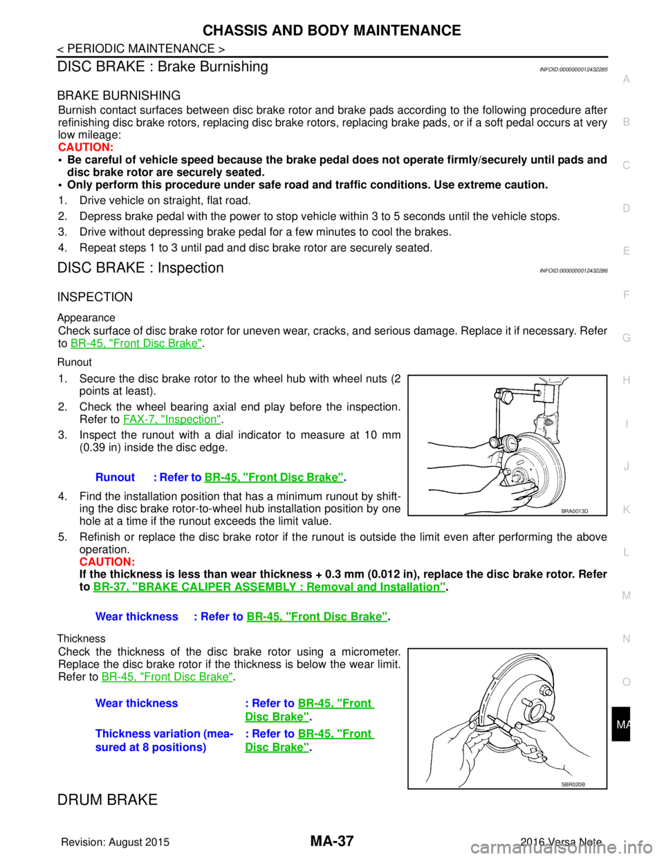
1. Secure the disc brake rotor to the wheel hub with wheel nuts (2
points at least).
2. Check the wheel bearing axial end play before the inspection. Refer to FA X - 7 , "
Inspection".
3. Inspect the runout with a dial indicator to measure at 10 mm (0.39 in) inside the disc edge.
4. Find the installation position that has a minimum runout by shift-
ing the disc brake rotor-to-wheel hub installation position by one
hole at a time if the runout exceeds the limit value.
5. Refinish or replace the disc brake rotor if the runout is outside the limit even after performing the above
operation.
CAUTION:
If the thickness is less than w ear thickness + 0.3 mm (0.012 in), replace the disc brake rotor. Refer
to BR-37, "
BRAKE CALIPER ASSEMBLY : Removal and Installation".
Thickness
Check the thickness of the disc brake rotor using a micrometer.
Replace the disc brake rotor if the thickness is below the wear limit.
Refer to BR-45, "
Front Disc Brake".
DRUM BRAKE
Runout : Refer to BR-45, "Front Disc Brake".
Wear thickness : Refer to BR-45, "
Front Disc Brake".
BRA0013D
Wear thickness: Refer to BR-45, "Front
Disc Brake".
Thickness variation (mea-
sured at 8 positions) : Refer to
BR-45, "
Front
Disc Brake".
SBR020B
Revision: August 2015 2016 Versa Note
cardiagn.com
Page 2353 of 3641

MA-38
< PERIODIC MAINTENANCE >
CHASSIS AND BODY MAINTENANCE
DRUM BRAKE : Inspection
INFOID:0000000012432287
INSPECTION
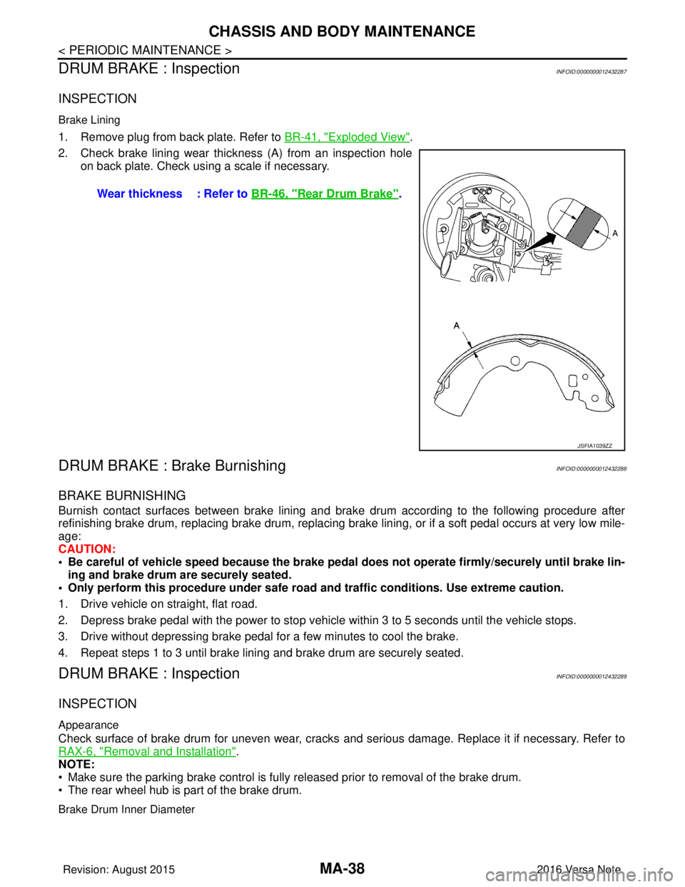
Brake Lining
1. Remove plug from back plate. Refer to BR-41, "Exploded View".
2. Check brake lining wear thickness (A) from an inspection hole on back plate. Check using a scale if necessary.
DRUM BRAKE : Brake BurnishingINFOID:0000000012432288
BRAKE BURNISHING
Burnish contact surfaces between brake lining and brak e drum according to the following procedure after
refinishing brake drum, replacing brake drum, replacing brak e lining, or if a soft pedal occurs at very low mile-
age:
CAUTION:
• Be careful of vehicle speed because the brake peda l does not operate firmly/securely until brake lin-
ing and brake drum are securely seated.
• Only perform this procedure under safe road and traffic conditions. Use extreme caution.
1. Drive vehicle on straight, flat road.
2. Depress brake pedal with the power to stop vehicle within 3 to 5 seconds until the vehicle stops.
3. Drive without depressing brake pedal for a few minutes to cool the brake.
4. Repeat steps 1 to 3 until brake lining and brake drum are securely seated.
DRUM BRAKE : InspectionINFOID:0000000012432289
INSPECTION
Appearance
Check surface of brake drum for uneven wear, cracks and serious damage. Replace it if necessary. Refer to
RAX-6, "
Removal and Installation".
NOTE:
• Make sure the parking brake control is fully released prior to removal of the brake drum.
• The rear wheel hub is part of the brake drum.
Brake Drum Inner Diameter
Wear thickness : Refer to BR-46, "Rear Drum Brake".
JSFIA1039ZZ
Revision: August 2015 2016 Versa Note
cardiagn.com
Page 2354 of 3641

CHASSIS AND BODY MAINTENANCEMA-39
< PERIODIC MAINTENANCE >
C
DE
F
G H
I
J
K L
M B
MA
N
O A
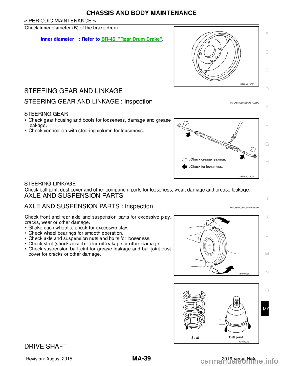
Check inner diameter (B) of the brake drum.
STEERING GEAR AND LINKAGE
STEERING GEAR AND LINKAGE : InspectionINFOID:0000000012432290
STEERING GEAR
• Check gear housing and boots for looseness, damage and grease
leakage.
• Check connection with steering column for looseness.
STEERING LINKAGE
Check ball joint, dust cover and other component parts for looseness, wear, damage and grease leakage.
AXLE AND SUSPENSION PARTS
AXLE AND SUSPENSION PARTS : InspectionINFOID:0000000012432291
Check front and rear axle and suspension parts for excessive play,
cracks, wear or other damage.
• Shake each wheel to check for excessive play.
• Check wheel bearings for smooth operation.
• Check axle and suspension nuts and bolts for looseness.
• Check strut (shock absorber) for oil leakage or other damage.
• Check suspension ball joint for grease leakage and ball joint dust
cover for cracks or other damage.
DRIVE SHAFT
Inner diameter : Refer to BR-46, "Rear Drum Brake".
JPFIA0113ZZ
JPPIA0013GB
SMA525A
SFA392B
Revision: August 2015 2016 Versa Note
cardiagn.com
Page 2370 of 3641
![NISSAN NOTE 2016 Service Repair Manual MWI-12
< SYSTEM DESCRIPTION >[TYPE A]
SYSTEM
SPEEDOMETER
SPEEDOMETER : System DescriptionINFOID:0000000012432545
SYSTEM DIAGRAM
DESCRIPTION
The ABS actuator and electric unit (control unit) receives e NISSAN NOTE 2016 Service Repair Manual MWI-12
< SYSTEM DESCRIPTION >[TYPE A]
SYSTEM
SPEEDOMETER
SPEEDOMETER : System DescriptionINFOID:0000000012432545
SYSTEM DIAGRAM
DESCRIPTION
The ABS actuator and electric unit (control unit) receives e](/manual-img/5/57363/w960_57363-2369.png)
MWI-12
< SYSTEM DESCRIPTION >[TYPE A]
SYSTEM
SPEEDOMETER
SPEEDOMETER : System DescriptionINFOID:0000000012432545
SYSTEM DIAGRAM
DESCRIPTION
The ABS actuator and electric unit (control unit) receives each wheel speed sensor signal and provides a vehi-
cle speed signal to the combination meter via CAN communication.
TACHOMETER
TACHOMETER : System DescriptionINFOID:0000000012432546
SYSTEM DIAGRAM
DESCRIPTION
The crank position sensor sends a crankshaft positi
on signal to the ECM. The ECM provides an engine speed
signal to the combination meter via CAN communication lines. The tachometer indicates engine speed in rev-
olutions per minute (rpm).
SHIFT POSITION INDICATOR
Warning lamp/indicator lamp ABS warning lamp
The lamp turns ON by suspending communication.
Slip indicator lamp
Malfunction indicator lamp (MIL)
VDC OFF indicator lamp
EPS warning lamp
Brake warning lamp
High beam indicator lamp
The lamp turns OFF by suspending communication.
Turn signal indicator lamp
Door warning lamp
Light indicator lamp
Engine oil pressure warning lamp
O/D OFF indicator lamp
Function
Specifications
AWNIA2379GB
JSNIA2462GB
Revision: August 2015 2016 Versa Note
cardiagn.com
Page 2416 of 3641
![NISSAN NOTE 2016 Service Repair Manual MWI-58
< SYSTEM DESCRIPTION >[TYPE B]
COMPONENT PARTS
SYSTEM DESCRIPTION
COMPONENT PARTS
METER SYSTEM
METER SYSTEM : Component Parts LocationINFOID:0000000012432599
A. Steering wheel
B. Combination me NISSAN NOTE 2016 Service Repair Manual MWI-58
< SYSTEM DESCRIPTION >[TYPE B]
COMPONENT PARTS
SYSTEM DESCRIPTION
COMPONENT PARTS
METER SYSTEM
METER SYSTEM : Component Parts LocationINFOID:0000000012432599
A. Steering wheel
B. Combination me](/manual-img/5/57363/w960_57363-2415.png)
MWI-58
< SYSTEM DESCRIPTION >[TYPE B]
COMPONENT PARTS
SYSTEM DESCRIPTION
COMPONENT PARTS
METER SYSTEM
METER SYSTEM : Component Parts LocationINFOID:0000000012432599
A. Steering wheel
B. Combination meter C. View with rear lower seat cushion pad
and inspection hole cover removed.
No. Component Function
1. Parking brake switch Transmits the parking brake switch signal to the combination meter.
2. ABS actuator and electric unit (control unit) Transmits the vehicle speed signal to the combination meter via CAN communica-
tion.
Refer to BRC-7, "
Component Parts Location" for detailed installation location.
ALNIA1658GB
Revision: August 2015
2016 Versa Note
cardiagn.com
Page 2417 of 3641
![NISSAN NOTE 2016 Service Repair Manual MWI
COMPONENT PARTSMWI-59
< SYSTEM DESCRIPTION > [TYPE B]
C
D
E
F
G H
I
J
K L
M B A
O P
METER SYSTEM : Combination MeterINFOID:0000000012432600
The combination meter controls the following items a cco NISSAN NOTE 2016 Service Repair Manual MWI
COMPONENT PARTSMWI-59
< SYSTEM DESCRIPTION > [TYPE B]
C
D
E
F
G H
I
J
K L
M B A
O P
METER SYSTEM : Combination MeterINFOID:0000000012432600
The combination meter controls the following items a cco](/manual-img/5/57363/w960_57363-2416.png)
MWI
COMPONENT PARTSMWI-59
< SYSTEM DESCRIPTION > [TYPE B]
C
D
E
F
G H
I
J
K L
M B A
O P
METER SYSTEM : Combination MeterINFOID:0000000012432600
The combination meter controls the following items a ccording to the signals received from each unit via CAN
communication and the signals from switches and sensors:
• Measuring instruments
• Indicator lamps
• Warning lamps
• Meter illumination control
• Information display
ARRANGEMENT OF COMBINATION METER
3. Washer fluid level switch Transmits the washer fluid level switch signal to the combination meter (for Cana-
da).
Refer to
WW-6, "
Component Parts Location" for detailed installation location.
4. Engine oil pressure sensor Transmits the engine oil pressure sensor signal to the ECM.
Refer to
EM-93, "
Exploded View" for detailed installation location.
5. Ambient sensor Transmits the ambient sensor signal to the combination meter.
6. TCM Transmits the shift position signal to the combination meter via CAN communica-
tion (with CVT).
Refer to
TM-61, "
CVT CONTROL SYSTEM : Component Parts Location" for de-
tailed installation location.
7. ECM Transmits the following signals to the combination meter via CAN communication:
• Engine speed signal
• Engine coolant temperature signal
• Fuel consumption monitor signal
• Engine oil pressure sensor signal
Refer to
EC-14, "
ENGINE CONTROL SYSTEM : ComponentPartsLocation" for
detailed installation location.
8. BCM Transmits the following signals to the combination meter via CAN communication:
• Door switch signal
• Buzzer signal
Refer to
BCS-6, "
BODY CONTROL SYSTEM : Component Parts Location" (with
Intelligent Key system) or BCS-77, "
BODY CONTROL SYSTEM : Component
Parts Location" (without Intelligent Key system) for detailed installation location.
9. Steering wheel audio control switches
(meter control switch) Transmits the meter control switch signal to the combination meter.
10. Combination meter Refer to MWI-59, "
METER SYSTEM : Combination Meter".
11 . Fuel level sensor unit and fuel pump (fuel
level sensor) Transmits the fuel level sensor signal to the combination meter.
No.
Component Function
AWNIA3630ZZ
Revision: August 2015 2016 Versa Note
cardiagn.com
Page 2421 of 3641
![NISSAN NOTE 2016 Service Repair Manual MWI
SYSTEMMWI-63
< SYSTEM DESCRIPTION > [TYPE B]
C
D
E
F
G H
I
J
K L
M B A
O P
SPEEDOMETER
SPEEDOMETER : System DescriptionINFOID:0000000012432603
SYSTEM DIAGRAM
DESCRIPTION
The ABS actuator and elect NISSAN NOTE 2016 Service Repair Manual MWI
SYSTEMMWI-63
< SYSTEM DESCRIPTION > [TYPE B]
C
D
E
F
G H
I
J
K L
M B A
O P
SPEEDOMETER
SPEEDOMETER : System DescriptionINFOID:0000000012432603
SYSTEM DIAGRAM
DESCRIPTION
The ABS actuator and elect](/manual-img/5/57363/w960_57363-2420.png)
MWI
SYSTEMMWI-63
< SYSTEM DESCRIPTION > [TYPE B]
C
D
E
F
G H
I
J
K L
M B A
O P
SPEEDOMETER
SPEEDOMETER : System DescriptionINFOID:0000000012432603
SYSTEM DIAGRAM
DESCRIPTION
The ABS actuator and electric unit (control unit) receives each wheel speed sensor signal and provides a vehi-
cle speed signal to the combination meter via CAN communication.
TACHOMETER
Information display Trip com-
puterCurrent fuel consump-
tion
• When reception time of an abnormal signal is 2 seconds or
less, the last received datum is used for calculation to indi-
cate the result.
• When reception time of an abnormal signal is more than two seconds, the last result calculated during normal condition is
indicated.
Average fuel consump-
tion
Distance to empty
Odo/trip meter An indicated value is maintained at communications blackout.
Buzzer The buzzer turns OFF by suspending communication.
Warning lamp/indicator lamp ABS warning lamp
The lamp turns ON by suspending communication.
Slip indicator lamp
Malfunction indicator lamp (MIL)
VDC OFF indicator lamp
EPS warning lamp
Brake warning lamp
High beam indicator lamp
The lamp turns OFF by suspending communication.
Turn signal indicator lamp
Door warning lamp
Light indicator lamp
Engine oil pressure warning lamp
High water temperature warning
lamp
Key warning lamp
O/D OFF indicator lamp
Shift P warning lamp
Engine start operation indicator lamp
Function
Specifications
AWNIA2379GB
Revision: August 2015 2016 Versa Note
cardiagn.com