2016 NISSAN NOTE length
[x] Cancel search: lengthPage 1553 of 3641
![NISSAN NOTE 2016 Service Repair Manual EC-426
< DTC/CIRCUIT DIAGNOSIS >[HR16DE]
P219A AIR FUEL RATIO
P219A AIR FUEL RATIO
DTC LogicINFOID:0000000012741312
DTC DETECTION LOGIC
NOTE:
•
If DTC P219A is displayed with other DTC, first perfo NISSAN NOTE 2016 Service Repair Manual EC-426
< DTC/CIRCUIT DIAGNOSIS >[HR16DE]
P219A AIR FUEL RATIO
P219A AIR FUEL RATIO
DTC LogicINFOID:0000000012741312
DTC DETECTION LOGIC
NOTE:
•
If DTC P219A is displayed with other DTC, first perfo](/manual-img/5/57363/w960_57363-1552.png)
EC-426
< DTC/CIRCUIT DIAGNOSIS >[HR16DE]
P219A AIR FUEL RATIO
P219A AIR FUEL RATIO
DTC LogicINFOID:0000000012741312
DTC DETECTION LOGIC
NOTE:
•
If DTC P219A is displayed with other DTC, first perform the trouble diagnosis for the other DTC.
Refer to EC-87, "
DTCIndex".
• If DTC P219A is displayed with DTC P219C, P219D, P219E or P219F , perform the trouble diagnosis
for DTC P219C, P219D, P219E or P219F. Refer to EC-87, "
DTCIndex".
DTC CONFIRMATION PROCEDURE
1.PRECONDITIONING-1
If DTC Confirmation Procedure has been previously conducted, always perform the following before conduct-
ing the next test.
1. Turn ignition switch OFF and wait at least 10 seconds.
2. Turn ignition switch ON.
3. Turn ignition switch OFF and wait at least 10 seconds.
NOTE:
Before performing the following procedure, confirm that battery voltage is 11 V or more at idle.
>> GO TO 2.
2.PRECONDITIONING-2
1. Turn ignition switch ON.
2. Clear the mixture ratio self-learning value. Refer to EC-132, "
Description".
Will CONSULT be used?
YES >> GO TO 3.
NO >> GO TO 6.
3.PERFORM DTC CONFIRMATION PROCEDURE-1
1. Turn ignition switch ON.
2. Select “COOLAN TEMP/S” in “DATA MONI TOR” mode of “ENGINE” using CONSULT.
3. Start the engine.
4. Make sure that “COOLAN TEMP/S” indicates more than 80 °C (176° F).
>> GO TO 4.
4.PERFORM DTC CONFIRMATION PROCEDURE-2
With CONSULT
1. Select “SYSTEM 1 DIAG NOSIS B B1” and “SYSTEM 1 DIAGNOSIS A B1” in “DATA MONITOR” mode of
“ENGINE” using CONSULT.
DTC No. CONSULT screen terms
(Trouble diagnosis content) DTC detecting condition
Possible cause
P219A AIR FUEL RATIO IMBAL-
ANCE B1
(Air-fuel ratio imbalance bank
1) ECM detects a lean/rich air fuel ratio state in any
cylinder for a specified length of time. • Fuel injector
• Exhaust gas leaks
• Incorrect fuel pressure
• Mass air flow sensor
• Intake air leaks
• Lack of fuel
• Incorrect PCV hose connection
• Improper spark plug
• Insufficient compression
• The fuel injector circuit is open or
shorted
• ignition coil
• The ignition signal circuit is open or shorted
Revision: August 2015 2016 Versa Note
cardiagn.com
Page 1614 of 3641
![NISSAN NOTE 2016 Service Repair Manual ENGINE COOLANTCO-9
< PERIODIC MAINTENANCE > [HR16DE]
C
D
E
F
G H
I
J
K L
M A
CO
NP
O
2. Connect a suitable hose to the radiator drain plug.
• Use a suitable hose with the dimensions as shown.
3. Ope NISSAN NOTE 2016 Service Repair Manual ENGINE COOLANTCO-9
< PERIODIC MAINTENANCE > [HR16DE]
C
D
E
F
G H
I
J
K L
M A
CO
NP
O
2. Connect a suitable hose to the radiator drain plug.
• Use a suitable hose with the dimensions as shown.
3. Ope](/manual-img/5/57363/w960_57363-1613.png)
ENGINE COOLANTCO-9
< PERIODIC MAINTENANCE > [HR16DE]
C
D
E
F
G H
I
J
K L
M A
CO
NP
O
2. Connect a suitable hose to the radiator drain plug.
• Use a suitable hose with the dimensions as shown.
3. Open radiator drain plug (A) at the bottom of radiator, and then remove radiator cap.
(B): Suitable hose
: Front
CAUTION:
• Perform this step when engine is cold.
• Do not spill engine coolant on the drive belt.
4. It is necessary to drain the cylinder block when drai ning all of engine coolant in the system. To drain the
cylinder block, open the water drain plugs on cylinder block. Refer to EM-93, "
Exploded View".
5. Remove reservoir tank if necessary, and drain engine coolant and clean reservoir tank before installing. Refer to CO-13, "
Exploded View".
6. Check drained engine coolant for contaminants such as rust, corrosion or discoloration. If contaminated,
flush the engine cooling system. Refer to CO-11, "
Flushing Cooling System".
RefillingINFOID:0000000012432135
1. Install the radiator drain plug. Install the reservoir tank and cylinder block drain plug, if removed for a total
system drain or for engine removal or repair.
• The radiator must be completely empty of engine coolant and water.
• Apply sealant to the threads of the cylinder block drain plug. Use Genuine High Performance
Thread Sealant or equivalent. Refer to MA-11, "
Fluids and Lubricants".
2. If disconnected, reattach the upper radiator hose at the engine side.
3. Set the vehicle heater controls to the full HOT and heat er ON position. Turn the vehicle ignition ON with
the engine OFF as necessary to activate the heater mode. Diameter (A) : 0.8 mm (0.31 in)
Length (B) : 300 mm (11.81 in)
JPBIA4770ZZ
AWBIA1613ZZ
Radiator drain plug : Refer to CO-13, "Exploded View".
Revision: August 2015
2016 Versa Note
cardiagn.com
Page 1832 of 3641

FRONT DRIVE SHAFT BOOTFAX-15
< REMOVAL AND INSTALLATION >
CEF
G H
I
J
K L
M A
B
FA X
N
O P
WHEEL SIDE : Removal and InstallationINFOID:0000000012431895
REMOVAL
1. Remove the wheel and tire using power tool. Refer to WT-48, "Removal and Installation".
2. Remove the brake caliper torque member bolts, leav ing the brake hose attached. Position the brake cali-
per aside with wire. Refer to BR-37, "
BRAKE CALIPER ASSEMBLY : Removal and Installation".
CAUTION:
Do not depress the brake pedal while the brake caliper is removed.
3. Put alignment marks on the disc brake rotor and on the wheel hub. Remove the disc brake rotor.
CAUTION:
Do not drop the disc brake rotor.
4. Remove the wheel sensor bolt. Position the wheel sensor and the wheel sensor harness aside. Refer to
BRC-140, "
FRONT WHEEL SENSOR : Removal and Installation".
5. Remove the cotter pin from the drive shaft.
6. Hold the wheel hub using Tool. Loosen the wheel hub lock nut.
7. Using a piece of wood and a suitable tool, tap on the wheel hub lock nut to disengage the drive shaft from the wheel hub.
CAUTION:
• Do not place the drive shaft joint at an extreme angle. Also be careful not to overextend slide
joint.
• Do not allow the drive shaft to hang down without support.
NOTE:
Use a suitable puller if the drive shaft cannot be separated from the wheel hub even after performing the
above procedure.
8. Remove the wheel hub lock nut.
9. Remove the nut and bolt from the lower ball joint. Disconnect the steering knuckle from the transverse
link.
10. Remove the drive shaft from the wheel hub.
11. Remove the boot bands.
12. Separate the boot from the joint sub-assembly.
13. Screw a suitable tool (A) into the joint sub-assembly screw part to a length of 30 mm (1.18 in) or more. Support the drive shaft
with one hand and pull out the joint sub-assembly from the shaft.
CAUTION:
• Align the suitable tool an d the drive shaft. Remove the
joint sub-assembly by pull ing firmly and uniformly.
• If the joint sub-assembly cannot be pulled out, try after removing the drive shaft from the vehicle. Refer to FA X -
22, "Disassembly and Assembly".
14. Remove the circular clip (1) from the shaft.
15. Remove the outer boot from the shaft. Tool number : KV4010104000 ( — )
JPDIF0258ZZ
JPDIF0007ZZ
Revision: August 2015
2016 Versa Note
cardiagn.com
Page 1834 of 3641
FRONT DRIVE SHAFT BOOTFAX-17
< REMOVAL AND INSTALLATION >
CEF
G H
I
J
K L
M A
B
FA X
N
O P
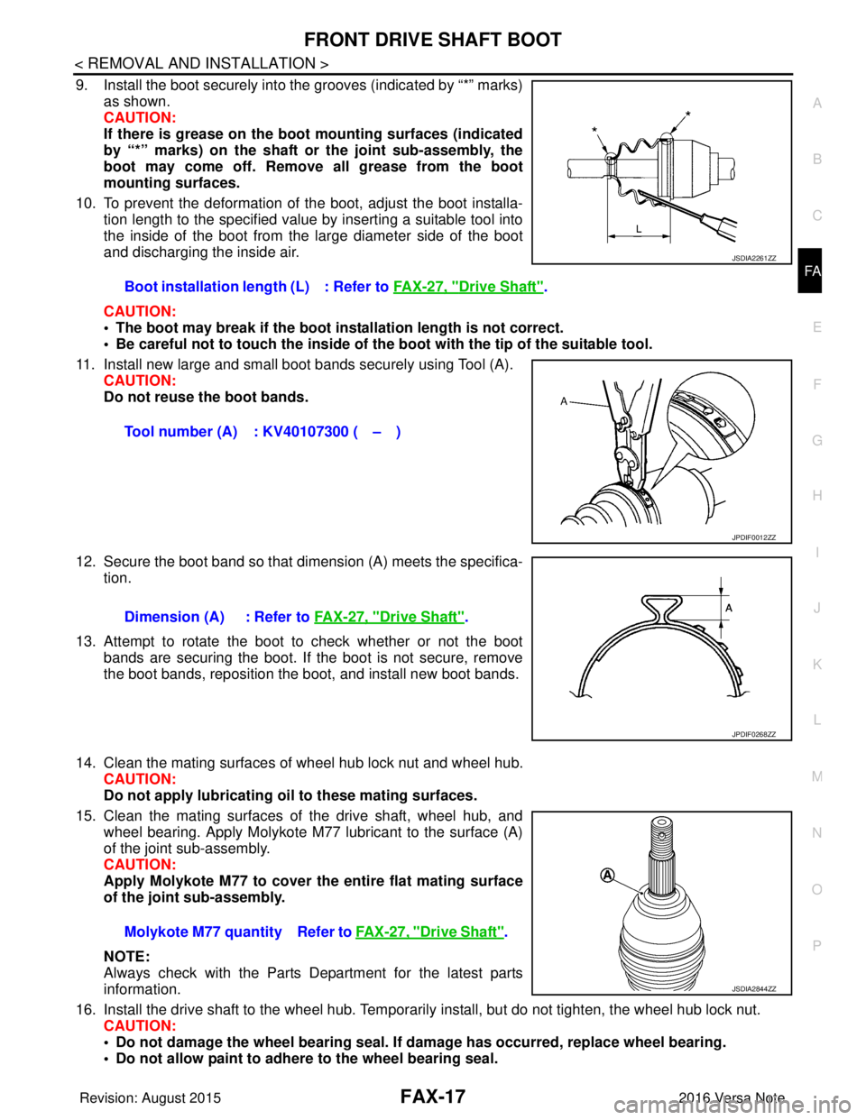
9. Install the boot securely into the grooves (indicated by “*” marks) as shown.
CAUTION:
If there is grease on the bo ot mounting surfaces (indicated
by “*” marks) on the shaft or the joint sub-assembly, the
boot may come off. Remo ve all grease from the boot
mounting surfaces.
10. To prevent the deformation of the boot, adjust the boot installa- tion length to the specified value by inserting a suitable tool into
the inside of the boot from the large diameter side of the boot
and discharging the inside air.
CAUTION:
• The boot may break if the boot in stallation length is not correct.
• Be careful not to touch the inside of the boot with the tip of the suitable tool.
11. Install new large and small boot bands securely using Tool (A). CAUTION:
Do not reuse the boot bands.
12. Secure the boot band so that dimension (A) meets the specifica- tion.
13. Attempt to rotate the boot to check whether or not the boot bands are securing the boot. If the boot is not secure, remove
the boot bands, reposition the boot, and install new boot bands.
14. Clean the mating surfaces of wheel hub lock nut and wheel hub. CAUTION:
Do not apply lubricating oil to these mating surfaces.
15. Clean the mating surfaces of the drive shaft, wheel hub, and wheel bearing. Apply Molykote M77 lubricant to the surface (A)
of the joint sub-assembly.
CAUTION:
Apply Molykote M77 to cover the entire flat mating surface
of the joint sub-assembly.
NOTE:
Always check with the Parts Department for the latest parts
information.
16. Install the drive shaft to the wheel hub. Temporaril y install, but do not tighten, the wheel hub lock nut.
CAUTION:
• Do not damage the wheel bearing seal. If damage has occurred, replace wheel bearing.
• Do not allow paint to adhere to the wheel bearing seal.
Boot installation length (L) : Refer to
FAX-27, "
Drive Shaft".
Tool number (A) : KV40107300 ( – )
JSDIA2261ZZ
JPDIF0012ZZ
Dimension (A) : Refer to FAX-27, "Drive Shaft".
JPDIF0268ZZ
Molykote M77 quantity Refer to FAX-27, "Drive Shaft".
JSDIA2844ZZ
Revision: August 2015 2016 Versa Note
cardiagn.com
Page 1839 of 3641
FAX-22
< UNIT DISASSEMBLY AND ASSEMBLY >
FRONT DRIVE SHAFT
Disassembly and Assembly
INFOID:0000000012431901
DISASSEMBLY (WHEEL SIDE)
1. Mount the drive shaft in a vise. CAUTION:
When mounting the drive shaft in a vise, always use aluminum or copper plates between the vise
and the drive shaft.
2. Remove the boot bands and slide the boot back.
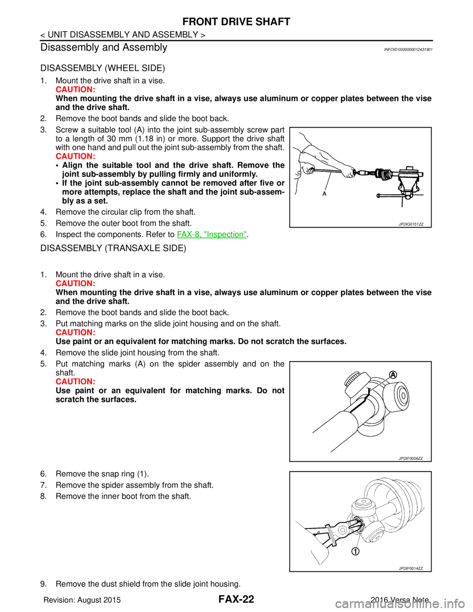
3. Screw a suitable tool (A) into the joint sub-assembly screw part to a length of 30 mm (1.18 in) or more. Support the drive shaft
with one hand and pull out the joint sub-assembly from the shaft.
CAUTION:
• Align the suitable tool and the drive shaft. Remove thejoint sub-assembly by pulli ng firmly and uniformly.
• If the joint sub-assembly cannot be removed after five or more attempts, replace the shaft and the joint sub-assem-
bly as a set.
4. Remove the circular clip from the shaft.
5. Remove the outer boot from the shaft.
6. Inspect the components. Refer to FAX-8, "
Inspection".
DISASSEMBLY (TRANSAXLE SIDE)
1. Mount the drive shaft in a vise. CAUTION:
When mounting the drive shaft in a vise, always use aluminum or copper plates between the vise
and the drive shaft.
2. Remove the boot bands and slide the boot back.
3. Put matching marks on the slide joint housing and on the shaft. CAUTION:
Use paint or an equivalent for matchi ng marks. Do not scratch the surfaces.
4. Remove the slide joint housing from the shaft.
5. Put matching marks (A) on the spider assembly and on the shaft.
CAUTION:
Use paint or an equivalent fo r matching marks. Do not
scratch the surfaces.
6. Remove the snap ring (1).
7. Remove the spider assembly from the shaft.
8. Remove the inner boot from the shaft.
9. Remove the dust shield from the slide joint housing.
JPDIG0151ZZ
JPDIF0006ZZ
JPDIF0014ZZ
Revision: August 2015 2016 Versa Note
cardiagn.com
Page 1841 of 3641
FAX-24
< UNIT DISASSEMBLY AND ASSEMBLY >
FRONT DRIVE SHAFT
Always check with the Parts Department for the latest parts information.
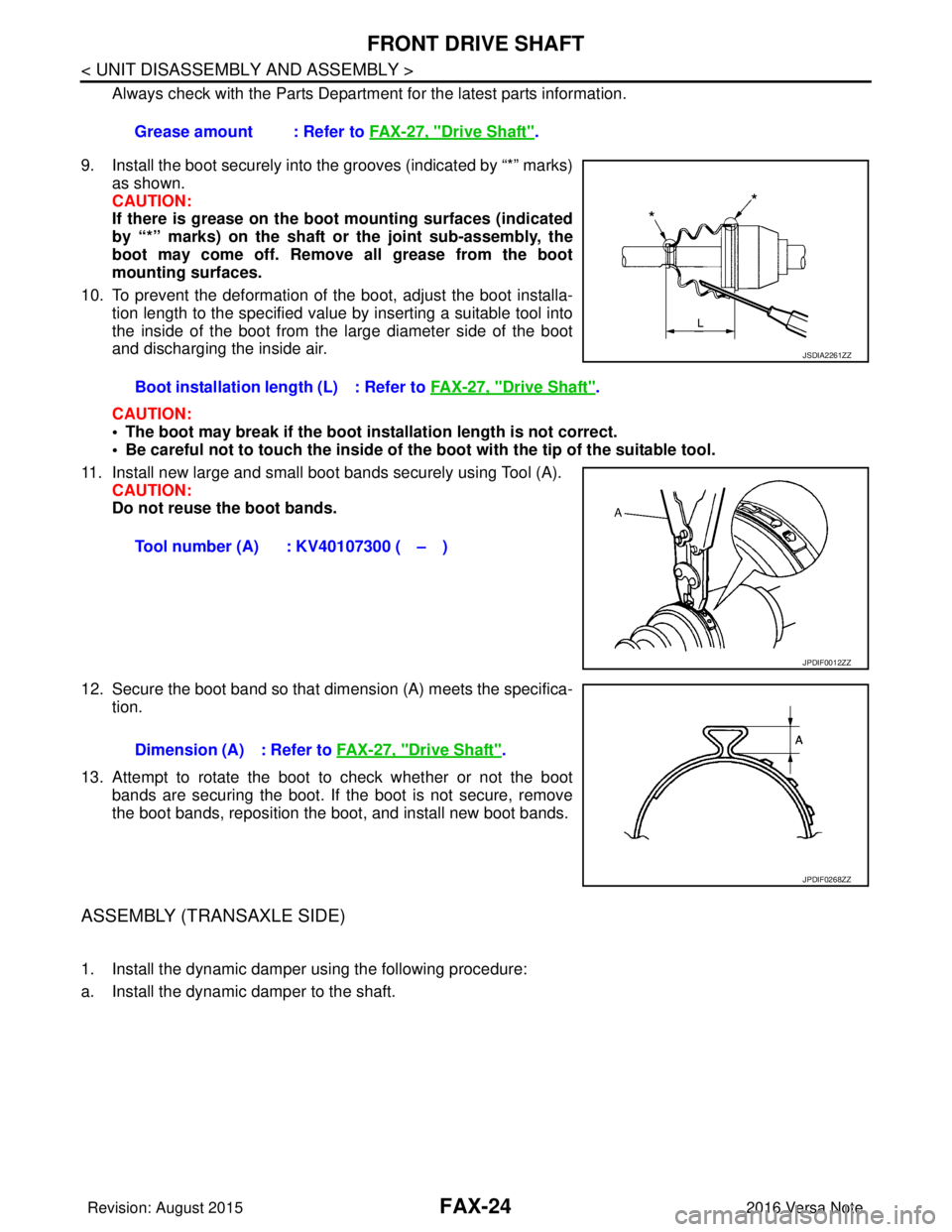
9. Install the boot securely into the grooves (indicated by “*” marks) as shown.
CAUTION:
If there is grease on the boot mounting surfaces (indicated
by “*” marks) on the shaft or the joint sub-assembly, the
boot may come off. Remove all grease from the boot
mounting surfaces.
10. To prevent the deformation of the boot, adjust the boot installa- tion length to the specified value by inserting a suitable tool into
the inside of the boot from the large diameter side of the boot
and discharging the inside air.
CAUTION:
• The boot may break if the boot installation length is not correct.
• Be careful not to touch the inside of the boot with the tip of the suitable tool.
11. Install new large and small boot bands securely using Tool (A). CAUTION:
Do not reuse the boot bands.
12. Secure the boot band so that dimension (A) meets the specifica- tion.
13. Attempt to rotate the boot to check whether or not the boot bands are securing the boot. If the boot is not secure, remove
the boot bands, reposition the boot, and install new boot bands.
ASSEMBLY (TRANSAXLE SIDE)
1. Install the dynamic damper using the following procedure:
a. Install the dynamic damper to the shaft. Grease amount : Refer to
FAX-27, "
Drive Shaft".
Boot installation length (L) : Refer to FAX-27, "
Drive Shaft".
Tool number (A) : KV40107300 ( – )
JSDIA2261ZZ
JPDIF0012ZZ
Dimension (A) : Refer to FAX-27, "Drive Shaft".
JPDIF0268ZZ
Revision: August 2015 2016 Versa Note
cardiagn.com
Page 1843 of 3641
FAX-26
< UNIT DISASSEMBLY AND ASSEMBLY >
FRONT DRIVE SHAFT
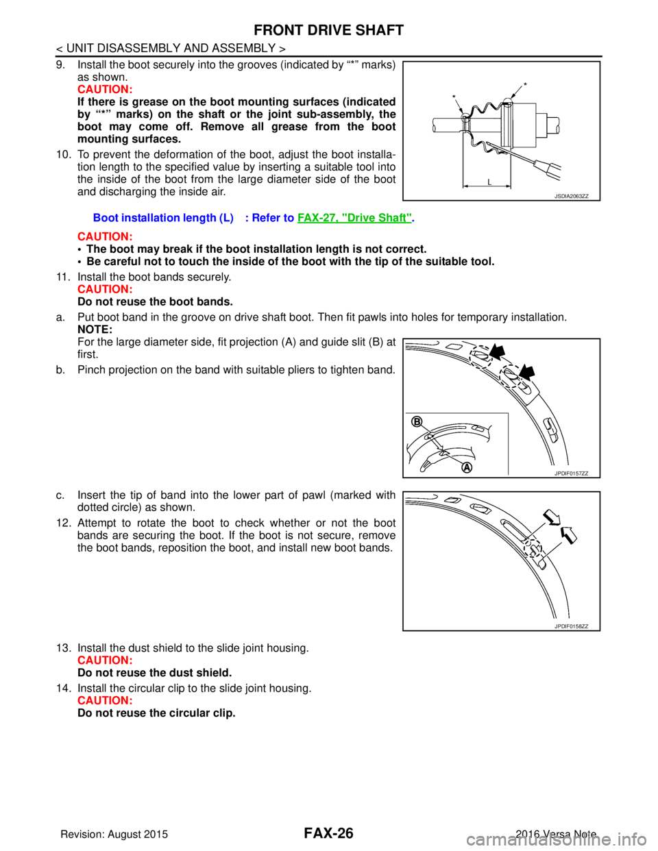
9. Install the boot securely into the grooves (indicated by “*” marks)as shown.
CAUTION:
If there is grease on the boot mounting surfaces (indicated
by “*” marks) on the shaft or the joint sub-assembly, the
boot may come off. Remove all grease from the boot
mounting surfaces.
10. To prevent the deformation of the boot, adjust the boot installa- tion length to the specified value by inserting a suitable tool into
the inside of the boot from the large diameter side of the boot
and discharging the inside air.
CAUTION:
• The boot may break if the boot installation length is not correct.
• Be careful not to touch the inside of the boot with the tip of the suitable tool.
11. Install the boot bands securely. CAUTION:
Do not reuse the boot bands.
a. Put boot band in the groove on drive shaft boot. Then fit pawls into holes for temporary installation. NOTE:
For the large diameter side, fit projection (A) and guide slit (B) at
first.
b. Pinch projection on the band with suitable pliers to tighten band.
c. Insert the tip of band into the lower part of pawl (marked with dotted circle) as shown.
12. Attempt to rotate the boot to check whether or not the boot bands are securing the boot. If the boot is not secure, remove
the boot bands, reposition the boot, and install new boot bands.
13. Install the dust shield to the slide joint housing. CAUTION:
Do not reuse the dust shield.
14. Install the circular clip to the slide joint housing. CAUTION:
Do not reuse the circular clip.Boot installation length (L) : Refer to
FAX-27, "
Drive Shaft".
JSDIA2063ZZ
JPDIF0157ZZ
JPDIF0158ZZ
Revision: August 2015 2016 Versa Note
cardiagn.com
Page 1844 of 3641
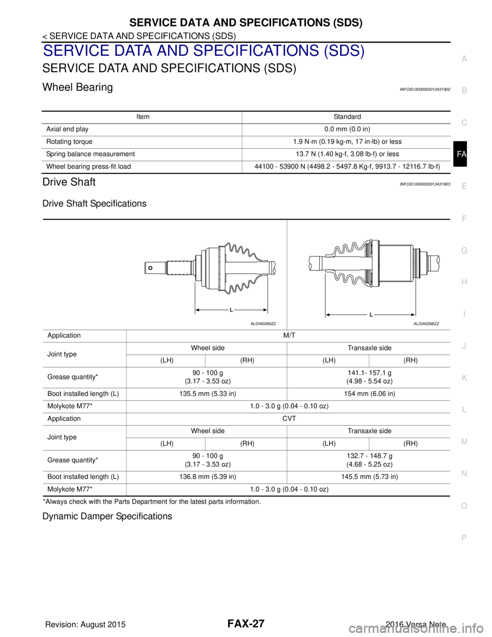
SERVICE DATA AND SPECIFICATIONS (SDS)FAX-27
< SERVICE DATA AND SPECIFICATIONS (SDS)
CEF
G H
I
J
K L
M A
B
FA X
N
O P
SERVICE DATA AND SPECIFICATIONS (SDS)
SERVICE DATA AND SPECIFICATIONS (SDS)
Wheel BearingINFOID:0000000012431902
Drive ShaftINFOID:0000000012431903
Drive Shaft Specifications
*Always check with the Parts Departme nt for the latest parts information.
Dynamic Damper Specifications
Item Standard
Axial end play 0.0 mm (0.0 in)
Rotating torque 1.9 N·m (0.19 kg-m, 17 in-lb) or less
Spring balance measurement 13.7 N (1.40 kg-f, 3.08 lb-f) or less
Wheel bearing press-fit load 44100 - 53900 N (4498.2 - 5497.8 Kg-f, 9913.7 - 12116.7 Ib-f)
Application M/T
Joint type Wheel side
Transaxle side
(LH) (RH) (LH)(RH)
Grease quantity* 90 - 100 g
(3.17 - 3.53 oz) 141.1- 157.1 g
(4.98 - 5.54 oz)
Boot installed length (L) 135.5 mm (5.33 in) 154 mm (6.06 in)
Molykote M77* 1.0 - 3.0 g (0.04 - 0.10 oz)
Application CVT
Joint type Wheel side
Transaxle side
(LH) (RH) (LH)(RH)
Grease quantity* 90 - 100 g
(3.17 - 3.53 oz) 132.7 - 148.7 g
(4.68 - 5.25 oz)
Boot installed length (L) 136.8 mm (5.39 in) 145.5 mm (5.73 in)
Molykote M77* 1.0 - 3.0 g (0.04 - 0.10 oz)
ALDIA0269ZZALDIA0268ZZ
Revision: August 2015 2016 Versa Note
cardiagn.com