2016 NISSAN NOTE length
[x] Cancel search: lengthPage 3040 of 3641
DIAGNOSIS SENSOR UNITSRC-23
< ECU DIAGNOSIS INFORMATION >
C
DE
F
G
I
J
K L
M A
B
SRC
N
O P
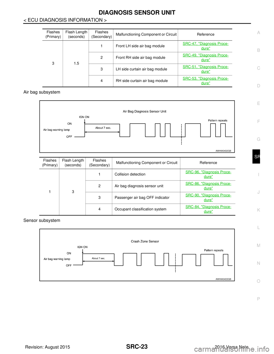
Air bag subsystem
Sensor subsystem
Flashes
(Primary) Flash Length
(seconds) Flashes
(Secondary) Malfunctioning Component or Circuit
Reference
31 .5 1 Front LH side air bag module
SRC-47, "
Diagnosis Proce-
dure"
2 Front RH side air bag moduleSRC-49, "Diagnosis Proce-
dure"
3 LH side curtain air bag module
SRC-51, "Diagnosis Proce-
dure"
4 RH side curtain air bag moduleSRC-53, "Diagnosis Proce-
dure"
AWHIA0432GB
Flashes
(Primary) Flash Length
(seconds) Flashes
(Secondary) Malfunctioning Component or Circuit
Reference
13 1 Collision detection
SRC-96, "
Diagnosis Proce-
dure"
2 Air bag diagnosis sensor unitSRC-86, "Diagnosis Proce-
dure"
3 Passenger air bag OFF indicator
SRC-90, "Diagnosis Proce-
dure"
4 Occupant classification systemSRC-84, "Diagnosis Proce-
dure"
AWHIA0433GB
Revision: August 2015
2016 Versa Note
cardiagn.com
Page 3041 of 3641
SRC-24
< ECU DIAGNOSIS INFORMATION >
DIAGNOSIS SENSOR UNIT
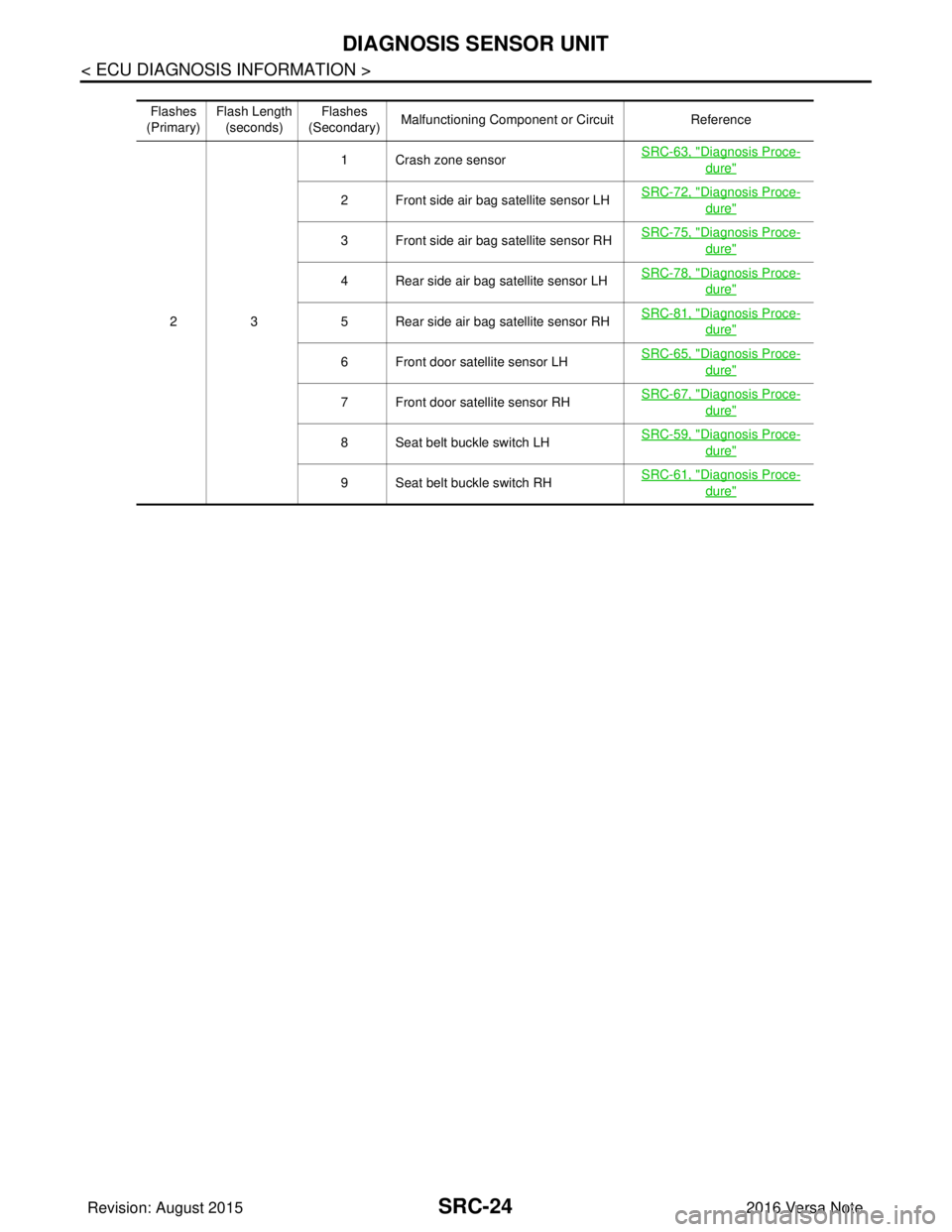
Flashes
(Primary) Flash Length
(seconds) Flashes
(Secondary) Malfunctioning Component or Circuit
Reference
23 1 Crash zone sensor
SRC-63, "
Diagnosis Proce-
dure"
2 Front side air bag satellite sensor LHSRC-72, "Diagnosis Proce-
dure"
3 Front side air bag satellite sensor RH
SRC-75, "Diagnosis Proce-
dure"
4 Rear side air bag satellite sensor LHSRC-78, "Diagnosis Proce-
dure"
5 Rear side air bag satellite sensor RHSRC-81, "Diagnosis Proce-
dure"
6 Front door satellite sensor LH
SRC-65, "Diagnosis Proce-
dure"
7 Front door satellite sensor RHSRC-67, "Diagnosis Proce-
dure"
8 Seat belt buckle switch LHSRC-59, "Diagnosis Proce-
dure"
9 Seat belt buckle switch RH
SRC-61, "Diagnosis Proce-
dure"
Revision: August 2015
2016 Versa Note
cardiagn.com
Page 3222 of 3641

ST-1
STEERING
C
DE
F
H I
J
K L
M
SECTION ST
A
B
ST
N
O P
CONTENTS
STEERING SYSTEM
PRECAUTION ....... ........................................2
PRECAUTIONS .............................................. .....2
Precaution for Supplemental Restraint System
(SRS) "AIR BAG" and "SEAT BELT PRE-TEN-
SIONER" ............................................................. ......
2
Service Notice or Precautions for Steering System
......
2
PREPARATION ............................................3
PREPARATION .............................................. .....3
Special Service Tool ........................................... ......3
Commercial Service Tool ..........................................3
BASIC INSPECTION ....................................5
STEERING WHEEL ........................................ .....5
Inspection ............................................................ ......5
SYMPTOM DIAGNOSIS ...............................7
NOISE, VIBRATION AND HARSHNESS
(NVH) TROUBLESHOOTING ........................ .....
7
NVH Troubleshooting Chart ................................ ......7
REMOVAL AND INSTALLATION ................8
STEERING WHEEL ........................................ .....8
Exploded View .................................................... ......8
Removal and Installation ...........................................8
STEERING COLUMN ..................................... .....9
Exploded View .................................................... ......9
Removal and Installation ...........................................9
Inspection ............................................................ ....10
STEERING SHAFT ...........................................12
Exploded View .........................................................12
Removal and Installation .........................................12
Inspection ................................................................13
STEERING GEAR AND LINKAGE ...................14
Exploded View .........................................................14
Removal and Installation .........................................14
Inspection ................................................................14
UNIT DISASSEMBLY AND ASSEMBLY ....16
STEERING GEAR AND LINKAGE ...................16
Exploded View ..................................................... ....16
Disassembly and Assembly .....................................16
Inspection ................................................................18
SERVICE DATA AND SPECIFICATIONS
(SDS) ............... .......................................... ...
19
SERVICE DATA AND SPECIFICATIONS
(SDS) .................................................................
19
General Specifications ......................................... ....19
Steering Wheel Axial End Play and Play .................19
Steering Wheel Turning Force .................................19
Steering Angle ..................................................... ....19
Steering Column Operating Range .........................19
Rack Stroke ......................................................... ....20
Ball Joint Swing Force .............................................20
Ball Joint Axial End Play ..........................................20
Inner Socket Length ................................................20
Revision: August 2015 2016 Versa Note
cardiagn.com
Page 3232 of 3641
STEERING COLUMNST-11
< REMOVAL AND INSTALLATION >
C
DE
F
H I
J
K L
M A
B
ST
N
O P
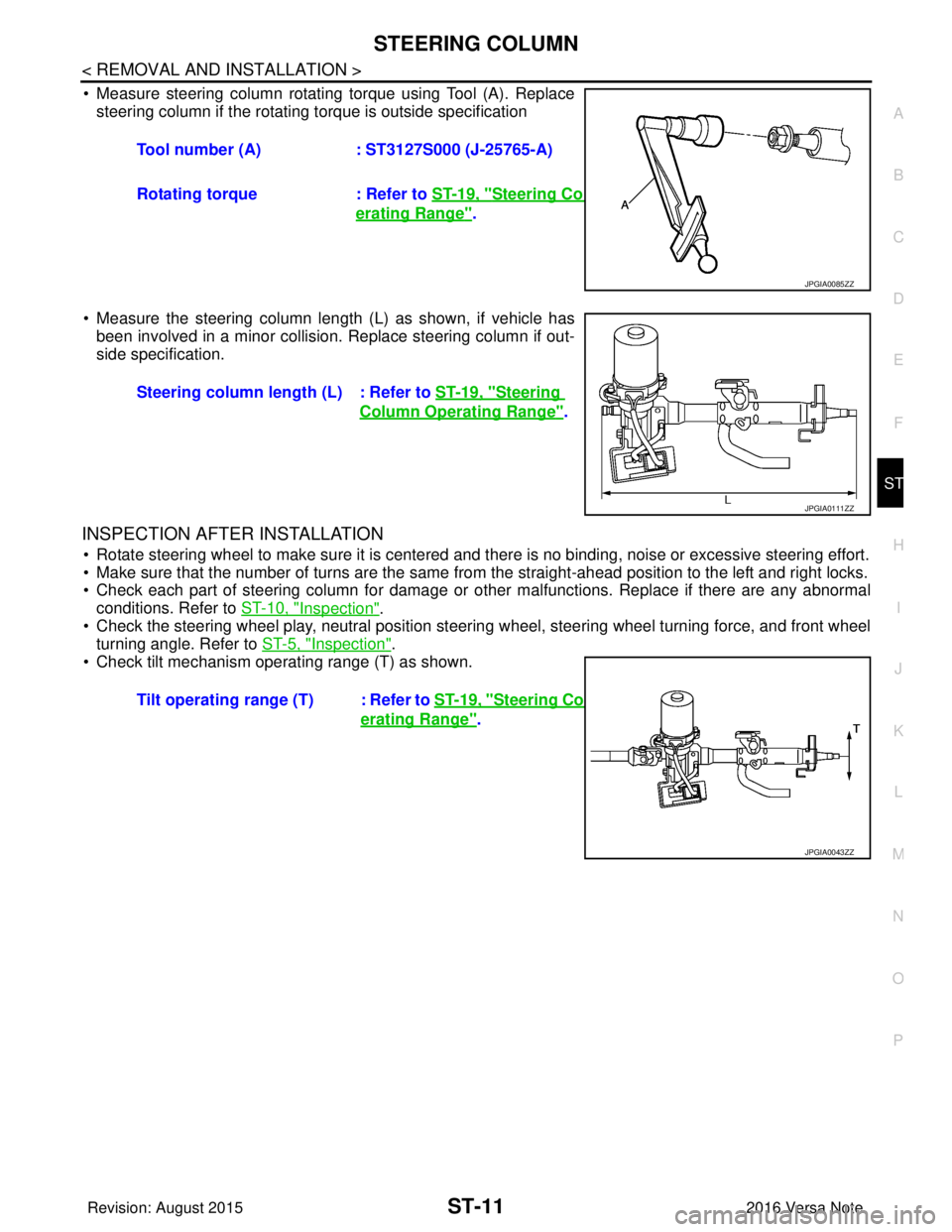
• Measure steering column rotating torque using Tool (A). Replace steering column if the rotating torque is outside specification
• Measure the steering column length (L) as shown, if vehicle has been involved in a minor collision. Replace steering column if out-
side specification.
INSPECTION AFTER INSTALLATION
• Rotate steering wheel to make sure it is centered and there is no binding, noise or excessive steering effort.
• Make sure that the number of turns are the same from the straight-ahead position to the left and right locks.
• Check each part of steering column for damage or other malfunctions. Replace if there are any abnormal
conditions. Refer to ST-10, "
Inspection".
• Check the steering wheel play, neutral position steering wheel, steering wheel turning force, and front wheel turning angle. Refer to ST-5, "
Inspection".
• Check tilt mechanism operating range (T) as shown. Tool number (A)
: ST3127S000 (J-25765-A)
Rotating torque : Refer to ST-19, "
Steering Column Op-
erating Range".
JPGIA0085ZZ
Steering column length (L) : Refer to ST-19, "Steering
Column Operating Range".
JPGIA0111ZZ
Tilt operating range (T) : Refer to ST-19, "Steering Column Op-
erating Range".
JPGIA0043ZZ
Revision: August 2015 2016 Versa Note
cardiagn.com
Page 3238 of 3641
STEERING GEAR AND LINKAGEST-17
< UNIT DISASSEMBLY AND ASSEMBLY >
C
DE
F
H I
J
K L
M A
B
ST
N
O P
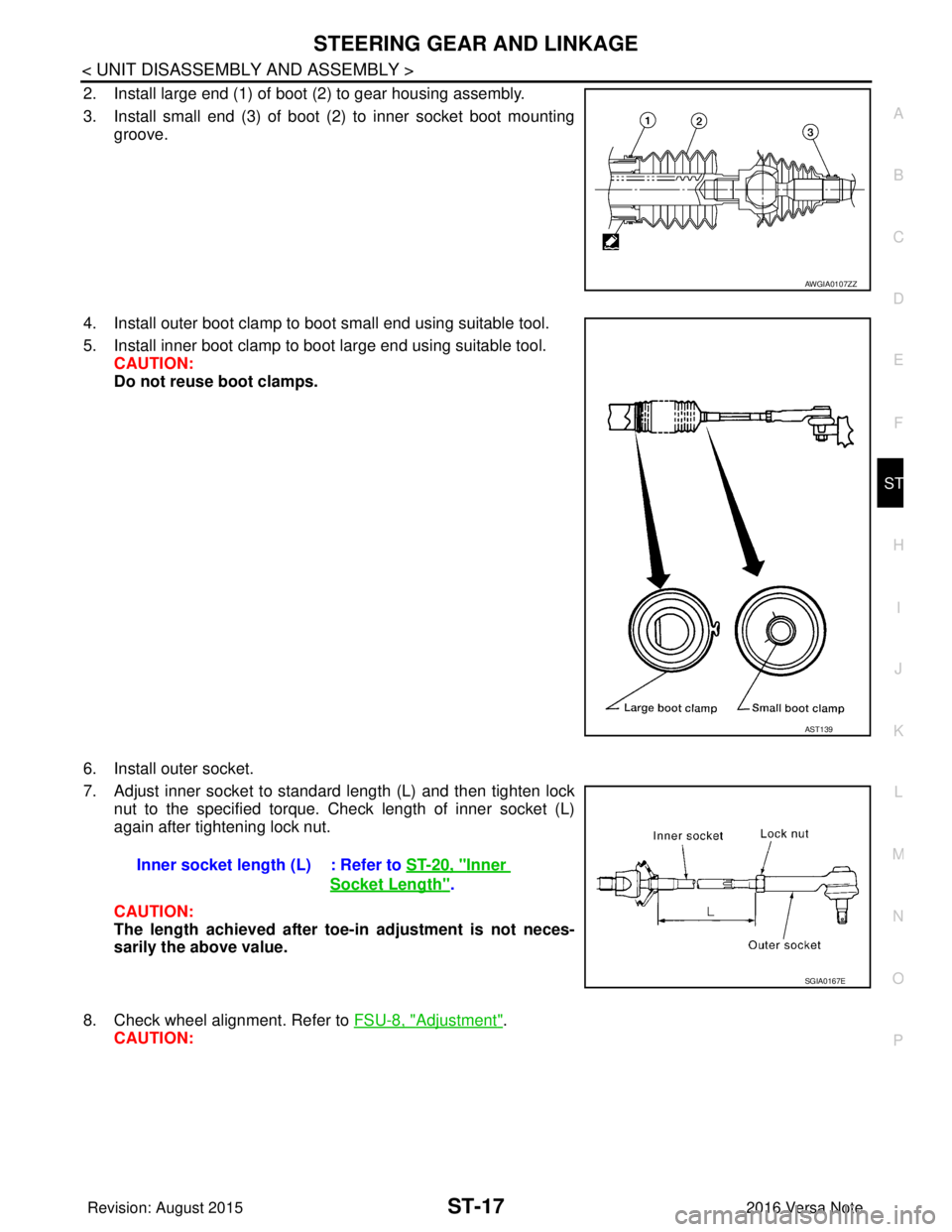
2. Install large end (1) of boot (2) to gear housing assembly.
3. Install small end (3) of boot (2) to inner socket boot mounting groove.
4. Install outer boot clamp to boot small end using suitable tool.
5. Install inner boot clamp to boot large end using suitable tool. CAUTION:
Do not reuse boot clamps.
6. Install outer socket.
7. Adjust inner socket to standard length (L) and then tighten lock nut to the specified torque. Check length of inner socket (L)
again after tightening lock nut.
CAUTION:
The length achieved after toe-in adjustment is not neces-
sarily the above value.
8. Check wheel alignment. Refer to FSU-8, "
Adjustment".
CAUTION:
AWGIA0107ZZ
AST139
Inner socket length (L) : Refer to ST-20, "Inner
Socket Length".
SGIA0167E
Revision: August 2015 2016 Versa Note
cardiagn.com
Page 3240 of 3641
SERVICE DATA AND SPECIFICATIONS (SDS)ST-19
< SERVICE DATA AND SPECIFICATIONS (SDS)
C
DE
F
H I
J
K L
M A
B
ST
N
O P
SERVICE DATA AND SPECIFICATIONS (SDS)
SERVICE DATA AND SPECIFICATIONS (SDS)
General SpecificationsINFOID:0000000012430513
Steering Wheel Axial End Play and PlayINFOID:0000000012430514
Unit: mm (in)
Steering Wheel Turning ForceINFOID:0000000012430515
Unit: N (kg-f, lb-f)
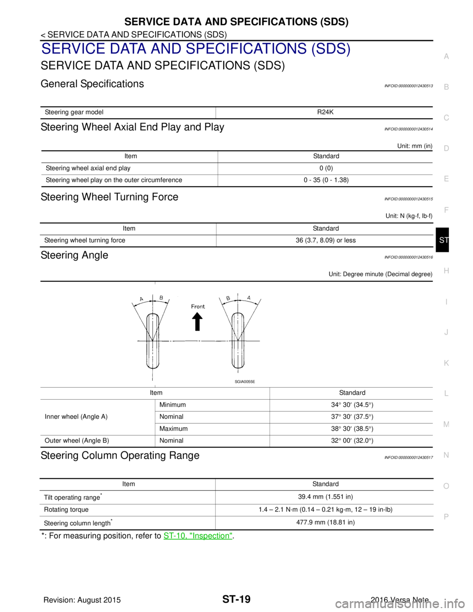
Steering AngleINFOID:0000000012430516
Unit: Degree minute (Decimal degree)
Steering Column Operating RangeINFOID:0000000012430517
*: For measuring position, refer to ST-10, "Inspection".
Steering gear model R24K
ItemStandard
Steering wheel axial end play 0 (0)
Steering wheel play on the outer circumference 0 - 35 (0 - 1.38)
ItemStandard
Steering wheel turning force 36 (3.7, 8.09) or less
ItemStandard
Inner wheel (Angle A) Minimum
34° 30 ′ (34.5° )
Nominal 37° 30 ′ (37.5° )
Maximum 38° 30 ′ (38.5° )
Outer wheel (Angle B) Nominal 32° 00 ′ (32.0° )
SGIA0055E
Item Standard
Tilt operating range
*39.4 mm (1.551 in)
Rotating torque 1.4 – 2.1 N·m (0.14 – 0.21 kg-m, 12 – 19 in-lb)
Steering column length
*477.9 mm (18.81 in)
Revision: August 2015 2016 Versa Note
cardiagn.com
Page 3241 of 3641
ST-20
< SERVICE DATA AND SPECIFICATIONS (SDS)
SERVICE DATA AND SPECIFICATIONS (SDS)
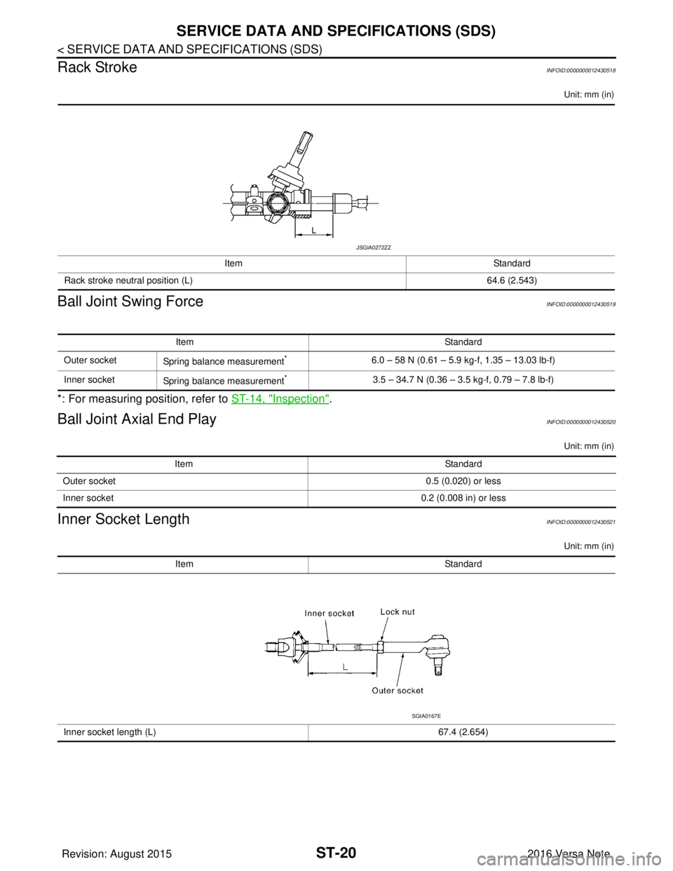
Rack Stroke
INFOID:0000000012430518
Unit: mm (in)
Ball Joint Swing ForceINFOID:0000000012430519
*: For measuring position, refer to ST-14, "Inspection".
Ball Joint Axial End PlayINFOID:0000000012430520
Unit: mm (in)
Inner Socket LengthINFOID:0000000012430521
Unit: mm (in)
Item Standard
Rack stroke neutral position (L) 64.6 (2.543)
JSGIA0272ZZ
ItemStandard
Outer socket Spring balance measurement
*6.0 – 58 N (0.61 – 5.9 kg-f, 1.35 – 13.03 lb-f)
Inner socket Spring balance measurement
*3.5 – 34.7 N (0.36 – 3.5 kg-f, 0.79 – 7.8 lb-f)
Item Standard
Outer socket 0.5 (0.020) or less
Inner socket 0.2 (0.008 in) or less
ItemStandard
Inner socket length (L) 67.4 (2.654)
SGIA0167E
Revision: August 2015 2016 Versa Note
cardiagn.com
Page 3266 of 3641
![NISSAN NOTE 2016 Service Repair Manual TRANSAXLE ASSEMBLYTM-25
< UNIT REMOVAL AND INSTALLATION > [5MT: RS5F91R]
C
EF
G H
I
J
K L
M A
B
TM
N
O P
• Do not reuse self-tapping bolt.
• Tighten transaxle assembly bolts to the specified torqu NISSAN NOTE 2016 Service Repair Manual TRANSAXLE ASSEMBLYTM-25
< UNIT REMOVAL AND INSTALLATION > [5MT: RS5F91R]
C
EF
G H
I
J
K L
M A
B
TM
N
O P
• Do not reuse self-tapping bolt.
• Tighten transaxle assembly bolts to the specified torqu](/manual-img/5/57363/w960_57363-3265.png)
TRANSAXLE ASSEMBLYTM-25
< UNIT REMOVAL AND INSTALLATION > [5MT: RS5F91R]
C
EF
G H
I
J
K L
M A
B
TM
N
O P
• Do not reuse self-tapping bolt.
• Tighten transaxle assembly bolts to the specified torque. The illus- tration is the view from the engine.
InspectionINFOID:0000000012430963
INSPECTION AFTER INSTALLATION
• Check the operation of the control linkage. Refer to TM-21, "Inspection".
• Before starting engine, check oil/fluid levels incl uding engine coolant and engine oil. If less than required
quantity, fill to the specified level. Refer to MA-11, "
Fluids and Lubricants".
• Use procedure below to check for fuel leaks.
• Turn ignition switch ON (with engine stopped). With fuel pressure applied to fuel piping, check for fuel leaks at connection points.
• Start engine. With engine speed increased, check again for fuel leaks at connection points.
• Run engine to check for unusual noise and vibration. NOTE:
If hydraulic pressure inside timing chain tensioner drops after removal and installation, slack in the guide
may generate a pounding noise during and just after engine start. However, this is normal. Noise will stop
after hydraulic pressure rises.
• Warm up engine thoroughly to make sure there is no lea ks of fuel, exhaust gas, or any oils/fluids including
engine oil and engine coolant.
• Bleed air from passages in lines and hoses, such as in cooling system.
• After cooling down engine, again check oil/fluid levels including engine oil and engine coolant. Refill to spec-
ified level, if necessary.
• Summary of the inspection items:
*Power steering fluid, brake fluid, etc.
Bolt symbol
ABC D
Insertion direction Transaxle to
engine Engine to transaxle
Quantity 2321
Bolt length
() mm (in) 55 (2.17)
49 (1.93) 69 (2.72)
Tightening torque
N·m (kg-m, ft-lb) 48.0 (4.9, 35)
JPDIC0813ZZ
Item
Before starting engine Engine runningAfter engine stopped
Engine coolant LevelLeaks Level
Engine oil LevelLeaks Level
Transmission/
transaxle fluid CVT Models
LeaksLevel/Leaks Leaks
M/T Models Level/Leaks LeaksLevel/Leaks
Other oils and fluids* LevelLeaks Level
Fuel LeaksLeaks Leaks
Exhaust gas —Leaks —
Revision: August 2015 2016 Versa Note
cardiagn.com