2016 NISSAN NOTE wheel
[x] Cancel search: wheelPage 1835 of 3641
FAX-18
< REMOVAL AND INSTALLATION >
FRONT DRIVE SHAFT BOOT
• Check each mating surface for water and foreign matter. If there is any water or foreign matter,
clean the mating surface.
17. Install the transverse link to the steering knuckle with the nut and bolt. Refer to FSU-10, "
Exploded View".
18. Hold the wheel hub using a Tool. Tighten the wheel hub lock nut. CAUTION:
• Since the drive shaft is assembled by press-fitting, use a torque wrench to tighten the wheel hub
lock nut. Do not use a power tool.
• Too much torque causes axle noise. Too little torque causes wheel bearing looseness. Tighten the wheel hub lock nut to the specification.
19. Install the cotter pin. Securely bend the cotter pin to prevent rattles. CAUTION:
Do not reuse the cotter pin.
20. Install the wheel sensor, the wheel sensor bolt, and the wheel sensor harness. Refer to BRC-140,
"FRONT WHEEL SENSOR : Removal and Installation".
21. Align the matching marks on the disc brake roto r and on the wheel hub. Install the disc brake rotor.
CAUTION:
Do not drop the disc brake rotor.
22. Remove the wire from the brake caliper. Install the brake caliper and the brake caliper torque member
bolts. Refer to BR-37, "
BRAKE CALIPER ASSEMBLY : Removal and Installation".
CAUTION:
Do not twist the brake hose.
23. Install the wheel and tire. Refer to WT-48, "
Removal and Installation".
24. Complete the inspection. Refer to FAX-18, "
Inspection".
TRANSAXLE SIDE
TRANSAXLE SIDE : Removal and InstallationINFOID:0000000012431896
Remove boot after drive shaft is removed from the vehicle.
• For drive shaft removal and installation, refer to FAX-19, "
Removal and Installation".
• For drive shaft disassembly and assembly, refer to FAX-22, "
Disassembly and Assembly".
InspectionINFOID:0000000012431897
INSPECTION AFTER INSTALLATION
1. Check the wheel sensor harness to be sure the connectors are fully seated.
2. Check the wheel alignment. Refer to FSU-7, "
Inspection".
Tool number : KV4010104000 ( — )
Revision: August 2015
2016 Versa Note
cardiagn.com
Page 1836 of 3641
FRONT DRIVE SHAFTFAX-19
< REMOVAL AND INSTALLATION >
CEF
G H
I
J
K L
M A
B
FA X
N
O P
FRONT DRIVE SHAFT
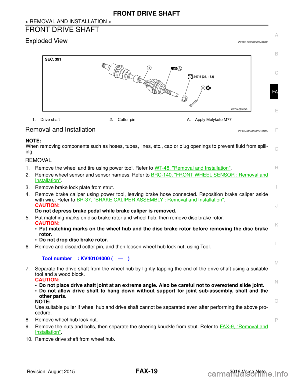
Exploded ViewINFOID:0000000012431898
Removal and InstallationINFOID:0000000012431899
NOTE:
When removing components such as hoses, tubes, lines, etc. , cap or plug openings to prevent fluid from spill-
ing.
REMOVAL
1. Remove the wheel and tire using power tool. Refer to WT-48, "Removal and Installation".
2. Remove wheel sensor and sensor harness. Refer to BRC-140, "
FRONT WHEEL SENSOR : Removal and
Installation".
3. Remove brake lock plate from strut.
4. Remove brake caliper using power tool, leaving brake hose connected. Reposition brake caliper aside with wire. Refer to BR-37, "
BRAKE CALIPER ASSEMBLY : Removal and Installation".
CAUTION:
Do not depress brake pedal while brake caliper is removed.
5. Put matching marks on disc brake rotor and wheel hub, then remove disc brake rotor. CAUTION:
• Put matching marks on the wheel hub and the disc brake rotor before removing the disc brake
rotor.
• Do not drop disc brake rotor.
6. Remove and discard cotter pin, and then loosen wheel hub lock nut, using Tool.
7. Separate the drive shaft from the wheel hub by lightly tapping the end of the drive shaft using a suitable tool and a wood block.
CAUTION:
• Do not place drive shaft joint at an extreme angle. Also be careful not to overextend slide joint.
• Do not allow drive shaft to ha ng down without support for joint sub-assembly, shaft and the
other parts.
NOTE:
Use suitable puller if wheel hub and drive shaft cannot be separated even after performing the above pro-
cedure.
8. Remove wheel hub lock nut.
9. Remove the nuts and bolts, then separate the steering knuckle from strut. Refer to FA X - 9 , "
Removal and
Installation".
10. Remove drive shaft from wheel hub.
1. Drive shaft 2. Cotter pinA. Apply Molykote M77
AWDIA0951GB
Tool number : KV40104000 ( — )
Revision: August 2015 2016 Versa Note
cardiagn.com
Page 1837 of 3641
FAX-20
< REMOVAL AND INSTALLATION >
FRONT DRIVE SHAFT
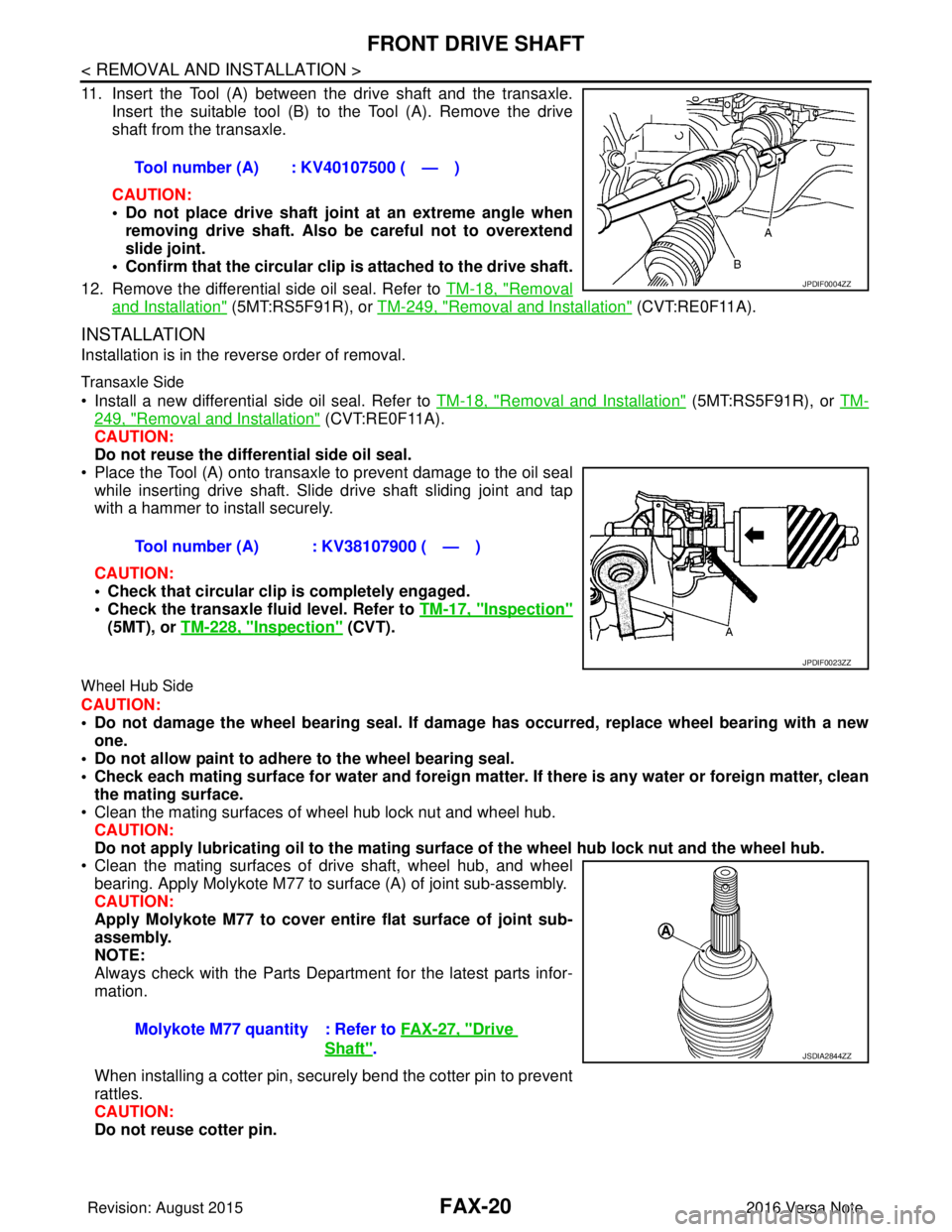
11. Insert the Tool (A) between the drive shaft and the transaxle.
Insert the suitable tool (B) to the Tool (A). Remove the drive
shaft from the transaxle.
CAUTION:
• Do not place drive shaft joint at an extreme angle when removing drive shaft. Also be careful not to overextend
slide joint.
• Confirm that the circular clip is attached to the drive shaft.
12. Remove the differential side oil seal. Refer to TM-18, "
Removal
and Installation" (5MT:RS5F91R), or TM-249, "Removal and Installation" (CVT:RE0F11A).
INSTALLATION
Installation is in the reverse order of removal.
Transaxle Side
• Install a new differential side oil seal. Refer to TM-18, "Removal and Installation" (5MT:RS5F91R), or TM-
249, "Removal and Installation" (CVT:RE0F11A).
CAUTION:
Do not reuse the differential side oil seal.
• Place the Tool (A) onto transaxle to prevent damage to the oil seal while inserting drive shaft. Slide drive shaft sliding joint and tap
with a hammer to install securely.
CAUTION:
• Check that circular clip is completely engaged.
• Check the transaxle fluid level. Refer to TM-17, "
Inspection"
(5MT), or TM-228, "Inspection" (CVT).
Wheel Hub Side
CAUTION:
• Do not damage the wheel bearing seal. If damage has occurred, replace wheel bearing with a new
one.
• Do not allow paint to adhere to the wheel bearing seal.
• Check each mating surface for water and foreign matter. If there is any water or foreign matter, clean
the mating surface.
• Clean the mating surfaces of wheel hub lock nut and wheel hub.
CAUTION:
Do not apply lubricatin g oil to the mating surface of the wh eel hub lock nut and the wheel hub.
• Clean the mating surfaces of drive shaft, wheel hub, and wheel
bearing. Apply Molykote M77 to surface (A) of joint sub-assembly.
CAUTION:
Apply Molykote M77 to cover entire flat surface of joint sub-
assembly.
NOTE:
Always check with the Parts Department for the latest parts infor-
mation.
When installing a cotter pin, securely bend the cotter pin to prevent
rattles.
CAUTION:
Do not reuse cotter pin. Tool number (A) : KV40107500 ( — )
JPDIF0004ZZ
Tool number (A) : KV38107900 ( — )
JPDIF0023ZZ
Molykote M77 quantity : Refer to
FAX-27, "Drive
Shaft".JSDIA2844ZZ
Revision: August 2015 2016 Versa Note
cardiagn.com
Page 1838 of 3641
FRONT DRIVE SHAFTFAX-21
< UNIT DISASSEMBLY AND ASSEMBLY >
CEF
G H
I
J
K L
M A
B
FA X
N
O P
UNIT DISASSEMBLY AND ASSEMBLY
FRONT DRIVE SHAFT
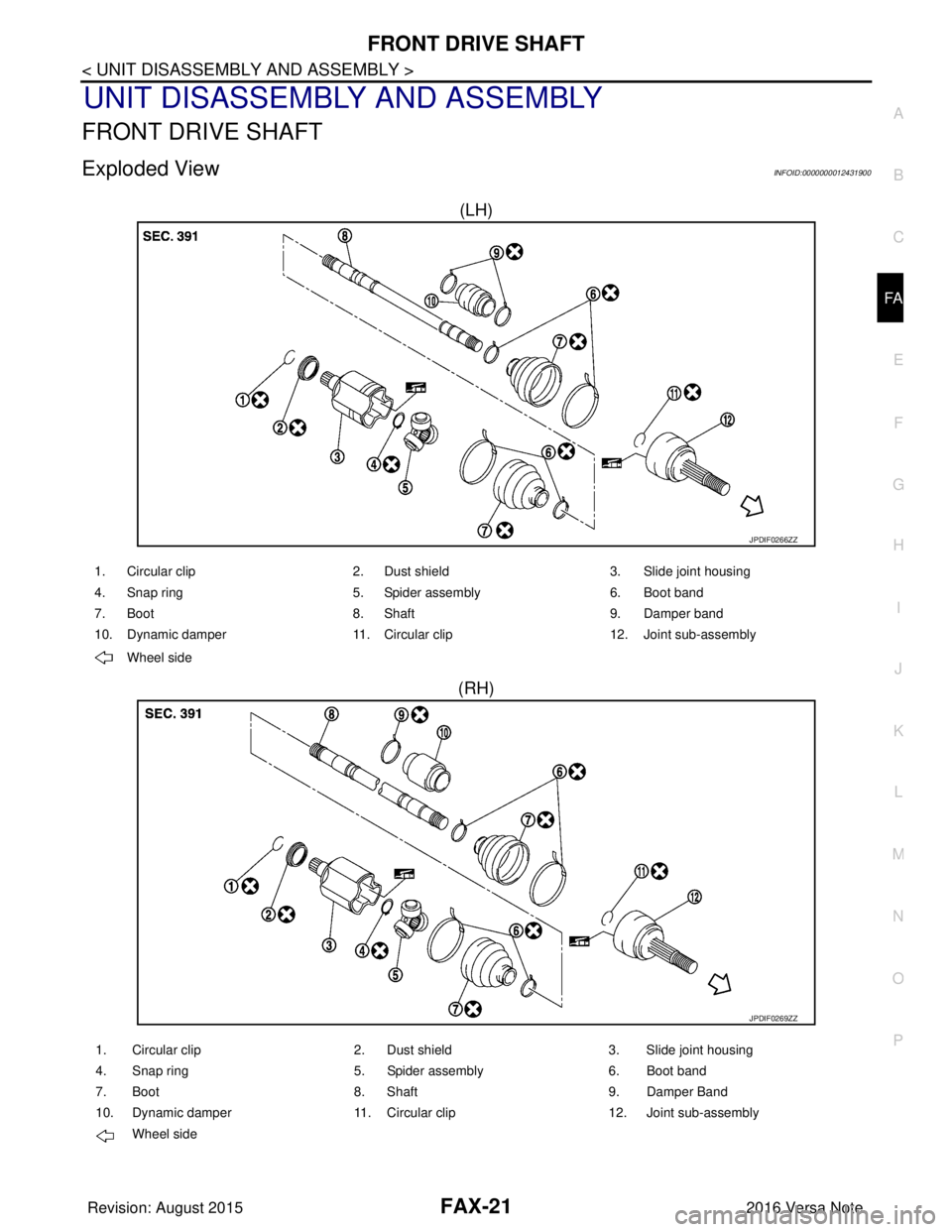
Exploded ViewINFOID:0000000012431900
(LH)
(RH)
JPDIF0266ZZ
1. Circular clip 2. Dust shield3. Slide joint housing
4. Snap ring 5. Spider assembly6. Boot band
7. Boot 8. Shaft9. Damper band
10. Dynamic damper 11. Circular clip12. Joint sub-assembly
Wheel side
JPDIF0269ZZ
1. Circular clip 2. Dust shield3. Slide joint housing
4. Snap ring 5. Spider assembly6. Boot band
7. Boot 8. Shaft9. Damper Band
10. Dynamic damper 11. Circular clip12. Joint sub-assembly
Wheel side
Revision: August 2015 2016 Versa Note
cardiagn.com
Page 1839 of 3641
FAX-22
< UNIT DISASSEMBLY AND ASSEMBLY >
FRONT DRIVE SHAFT
Disassembly and Assembly
INFOID:0000000012431901
DISASSEMBLY (WHEEL SIDE)
1. Mount the drive shaft in a vise. CAUTION:
When mounting the drive shaft in a vise, always use aluminum or copper plates between the vise
and the drive shaft.
2. Remove the boot bands and slide the boot back.
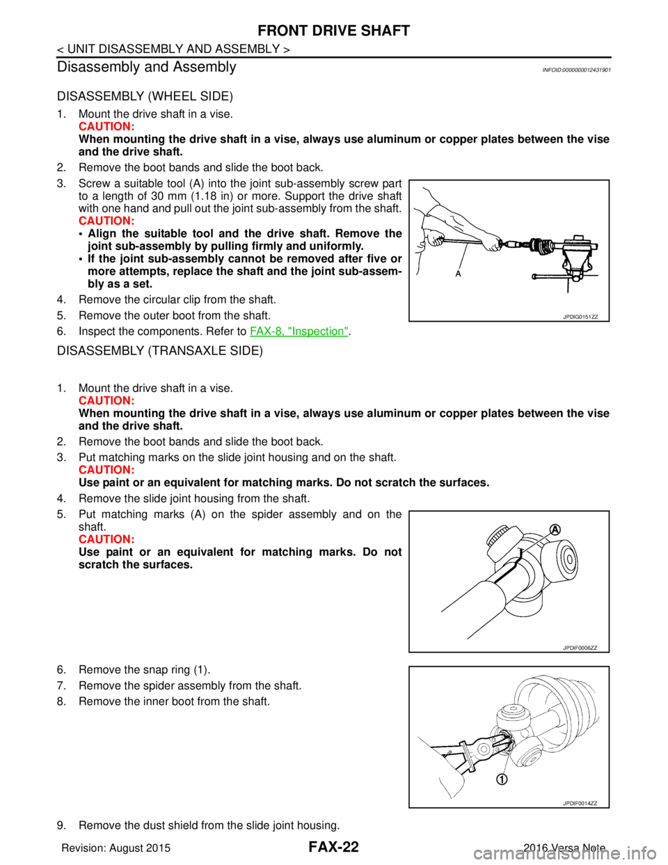
3. Screw a suitable tool (A) into the joint sub-assembly screw part to a length of 30 mm (1.18 in) or more. Support the drive shaft
with one hand and pull out the joint sub-assembly from the shaft.
CAUTION:
• Align the suitable tool and the drive shaft. Remove thejoint sub-assembly by pulli ng firmly and uniformly.
• If the joint sub-assembly cannot be removed after five or more attempts, replace the shaft and the joint sub-assem-
bly as a set.
4. Remove the circular clip from the shaft.
5. Remove the outer boot from the shaft.
6. Inspect the components. Refer to FAX-8, "
Inspection".
DISASSEMBLY (TRANSAXLE SIDE)
1. Mount the drive shaft in a vise. CAUTION:
When mounting the drive shaft in a vise, always use aluminum or copper plates between the vise
and the drive shaft.
2. Remove the boot bands and slide the boot back.
3. Put matching marks on the slide joint housing and on the shaft. CAUTION:
Use paint or an equivalent for matchi ng marks. Do not scratch the surfaces.
4. Remove the slide joint housing from the shaft.
5. Put matching marks (A) on the spider assembly and on the shaft.
CAUTION:
Use paint or an equivalent fo r matching marks. Do not
scratch the surfaces.
6. Remove the snap ring (1).
7. Remove the spider assembly from the shaft.
8. Remove the inner boot from the shaft.
9. Remove the dust shield from the slide joint housing.
JPDIG0151ZZ
JPDIF0006ZZ
JPDIF0014ZZ
Revision: August 2015 2016 Versa Note
cardiagn.com
Page 1840 of 3641
FRONT DRIVE SHAFTFAX-23
< UNIT DISASSEMBLY AND ASSEMBLY >
CEF
G H
I
J
K L
M A
B
FA X
N
O P
10. Remove the circular clip from the slide joint housing.
11. Clean the old grease from the slide joint housing with paper waste.
12. Remove the damper bands.
13. Remove the dynamic damper from the shaft.
14. Inspect the components. Refer to FA X - 8 , "
Inspection".
ASSEMBLY (WHEEL SIDE)
1. Clean the old grease from the joint sub-assembly using paper waste.
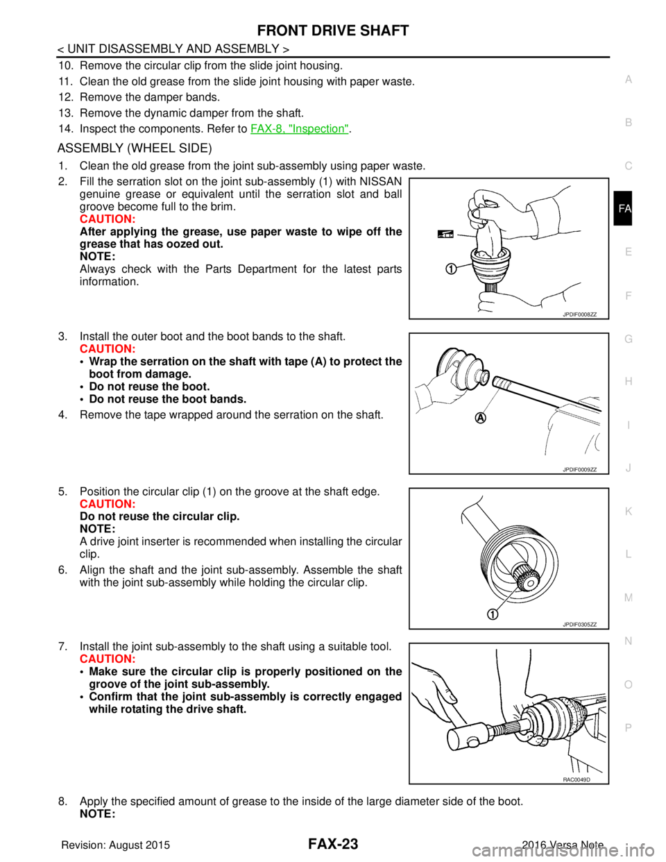
2. Fill the serration slot on the joint sub-assembly (1) with NISSAN
genuine grease or equivalent until the serration slot and ball
groove become full to the brim.
CAUTION:
After applying the grease, use paper waste to wipe off the
grease that has oozed out.
NOTE:
Always check with the Parts Department for the latest parts
information.
3. Install the outer boot and the boot bands to the shaft. CAUTION:
• Wrap the serration on the shaft with tape (A) to protect theboot from damage.
• Do not reuse the boot.
• Do not reuse the boot bands.
4. Remove the tape wrapped around the serration on the shaft.
5. Position the circular clip (1) on the groove at the shaft edge. CAUTION:
Do not reuse the circular clip.
NOTE:
A drive joint inserter is recommended when installing the circular
clip.
6. Align the shaft and the joint sub-assembly. Assemble the shaft with the joint sub-assembly while holding the circular clip.
7. Install the joint sub-assembly to the shaft using a suitable tool. CAUTION:
• Make sure the circular clip is properly positioned on the
groove of the joint sub-assembly.
• Confirm that the joint sub-assembly is correctly engaged
while rotating the drive shaft.
8. Apply the specified amount of grease to the inside of the large diameter side of the boot.
NOTE:
JPDIF0008ZZ
JPDIF0009ZZ
JPDIF0305ZZ
RAC0049D
Revision: August 2015 2016 Versa Note
cardiagn.com
Page 1844 of 3641
SERVICE DATA AND SPECIFICATIONS (SDS)FAX-27
< SERVICE DATA AND SPECIFICATIONS (SDS)
CEF
G H
I
J
K L
M A
B
FA X
N
O P
SERVICE DATA AND SPECIFICATIONS (SDS)
SERVICE DATA AND SPECIFICATIONS (SDS)
Wheel BearingINFOID:0000000012431902
Drive ShaftINFOID:0000000012431903
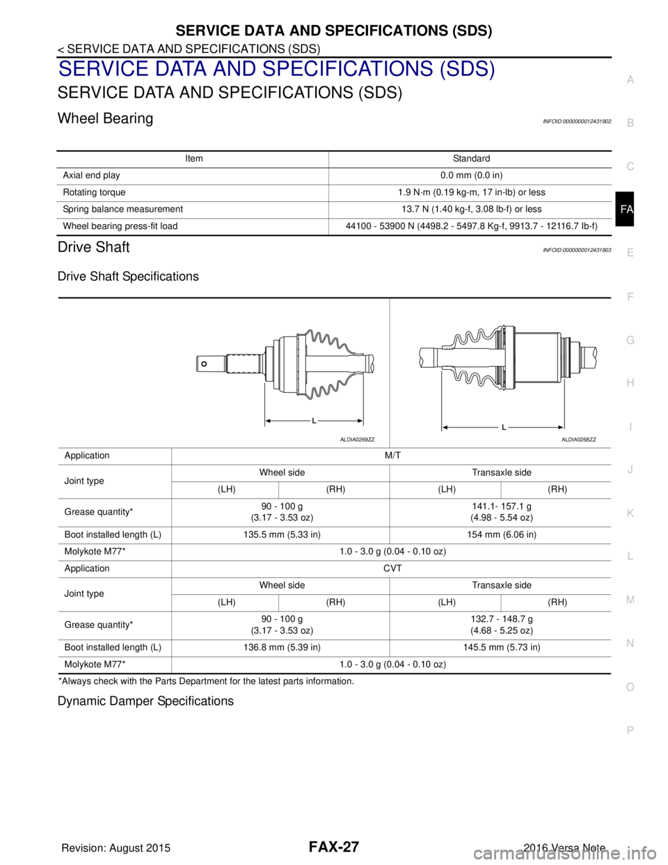
Drive Shaft Specifications
*Always check with the Parts Departme nt for the latest parts information.
Dynamic Damper Specifications
Item Standard
Axial end play 0.0 mm (0.0 in)
Rotating torque 1.9 N·m (0.19 kg-m, 17 in-lb) or less
Spring balance measurement 13.7 N (1.40 kg-f, 3.08 lb-f) or less
Wheel bearing press-fit load 44100 - 53900 N (4498.2 - 5497.8 Kg-f, 9913.7 - 12116.7 Ib-f)
Application M/T
Joint type Wheel side
Transaxle side
(LH) (RH) (LH)(RH)
Grease quantity* 90 - 100 g
(3.17 - 3.53 oz) 141.1- 157.1 g
(4.98 - 5.54 oz)
Boot installed length (L) 135.5 mm (5.33 in) 154 mm (6.06 in)
Molykote M77* 1.0 - 3.0 g (0.04 - 0.10 oz)
Application CVT
Joint type Wheel side
Transaxle side
(LH) (RH) (LH)(RH)
Grease quantity* 90 - 100 g
(3.17 - 3.53 oz) 132.7 - 148.7 g
(4.68 - 5.25 oz)
Boot installed length (L) 136.8 mm (5.39 in) 145.5 mm (5.73 in)
Molykote M77* 1.0 - 3.0 g (0.04 - 0.10 oz)
ALDIA0269ZZALDIA0268ZZ
Revision: August 2015 2016 Versa Note
cardiagn.com
Page 1846 of 3641
FSU-1
SUSPENSION
C
DF
G H
I
J
K L
M
SECTION FSU
A
B
FSU
N
O PCONTENTS
FRONT SUSPENSION
PRECAUTION ....... ........................................2
PRECAUTIONS .............................................. .....2
Precaution for Supplemental Restraint System
(SRS) "AIR BAG" and "SEAT BELT PRE-TEN-
SIONER" ............................................................. ......
2
Precaution for Procedure without Cowl Top Cover ......2
Precaution for Suspension ........................................2
PREPARATION ............................................3
PREPARATION .............................................. .....3
Special Service Tools .......................................... ......3
Commercial Service Tools ........................................3
SYMPTOM DIAGNOSIS ...............................5
NOISE, VIBRATION AND HARSHNESS
(NVH) TROUBLESHOOTING ........................ .....
5
NVH Troubleshooting Chart ................................ ......5
PERIODIC MAINTENANCE ..........................6
FRONT SUSPENSION ASSEMBLY .............. .....6
Inspection ............................................................ ......6
WHEEL ALIGNMENT ..........................................7
Inspection ............................................................ ......7
Adjustment ................................................................8
REMOVAL AND INSTALLATION ................9
FRONT COIL SPRING AND STRUT ............. .....9
Exploded View .................................................... ......9
Removal and Installation ...........................................9
TRANSVERSE LINK .........................................10
Exploded View ..................................................... ....10
Removal and Installation .........................................10
Inspection ................................................................10
FRONT STABILIZER ........................................12
Exploded View .........................................................12
Removal and Installation .........................................12
Inspection ................................................................13
UNIT REMOVAL AND INSTALLATION ......14
FRONT SUSPENSION MEMBER .....................14
Exploded View ..................................................... ....14
Removal and Installation .........................................14
Inspection ................................................................15
UNIT DISASSEMBLY AND ASSEMBLY ....16
FRONT COIL SPRING AND STRUT ................16
Exploded View ..................................................... ....16
Disassembly and Assembly .....................................16
Inspection ................................................................19
Disposal ...................................................................19
SERVICE DATA AND SPECIFICATIONS
(SDS) ............... .......................................... ...
20
SERVICE DATA AND SPECIFICATIONS
(SDS) .................................................................
20
Wheel Alignment (Unladen*1) ..................................20
Ball Joint .............................................................. ....20
Wheelarch Height (Unladen*) ..................................21
Revision: August 2015 2016 Versa Note
cardiagn.com