Page 273 of 290

Slide the new wheel onto the wheel hub and
push it on.
Wheels with centering by wheel bolts:
XVehicles with alloy wheels: take the short
wheel bolts that secure the steel spare wheel
out of the vehicle tool kit.
XScrew in the wheel bolts and tighten them
lightly.
For wheels with wheel nuts:
XFront wheels with wheel nut covers: press the
wheel nut covers onto the wheel nuts.
XScrew in the three wheel nuts over the fixing
discs of the wheel nut cover.
XTurn the wheel so that the wheel bolts are in
the middle of the holes.
XScrew on the rest of the wheel nuts.
XSlightly tighten all the wheel nuts.
Lowering the vehicle
GWARNING
The wheels could work loose if the wheel nuts and bolts are not tightened to the specified
tightening torque. There is a risk of accident.
Have the tightening torque immediately
checked at a qualified specialist workshop
after a wheel is changed.
!Only use the jack pump lever middle rod and
the rod with the largest diameter as a lug
wrench extension. Only slide the middle rod
as far as it will go onto the lug wrench. The
rods may otherwise bend and be distorted to
such an extent that they can no longer be
used as a pump lever for the jack.
!Vehicles with Super Single tires: if you
install the spare wheel, do not exceed the
maximum speed of 40 mph (60 km/h) and do
not drive further than 65 miles(100 km).
The transmission could otherwise be dam-
aged by the difference in wheel rotation
speeds.
Tightening torque pattern
:—B
Wheel bolts or wheel nuts
XUsing the pump lever, slowly turn the lowering
screw on the jack through approximately one revolution and carefully lower the vehicle
(
Ypage 268).
XPut the jack aside.
XPull the rod with the smallest diameter off the
pump lever.
The shortened pump lever serves as a lug
wrench extension.
XStarting with the middle rod, slide the lug
wrench extension as far as it will go onto the
lug wrench.
XUsing the extended lug wrench, tighten the
wheel bolts evenly in a crosswise pattern in
the sequence indicated ( :toB).
Tighten the wheel bolts to the following tight-
ening torques:
RSteel wheel 177 lb-ft(240 Nm)
RAlloy wheel 133 lb-ft(180 Nm)
Tighten the wheel nuts to a tightening torque
of 133 lb-ft (180 Nm).
XPush the piston on the hydraulic jack in again
and close the pressure release screw.
XVehicles with all-wheel drive: turn the jack
spindle clockwise as far as it will go
(
Ypage 268).
XStow the jack and the rest of the vehicle tools
in the vehicle again.
iYou can now install the hub caps on steel
wheels with wheel bolts. The installing proce-
dure depends on whether the hub cap acts as
a trim that covers the whole wheel, or just
covers the center.
XWheel with hub cap: position the opening for
the tire valve in the hub cap over the tire valve.
XPush the edge of the hub cap with both hands against the wheel until it clicks into place.
Changing wheels271
Wheels and tires
Z
Page 274 of 290

Make sure the hub cap retaining catches
engage on the steel wheel.
XWheel with central hub cap: position the
retaining lugs of the central hub cap over the
wheel bolts.
XHit the middle of the hub cap to engage it on
the wheel.
XSecure the faulty wheel in the spare wheel
bracket (Ypage 273).
XVehicles with Super Single tires: transport the
defective rear wheel in the load area. The rear
wheel is too large for the spare wheel bracket.
XCheck the tire pressure of the newly mounted
wheel and adjust it if necessary.
Observe the recommended tire pressure
(
Ypage 250).
XRetighten the wheel bolts or wheel nuts to the
specified tightening torque after the vehicle
has been driven for 30 miles (50 km).
When using a wheel or spare wheel with a new or
newly painted wheel rim, have the wheel bolts or
nuts retightened again after approximately 600
to 3,000 miles (1,000 to 5,000 km). Observe the
specified tightening torque.
iVehicles with the tire pressure monitor sys-
tem: all mounted wheels must be equipped
with functioning sensors.
Wheel and tire combination
General notes
!
Retreaded tires are neither tested nor rec-
ommended for Sprinter vehicles, since previ-
ous damage cannot always be detected on
retreaded tires. We can therefore not guar-
antee driving safety. Do not mount used tires if you have no information about their previ-
ous usage.
The recommended tire pressures can be found:
Ron the Tire and Loading Information placard9
on the B-pillar on the driver's side
Ron the tire pressure table on the B-pillar on the driver's side
The recommended tire pressure can also be
found in the "Tire pressure table" section in this
Operator's Manual (
Ypage 257). The wheel/tire
combination for your vehicle can be found on the tire pressure table. Further information on
wheel/tire combination can be obtained at any
qualified specialist workshop.
Check tire pressures regularly and only when
the tires are cold. Observe the notes on the rec-
ommended tire pressure (
Ypage 250).
Follow the maintenance recommendations in
the tire manufacturer's warranty book in your
vehicle documents.
Notes on the vehicle equipment – always equip
the vehicle:
Rwith tires of the same size across an axle (left
and right)
Rwith the same type of tires on all wheels at a
given time (summer tires, winter tires)
Tires that have been specially designed and
approved for your vehicle are marked with MO
(Mercedes-Benz Original). You can find this
identification on the tires themselves and in the
following table.
iNot all wheel/tire combinations can be
installed at the factory in all countries.
Spare wheel
Important safety notes
GWARNING
Wheel and tire dimensions as well as the type of tire can vary between the spare wheel and
the wheel to be replaced. When the spare
wheel is mounted, driving characteristics may be severely affected. There is a risk of an acci-
dent.
In order to reduce risks:
Ryou should therefore adapt your driving
style and drive carefully.
Rnever mount more than one spare wheel
that differs from the wheel to be replaced.
Ronly use a spare wheel that differs from the
wheel to be replaced for a short time.
Rdo not deactivate ESP®.
Rhave a spare wheel that differs from the
wheel that has been changed replaced at
the nearest qualified specialist workshop.
9Only for vehicles with a gross weight of less than 10,000 lbs (4,536 kg).
272Spare wheel
Wheels and tires
Page 275 of 290

You must observe the correct wheel and
tire dimensions as well as the wheel type.
When using a spare wheel of a different size, do
not exceed the maximum speed of 80 km/h.
General notes
!
Check the spare wheel regularly to see that
it is secure and has the prescribed tire pres-
sure.
The procedure for mounting the spare wheel is
described in "Mounting a wheel" (
Ypage 267).
The following should be checked regularly, par-
ticularly prior to long journeys:
Rthe tire pressure of the spare wheel, which
should then be corrected if necessary
(
Ypage 250).
Rthe fastenings of the spare wheel bracket.
The spare wheel is located in a spare wheel
bracket under the rear of the vehicle.
Replace the tires after 6 years at the latest,
regardless of wear. This also applies to the spare
wheel.
iIf you have mounted a spare wheel, the tire
pressure monitor (Ypage 253) will not func-
tion for this wheel. The spare wheel is not
equipped with a sensor for monitoring tire
pressure.
Removing and installing the spare
wheel
Cargo Van/Passenger Van
Bolt covers for the safety catches (example: Cargo
Van)
Removing
XOpen the rear doors.
XPlace a screwdriver into recesses ;and then
pry off covers :.
XUsing the lug wrench from the vehicle tool kit
(Ypage 240), unscrew the now visible bolts
counter-clockwise by approximately 20 turns.
Spare wheel carrier under the vehicle
XSlightly raise spare wheel bracket Aand
unhook left-hand retaining hook =.
XAssemble the pump lever for the jack and
slide it into sleeve?on spare wheel bracket
A.
XRaise spare wheel bracket Awith the pump
lever and unhook right-hand retaining hook
=.
XSlowly lower spare wheel bracket Adown to
the ground.
XLift spare wheel bracket Aslightly and pull
the pump lever out of sleeve ?.
Spare wheel in the spare wheel carrier
Spare wheel273
Wheels and tires
Z
Page 276 of 290

XUse the pump lever to lift the spare wheel
beyond the rear edge of the spare wheel car-
rier.
XCarefully remove the spare wheel from sparewheel bracket A.
The spare wheel is heavy. When the spare
wheel is removed, the center of gravity
changes due to the heavy weight of the wheel.
The spare wheel may slip down or tip over.
Installing
XCarefully place the spare wheel onto spare
wheel bracket A.
The spare wheel is heavy. When you place the
spare wheel onto spare wheel bracket A, the
center of gravity changes due to the weight of
the wheel. The spare wheel may slip down or
tip over.
XSlide the pump lever for the jack into
sleeve ?on spare wheel bracket A.
XRaise spare wheel bracket Awith the pump
lever and attach right-hand retaining hook =.
XSlightly raise spare wheel bracketAand
attach left-hand retaining hook =.
XPull the pump lever out of sleeve ?.
XUsing the lug wrench, tighten the retaining
hook bolts by turning them clockwise.
XReplace and engage covers:.
XClose the rear doors.
Cab Chassis version
Removing
XLoosen fender nuts=manually and then
remove them.
XLoosen nuts ;as far as the thread end.
XSlightly raise spare wheel bracket ?and
unhook left-hand retaining hook :.
XAssemble the pump lever for the jack and
slide it into the sleeve on the right-hand side
of spare wheel bracket?.
XRaise spare wheel bracket ?with the pump
lever and unhook right-hand retaining
hook :.
XSlowly lower spare wheel bracket ?down to
the ground.
XLift spare wheel bracket ?slightly and pull
the pump lever out of the sleeve.
XUse the pump lever to lift the spare wheel
beyond the rear edge of spare wheel
bracket ?.
XCarefully remove the spare wheel from the
bracket.
The spare wheel is heavy. When the spare
wheel is removed, the center of gravity
changes due to the heavy weight of the wheel.
The spare wheel may slip down or tip over.
Installing
XCarefully place the spare wheel onto spare
wheel bracket ?.
The spare wheel is heavy. When you place the
spare wheel onto spare wheel bracket ?, the
center of gravity changes due to the weight of
the wheel. The spare wheel may slip down or
tip over.
XRaise spare wheel bracket ?with the pump
lever and attach right-hand retaining hook :.
XSlightly raise spare wheel bracket?and
attach left-hand retaining hook :.
XPull the pump lever out.
XTighten nuts;.
XPut fender nuts =in place and tighten them.
274Spare wheel
Wheels and tires
Page 277 of 290

Useful information
This Operator's Manual describes all models as
well as standard and optional equipment of your
vehicle that were available at the time of going
to print. Country-specific variations are possi-
ble. Note that your vehicle may not be equipped
with all of the described functions. This also
applies to systems and functions relevant to
safety.
Read the information on qualified specialist
workshops (
Ypage 26).
Vehicle electronics
Tampering with the engine electron-
ics
GWARNING
Always have work on the engine electronics
and related components carried out at a quali-
fied specialist workshop. Otherwise, the vehi-
cle's operating safety could be affected.
!Only have engine electronics and the corre-
sponding parts, such as control units, sensors or connector leads, serviced in a qualified
specialist workshop. Otherwise, the vehicle
parts may wear more quickly. This can lead to
loss of the New Vehicle Limited Warranty.
Installing electrical or electronic
equipment
GWARNING
If you operate mobile communication equip-
ment while driving, you will be distracted from traffic conditions. You could also lose control
of the vehicle. There is a risk of an accident.
Only operate this equipment when the vehicle
is stationary.
You and others can suffer health-related dam-
age through electromagnetic radiation. By using an exterior antenna, a possible health risk
caused by electromagnetic fields, as discussed
in scientific circles, is taken into account. Only
have the exterior antenna installed by a qualified
specialist workshop. Electrical and electronic devices may have a
detrimental effect on both the comfort and the
operating safety of the vehicle. If equipment of
this kind is installed, its electromagnetic com-
patibility must be checked and verified.
If these devices are linked to functions associ-
ated with resistance to interference, they must
have type approval. This applies to the device or
its interfaces to the vehicle electronics, e.g.
charging brackets.
A telephone or two-way radio to be installed in
the vehicle must be approved. Further informa-
tion can be obtained from any Sprinter Dealer.
For operation of mobile phones and two-way
radios, Mercedes-Benz recommends connec-
tion to an approved exterior antenna. This is the
only way to ensure optimum reception quality
inside the vehicle and to minimize mutual inter-
ference between the vehicle electronics, mobile
phones and two-way radios.
The transmission output of the mobile phone or
two-way radio may not exceed the following
maximum transmission output (PEAK):
Frequency rangeMaximum trans-
mission output
(PEAK)
Shortwave
(f < 50 MHz)100 W
4 m waveband30 W
2 m waveband50 W
Trunked radio/Tetra35 W
70 cm waveband35 W
GSM/UMTS/LTE10 W
Vehicle electronics275
Technical data
Z
Page 278 of 290
Identification plates
Vehicle identification plate with vehi-
cle identification number (VIN)
Vehicleidentification plat efor vehicles or chassi s
on th ebase of th edriver' sseat
XOpen th edriver’s door .
You will see vehicl eidentification plat e:
wit hth evehicl eidentification number (VIN),
th epain tcode and th epermissible weigh t
data.
Example: vehicl eidentification plat e(US vehicles)
Example: chassi sidentification plat e(US vehicles)
Example: chassi sidentification plat e(vehicles for
Canada)
;
VIN
=Pain tcode
Engin ecompartmen t
?
VIN (stampe don th erear wall of th eengin e
compartment)
AEngin enumber (stampe don th ecrankcase)
BEmission Control Information and engin e
oil10instruction labels
XOpen th ehoo d (Ypage 218).
Example: Emission Control Information label
10Alsoobserv eth enote son engin eoil for diesel engines in th e"Technical data" section.
276Identification plates
Technical data
Page 279 of 290

iSuch data is vehicle-specific and may differ
from that shown. Always observe the specifi-
cations on your vehicle's identification plate.
Engine number
The engine number is stamped on the crank-
case. More information may be obtained at any
qualified specialist workshop.
Service products and capacities
Important safety notes
GWARNING
Service products may be poisonous and haz-
ardous to health. There is a risk of injury.
Comply with instructions on the use, storage
and disposal of service products on the labels
of the respective original containers. Always
store service products sealed in their original
containers. Always keep service products out
of the reach of children.
HEnvironmental note
Dispose of service products in an environ-
mentally responsible manner.
Service products include the following:
RFuels, e.g. diesel
RAdditives for the exhaust gas aftertreatment,
e.g. Diesel Exhaust Fluid (DEF)
RLubricants, e.g. engine oil, transmission oil
RCoolant
RBrake fluid
RWasher fluid
RClimate control system refrigerants
Approved service products comply with the
highest quality standards and are listed in the
MB Specifications for Service Products. Only
use service products approved for the vehicle.
This is an important condition for the warranty.
You will recognize the approved service prod-
ucts by the inscription on the container: MB
Approval (e.g. MB Approval 228.5)
Other identifications and recommendations
refer to quality level or a specification according to an MB Sheet Number (e.g. MB 228.5). They
are therefore not necessarily approved.
Further information can be obtained at any
qualified specialist workshop.
Additives for approved service products are nei-
ther required nor permitted. Approved fuel addi- tives are the exception. Additives can cause
engine damage and must therefore not be
added to the service products.
The use of additives is always the responsibility
of the vehicle operator. The use of additives may
result in the restriction or loss of yo ur Li
mited
Warranty entitlements.
Fuel
Important safety notes
GWARNING
Fuel is highly flammable. Improper handling of
fuel creates a risk of fire and explosion.
Avoid fire, open flames, smoking and creating
sparks under all circumstances. Switch off the
engine and, if applicable, the auxiliary heating
before refueling.
GWARNING
Fuel is poisonous and hazardous to health.
There is a risk of injury.
You must make sure that fuel does not come into contact with your skin, eyes or clothing
and that it is not swallowed. Do not inhale fuel
vapors. Keep fuel away from children.
If you or others come into contact with fuel,
observe the following:
RWash away fuel from skin immediately
using soap and water.
RIf fuel comes into contact with your eyes,
immediately rinse them thoroughly with
clean water. Seek medical assistance with-
out delay.
RIf fuel is swallowed, seek medical assis-
tance without delay. Do not induce vomit-
ing.
RImmediately change out of clothing which
has come into contact with fuel.
Service products and capacities277
Technical data
Z
Page 280 of 290

When handling, storing and disposing of fuels,
please observe the relevant regulations.
Tank contents
Depending on equipment, the total capacity of
the fuel tank may vary.
Vehicle typeTotal capa-cityof which
reserve fuel
2500
3500Approx-imately
26.4 US gal (100 l)Approx-
imately
5.0 US gal
(19 l)
All-wheel-
drive vehicleApprox-
imately
24.6 US gal (93 l)
Diesel
Fuel grade
GWARNING
If you mix diesel fuel with gasoline, the flash
point is lower than that of pure diesel fuel.
When the engine is running, exhaust system
components could overheat without being
noticed. There is a risk of fire.
Never refuel with gasoline. Never mix gasoline with diesel fuel.
!Filter the fuel before transferring it to the
vehicle if you are refueling the vehicle from
barrels or containers.
This will prevent malfunctions in the fuel sys-
tem due to contaminated fuel.
!You will damage the diesel engine if you do
not refuel with ULSD or a diesel fuel with a
sulfur content of more than 15 ppm.
!Do not use the following:
RMarine diesel
RHeating oil
RBio-diesel
RVegetable oil
RGasoline
RParaffin
RKerosene Do not mix such fuels with diesel fuel and do
not use any special additives. This can other-
wise lead to engine damage. This does not
include flow improver additives. For further
information, see "Flow improvers".
You will generally find information about the fuel
grade on the filling pump. If there is no identifi-
cation on the filling pump, consult a gas station
attendant.
For more information ab out re
fueling
(Ypage 127).
Diesel at very low outside temperatures
GWARNING
If you heat fuel system components, e.g. with
a hot-air gun or open flame, these compo-
nents could be damaged. This can cause fuel
to escape and ignite. Depending on the type
of damage, fuel may also not escape until the
engine is running. There is a risk of fire and
explosion.
Never heat fuel system components. Contact
a qualified specialist workshop to rectify the
malfunction.
Refill only with commercially available ULTRA-
LOW SULFUR DIESEL (ULSD, maximum sulfur
content 15 ppm), which fulfills the ASTM D975
standard.
The flow properties of diesel may be inadequate
at low outside temperatures due to paraffin sep-
aration.
iMalfunctions resulting from paraffin sepa-
ration can only be rectified by heating the
entire fuel system. Park the vehicle in a
heated garage, for example.
To prevent operating problems, diesel with bet-
ter flow qualities is available during the winter
months. You can obtain information at the gas
station or from your fuel supplier.
Your vehicle is equipped with a fuel preheating
system. This improves the flow properties of the
diesel by approximately 46 ‡ (8 †). ULTRA-
LOW SULFUR DIESEL can be used without ris k
o
f malfunction down to an outside temperature
of approximately 14 ‡ ( Ò10 †).
278Service products and capacities
Technical data
 1
1 2
2 3
3 4
4 5
5 6
6 7
7 8
8 9
9 10
10 11
11 12
12 13
13 14
14 15
15 16
16 17
17 18
18 19
19 20
20 21
21 22
22 23
23 24
24 25
25 26
26 27
27 28
28 29
29 30
30 31
31 32
32 33
33 34
34 35
35 36
36 37
37 38
38 39
39 40
40 41
41 42
42 43
43 44
44 45
45 46
46 47
47 48
48 49
49 50
50 51
51 52
52 53
53 54
54 55
55 56
56 57
57 58
58 59
59 60
60 61
61 62
62 63
63 64
64 65
65 66
66 67
67 68
68 69
69 70
70 71
71 72
72 73
73 74
74 75
75 76
76 77
77 78
78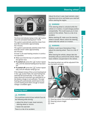 79
79 80
80 81
81 82
82 83
83 84
84 85
85 86
86 87
87 88
88 89
89 90
90 91
91 92
92 93
93 94
94 95
95 96
96 97
97 98
98 99
99 100
100 101
101 102
102 103
103 104
104 105
105 106
106 107
107 108
108 109
109 110
110 111
111 112
112 113
113 114
114 115
115 116
116 117
117 118
118 119
119 120
120 121
121 122
122 123
123 124
124 125
125 126
126 127
127 128
128 129
129 130
130 131
131 132
132 133
133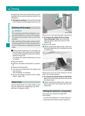 134
134 135
135 136
136 137
137 138
138 139
139 140
140 141
141 142
142 143
143 144
144 145
145 146
146 147
147 148
148 149
149 150
150 151
151 152
152 153
153 154
154 155
155 156
156 157
157 158
158 159
159 160
160 161
161 162
162 163
163 164
164 165
165 166
166 167
167 168
168 169
169 170
170 171
171 172
172 173
173 174
174 175
175 176
176 177
177 178
178 179
179 180
180 181
181 182
182 183
183 184
184 185
185 186
186 187
187 188
188 189
189 190
190 191
191 192
192 193
193 194
194 195
195 196
196 197
197 198
198 199
199 200
200 201
201 202
202 203
203 204
204 205
205 206
206 207
207 208
208 209
209 210
210 211
211 212
212 213
213 214
214 215
215 216
216 217
217 218
218 219
219 220
220 221
221 222
222 223
223 224
224 225
225 226
226 227
227 228
228 229
229 230
230 231
231 232
232 233
233 234
234 235
235 236
236 237
237 238
238 239
239 240
240 241
241 242
242 243
243 244
244 245
245 246
246 247
247 248
248 249
249 250
250 251
251 252
252 253
253 254
254 255
255 256
256 257
257 258
258 259
259 260
260 261
261 262
262 263
263 264
264 265
265 266
266 267
267 268
268 269
269 270
270 271
271 272
272 273
273 274
274 275
275 276
276 277
277 278
278 279
279 280
280 281
281 282
282 283
283 284
284 285
285 286
286 287
287 288
288 289
289
Vehicleidentification plat efor vehicles or chassi s
on th ebase of th edriver' sseat
XOpen th edriver")