Page 161 of 290

Uncoupling a trailer
GWARNING
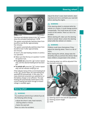
If you uncouple a trailer with the overrun
brake engaged, you could trap your hand
between the vehicle and the trailer drawbar.
There is a risk of injury.
Do not uncouple a trailer if the overrun brake
is engaged.
!Do not disconnect a trailer with an engaged
overrun brake. Otherwise, your vehicle could
be damaged by the rebounding of the overrun
brake.
XMake sure the selector lever of the automatic
transmission is in position P.
XApply the parking brake of the vehicle.
XClose all doors.
XApply the parking brake of the trailer.
XIn addition, secure the trailer against rolling
away with a wheel chock or similar object.
XRemove the trailer cable and safety chains
and decouple the trailer.
Permissible trailer loads and trailer
drawbar noseweights
Weight information
!On vehicles with a permissible gross vehicle
weight of 11030 lbs (5003 kg), the permissi-
ble gross combination weight is less than the total of the permissible gross vehicle weight
and the permissible trailer load. Exceeding
the permissible gross combination weight can
lead to damage to the drivetrain, to the trans-
mission or to the trailer tow hitch.
If the vehicle or the trailer is fully laden, the
relevant value for the permissible gross vehi-
cle weight or the permissible trailer load is
therefore lower. In this case, the trailer or the
vehicle may only be partially loaded.
The gross trailer weight (GTW) is calculated by
adding the weight of the trailer to the weight of
the load and equipment.
The maximum gross vehicle weight is vehicle-
specific and equipment-dependent: 5,000 lbs
(2,268 kg) or 7,500 lbs (3,402 kg).
The maximum permissible trailer drawbar nose- weight on the ball coupling is 500 lbs (227 kg) or 750 lbs (340 kg). The actual noseweight may not
exceed the value given on the identification
plates of the trailer tow hitch or the trailer. If the
values vary, the lowest value always applies.
The gross combination weight rating (GCWR) is
calculated by adding the gross weight of the
trailer to the gross vehicle weight including a
driver's weight of approximately 150 lbs (68 kg).
The permissible Gross Combination Weight Rat-
ing is vehicle-specific and depends on the equip-
ment level.
When driving with a trailer, you should not
exceed the permitted Gross Combination
Weight Rating (GCWR).
The permissible values, which must not be
exceeded, can be found in your vehicle docu-
ments and on the trailer tow hitch type plates for
the trailer and the vehicle (
Ypage 276). The
basic values approved by the manufacturer can
also be found in the "Technical data" section
(
Ypage 286). If the values vary, the lowest
value always applies.
Loading a trailer
!Utilize the maximum permissible nose-
weight as fully as possible. Do not allow the
weight to fall below the minimum permissible
noseweight, otherwise the trailer may come
loose.
RYou must distribute the load on the vehicle
and trailer so that the permitted maximum
values for the gross vehicle weight (GVWR),
gross trailer weight (GTW) and gross com-
bined weight (GCWR) as well as permitted
gross axle loads (GAWR) and noseweight
(TWR) of your vehicle are not exceeded.
RAdd the drawbar noseweight on the ball cou-
pling (TWR) to the rear axle load. This will pre-
vent you from exceeding the permissible
gross axle weight (GAWR).
RAdd the drawbar noseweight on the ball cou-
pling (TWR) to the vehicle payload. This will
prevent you from exceeding the permissible
gross vehicle weight (GVWR).
Checking the vehicle and trailer weight
RMake sure the weights of the towing vehicle
and the trailer comply with the maximum per-
missible values. Have the vehicle/trailer com-
bination weighed on a calibrated weigh-
bridge. The vehicle/trailer combination con-
sists of the towing vehicle including the driver,
Towing a trailer159
Driving and parking
Z
Page 162 of 290

passengers and load, as well as the loaded
trailer.
RCheck the maximum permissible gross axle
weight rating of the front and rear axles
(GAWR), the gross trailer weight (GTW), the
gross combination weight rating (GCWR) and
the noseweight of the trailer drawbar (TWR).
Trailer power supply
!
Incorrect wiring of the connector plug could,
under certain circumstances, cause malfunc-
tions in the vehicle's other electronic sys-
tems. We therefore recommend having the
connector plug wired at a qualified specialist
workshop.
!You can connect accessories with a maxi-
mum power consumption of 240 W to the
permanent power supply.
You must not charge a trailer battery using the
power supply.
Your vehicle may be equipped with various elec-
trical installations for trailer towing. Depending
on your trailer, you may need an adapter to con-
nect the electrical system of the trailer with that
of the vehicle.
The trailer socket of your vehicle is equipped at the factory with a permanent power supply.
The permanent power supply is on the trailer
socket pin assignment 4.
Note that the permanent power supply of the
trailer is not switched off when the on-board
voltage is low. This can completely discharge
the starter battery of your vehicle.
Further information on the electrical equipment
currently installed on your vehicle and on instal-
ling trailer electrics can be obtained at any quali-
fied specialist workshop.
160Towing a trailer
Driving and parking
Page 163 of 290

Useful information
This Operator's Manual describes all models as
well as standard and optional equipment of your
vehicle that were available at the time of going
to print. Country-specific variations are possi-
ble. Note that your vehicle may not be equipped
with all of the described functions. This also
applies to systems and functions relevant to
safety.
Read the information on qualified specialist
workshops (
Ypage 26).
Important safety notes
GWARNING
If you are driving and reach through the steer- ing wheel to operate the adjustment knob,
you could lose control of the vehicle. There is
a risk of an accident and injury.
Only operate the adjustment knobs when thevehicle is stationary. Do not reach through the
steering wheel when driving.
GWARNING
If you operate information systems and com-
munication equipment integrated in the vehi-
cle while driving, you will be distracted from
traffic conditions. You could also lose control
of the vehicle. There is a risk of an accident.
Only operate the equipment when the traffic
situation permits. If you are not sure that this
is possible, park the vehicle paying attention
to traffic conditions and operate the equip-
ment when the vehicle is stationary.
GWARNING
If the instrument cluster has failed or mal-
functioned, you may not recognize function
restrictions in systems relevant to safety. The
operating safety of your vehicle may be
impaired. There is a risk of an accident.
Drive on carefully. Have the vehicle checked
at a qualified specialist workshop immedi-
ately. You must observe the legal requirements for the
country in which you are currently driving when
operating the on-board computer.
The on-board computer display only shows mes-
sages and warnings from certain systems. You
should therefore make sure your vehicle is oper-
ating safely at all times. If the operating safety of
your vehicle is impaired, stop the vehicle as
soon as possible, paying attention to road and
traffic conditions. Then consult a qualified spe-
cialist workshop.
Instrument cluster
Overview
:Instrument cluster on vehicles without
steering wheel buttons
;Instrument cluster in vehicles with steering-
wheel buttons
=Adjustment buttons fand g
?Reset button 9
AService button Ë(engine oil level check)
BMenu button 4
You will find a full overview of the instrument
cluster in the "At a glance" section (
Ypage 32).
The display in the instrument cluster is activated when you:
Ropen the driver's door
Rturn the key to position 2in the ignition lock
Rpress the 9reset button
Rswitch on the lights
Instrument cluster161
On-board computer and displays
Z
Page 164 of 290

The display switches off automatically after
approximately 30 seconds if:
Rthe key is in position0in the ignition lock.
Rthe vehicle lighting is not switched on.
Instrument lighting
When the lights are switched on, you can adjust
the brightness of the instrument cluster lighting
using the fand gbuttons.
XTo brighten: press thefbutton.
XTo dim: press the gbutton.
iVehicles with automatic headlamp mode:
the instrument lighting also adapts to auto-
matic headlamp mode.
Tachometer
!
Do not drive in the overrevving range, as this
could damage the engine.
HEnvironmental note
Avoid driving at high engine speeds. This
unnecessarily increases the fuel consumption
of your vehicle and harms the environment as
a result of increased emissions.
The red band in the tachometer indicates the
engine's overrevving range.
To protect the engine, the fuel supply is inter-
rupted when the red band is reached.
Outside temperature
You should pay special attention to road condi-
tions when temperatures are around the freez-
ing point.
On vehicles without steering wheel buttons
(
Ypage 163) and on vehicles with steering
wheel buttons (Ypage 167), the outside tem-
perature display is in the display.
Changes in the outside temperature are dis-
played after a short delay.
Speedometer
The speed can also be shown in the display. You
can find information on the digital speedometer for vehicles without steering wheel buttons
under (
Ypage 163) and for vehicles with steer-
ing wheel buttons under (Ypage 167).
iIn some countries, a warning sounds when
the vehicle reaches the maximum speed limit,
e.g. at 75 mph (120 km/h).
Trip odometer
XTo reset: make sure that the display is show-
ing the trip odometer if you have a vehicle with
steering wheel buttons (
Ypage 167).
XPress and hold the 9reset button until the
trip odometer is reset to 0.0.
Fuel gage
:Fuel gage on vehicles without steering
wheel buttons
;Fuel gage on vehicles with steering wheel
buttons
=Fuel filler flap location indicator t: the
fuel filler flap is on the left-hand side. Fuel
filler flap location indicator u: the fuel
filler flap is on the right-hand side
?Reserve fuel warning lamp (Ypage 200)
DEF gage
Vehicles without steering wheel but-
tons
If the DEF supply is less than 1.5 US gal (5.5 l),
the dEF Chkmessage appears in the display.
In addition, the yellow åDEF indicator lamp
lights up in the instrument cluster and a warning
tone sounds.
162Instrument cluster
On-board computer and displays
Page 165 of 290

If the supply of DEF falls below the reserve range
of 0.8 US gal (3.0l), the StArtS RExxmessage
appears in the display. In addition, the yellow
å DEF indicator lamp lights up in the instru-
ment cluster and three warning tones sound.
In the display, xx
corresponds to the number of
possible remaining engine starts (16to 0).
When the display shows that the number of
remaining starts is 0
, theStArtSIdLEmessage
appears in the display and three warning tones
sound.
In addition, the yellow åDEF indicator lamp
and the ;Check Engine indicator lamp light
up in the instrument cluster and three warning
tones sound.
The engine management only allows speeds of
up to 5 mph (8 km/h).
Add at least 1.5 US gal (5.5 l) of DEF
(
Ypage 129).
The display message only disappears when the
vehicle is stationary, at the latest after
20 seconds as soon as you switch on the ignition or start the engine after refueling.
Vehicles with steering wheel buttons
If the supply of DEF is less than 1.5 US gal
(5.5 l), the Check Diesel Exhaust Fluid
see Operator's Manualmessage appears in
the display.
If the supply of DEF falls below the reserve range
of 0.8 US gal (3.0 l), the XX
startsremainingmessage is displayed.
Three short warning tones also sound.
In the display,xx
corresponds to the number of
possible remaining engine starts (16to 0).
When the display shows that the number of
remaining starts is 0
, theStArtSIdLEmessage
appears in the display.
The yellow ;Check Engine indicator lamp
also lights up and three short warning tones
sound.
The engine management only allows speeds of
up to 5 mph (8 km/h).
Add at least 1.5 US gal (5.5 l) of DEF
(
Ypage 129).
The display message only disappears when the
vehicle is stationary, at the latest after
20 seconds as soon as you switch on the ignition or start the engine after refueling.
On-board computer (vehicles without
steering wheel buttons)
Operating the on-board computer
General notes
The on-board computer is activated as soon as
you turn the key to position 1in the ignition lock.
The on-board computer shows vehicle informa-
tion and settings in the display.
You can control the display and the settings in
the on-board computer using the adjustment
buttons on the instrument cluster.
Standard display
:Odometer
;Trip odometer
=Clock
?Outside temperature or digital speedometer
AFuel gage (Ypage 162)
BSelector lever position or current shift range
with automatic transmission (Ypage 124)
XTo call up the standard display: turn the key
to position 2in the ignition lock.
XPress the 4menu button for longer than
1 second.
The information shown in the display changes
from the outside temperature to the digital
speedometer.
Menus in the on-board computer
Overview
If you wish to exit a menu and go to the standard display:
XPress the 4menu button for longer than
1 second.
or
XDo not press any button for 10 seconds.
The display accepts the changed settings.
On-board computer (vehicles without steering wheel buttons)163
On-board computer and displays
Z
Page 166 of 290

Using thef,g,4or9 adjustment buttons,
you can select the following functions:
RCalling up the service due date
(Ypage 226)
RChecking the oil level (Ypage 220)
RChecking the DEF supply (Ypage 162)
RPreselecting/setting the auxiliary heating
switch-on time (Ypage 108)
RTire pressure monitor (Ypage 253)
RSetting the time (Ypage 164)
RActivating/deactivating Highbeam Assist
(Ypage 171)
RSetting the daytime running lamps
(Ypage 79)
Setting the time
XTurn the key to position 2in the ignition lock.
XPress the 4menu button repeatedly until the
hours figure flashes.
XPress the forg button to set the hour.
XPress the 9reset button.
The minute display flashes.
XPress the forg button to set the minute.
iIf you keep the forg button pressed, the
value will change continuously.
Activating/deactivating Highbeam
Assist
XTurn the key to position 2in the ignition lock.
XPress the 4menu button repeatedly until the
_ indicator lamp flashes and the onorOFFmessage appears in the display.
XUse the forg button to switch Highbeam
Assist on/off.
Switching the daytime running lamps
on/off
If you switch the daytime running lamps on, the
daytime running lamps will automatically light
up when the engine is running.
For safety reasons, it is only possible to change
this setting when the vehicle is stationary. The
factory setting is on
in countries in which day-
time running lamp mode or daytime running
lamps are mandatory.
XTurn the key to position 2in the ignition lock.
XPress the 4menu button repeatedly until the
L indicator lamp flashes and the onorOFFmessage appears in the display.
XPress the forg button to activate or deac-
tivate the daytime running lamps.
iUSA only:
If you turn the light switch to TorL,
the corresponding light switches on. If you
turn the light switch to Ã, the daytime
running lamps remain switched on.
Canada only:
If you turn the light switch to L, the low-
beam headlamps switch on. If you turn the
light switch to TorÃ, the daytime run-
ning lamps remain switched on.
On-board computer (vehicles with
steering wheel buttons)
Operating the on-board computer
Overview
XTo activate the on-board computer: turn
the key to position 1in the ignition lock.
The on-board computer shows vehicle informa-
tion and settings in the display.
You can control the display and the settings in
the on-board computer with the buttons on the
steering wheel.
164On-board computer (vehicles with steering wheel buttons)
On-board computer and displays
Page 167 of 290

:Display
On-board computer operation
;WandX
RSelects submenus
RChanges values
RAdjusts the volume
Using the telephone
6 Accepts a call
~ Ends a call
=Scrolls from one menu to another
V Forwards
U Back
Scrolls within a menu
9 Forwards
: Back
Controls
You can think of the order of the menus and of
the functions within a menu as a circle:
XPress the VorU button repeatedly.
The menus are displayed one after the other.
XPress the :or9 button repeatedly.
The functions in the menu or submenu are
displayed successively.
Several functions are combined thematically in
the menus.
The display changes when you press one of the
buttons on the steering wheel. You can use a
function to call up information or to change the
settings for the vehicle.
For example, the AUDIOmenu has functions for
controlling the radio or CD player.
Unlike in other menus, you will find submenus in
the Settings
menu. For information on how to
use these submenus, see the "Settings menu"
section (
Ypage 168).
The number of menus depends on your vehicle's
equipment.
iOperation of the audio equipment using the
steering wheel buttons and making settings
using the AUDIOmenu only function with
Sprinter audio equipment. If you are using
audio equipment from another manufacturer,
the described functions may be restricted or
not available at all.
On-board computer (vehicles withsteering whee lbu ttons)165
On-board computer and displays
Z
Page 168 of 290

Menu overview
Diagrams
This is what the displays look like when you scroll through the menus.
Generic terms
The illustration shows the menus on a vehicle
with Audio 15.
On Sound 5/Audio 20, the on-board computer
always shows the AUDIOandTEL (telephone)
menus in English. This is the case even if a dif-
ferent language is selected for the display.
Operation
:Operation menu (Ypage 166)
RStandard display
RCalling up the service due date
(Ypage 226)
RTire pressure monitor (Ypage 253)
RChecking the engine oil level
(Ypage 220)
;Audio menu (Ypage 167)
=Message memory menu (Ypage 176)
?Settings menu (Ypage 168)
ATrip computer menu (Ypage 174)
BTelephone menu (Ypage 175)
iThe generic terms in the tabular overview
should make orientation easier for you. How-
ever, they are not always shown on the dis-
play.
Operation menu
Overview
You can select the following functions in the
Operation menu by pressing the 9or:
button on the steering wheel:
RDisplaying the trip odometer and odometer
(standard display) (Ypage 167)
RDisplaying the coolant temperature
(Ypage 167)
RCalling up the service due date
(Ypage 226)
RTire pressure monitor (Ypage 253)
RChecking the oil level (Ypage 220)
166On-board computer (vehicles with steering wheel buttons)
On-board computer and displays