2016 MERCEDES-BENZ GLS SUV ignition
[x] Cancel search: ignitionPage 329 of 397
cle. You can then no longer make calls using the
hands-free system.
If a call is active and you remove the key from
the ignition lock, the conversation is transferred over to the mobile phone. It is then possible to
continue the conversation on the mobile phone. Garage door opener
General notes The HomeLink
®
garage door opener integrated
in the rear-view mirror allows you to operate up
to three different door and gate systems.
Once programmed, the integrated garage door
opener in the rear-view mirror will assume the
function of the garage door system's remote
control. Please also read the operating instruc-
tions for the garage door system.
When programming a garage door opener, park
the vehicle outside the garage. Do not run the
engine while programming.
The garage door opener is only available for cer- tain countries. Observe the legal requirements
for each individual country.
The HomeLink ®
garage door opener is compat-
ible with most European garage and gate opener
drives. More information on HomeLink ®
and/or
compatible products is available:
R at a qualified specialist workshop
R via the HomeLink ®
Hotline
(0) 08000 466 354 65 or alternatively
+49 (0) 6838 907-277
R on the Internet at http://www.homelink.com
Important safety notes G
WARNING
When you operate or program the garage door with the integrated garage door opener, per-
sons in the range of movement of the garage
door can become trapped or struck by the
garage door. There is a risk of injury.
When using the integrated garage door
opener, always make sure that nobody is
within the range of movement of the garage
door. G
WARNING
Combustion engines emit poisonous exhaust
gases such as carbon monoxide. Inhaling
these exhaust gases leads to poisoning. There is a risk of fatal injury. Therefore never leave
the engine running in enclosed spaces with-
out sufficient ventilation.
Programming Programming buttons
Pay attention to the "Important safety notes"
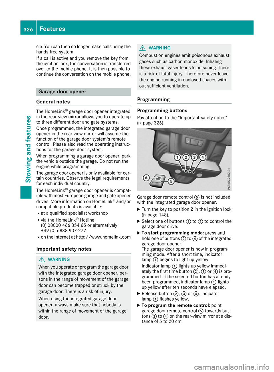
(Y page 326). Garage door remote control
Ais not included
with the integrated garage door opener.
X Turn the key to position 2in the ignition lock
(Y page 148).
X Select one of buttons ;to? to control the
garage door drive.
X To start programming mode: press and
hold one of buttons ;to? of the integrated
garage door opener.
The garage door opener is now in program-
ming mode. After a short time, indicator
lamp :begins to light up yellow.
Indicator lamp :lights up yellow immedi-
ately the first time button ;,=or? is pro-
grammed. If the selected button has already
been programmed, indicator lamp :lights
up yellow after ten seconds have elapsed.
X Release button ;,=or?. Indicator
lamp :flashes yellow.
X To program the remote control: point
garage door remote control Atowards but-
tons ;to? on the rear-view mirror at a dis-
tance of 5 to 20 cm. 326
FeaturesStowing and features
Page 330 of 397
X
Press and hold button Bon remote control
A until indicator lamp :lights up green.
When indicator lamp :lights up green: pro-
gramming is finished.
When indicator lamp :flashes green: pro-
gramming was successful. The next step is to synchronise the rolling code (Y page 327).
X Release button Bof remote control Aof the
garage door drive.
If indicator lamp :lights up red: repeat the
programming process for the corresponding
button on the rear-view mirror. When doing
so, vary the distance between remote control A and the rear-view mirror.
The required distance between remote con-
trol Aand the integrated garage door opener
depends on the garage door drive system.
Several attempts may be required. You
should test every position for at least
25 seconds before trying another position.
Synchronising the rolling code
Observe the "Important safety notes"
(Y page 326).
If the garage door system uses a rolling code,
you will also have to synchronise the garage
door system with the integrated garage door
opener in the rear-view mirror. To do this, you
will need to use the programming button on the door drive control panel. The programming but-
ton may be placed at different locations depend- ing on the manufacturer. It is usually located on
the door drive unit on the garage ceiling.
Familiarise yourself with the garage door drive
operating instructions, e.g. under "Program-
ming of additional remote controls", before car-
rying out the following steps.
Your vehicle must be within range of the garage
door or gate opener drive. Make sure that nei-
ther your vehicle nor any persons/objects are
present within the sweep of the door or gate.
X Turn the key to position 2in the ignition lock
(Y page 148).
X Get out of the vehicle.
X Press the programming button on the door
drive unit.
Usually, you now have 30 seconds to initiate
the next step. X
Get into the vehicle.
X Press previously programmed button ;,=
or ? of the integrated garage door opener
until the door closes.
The rolling code synchronisation is then com- plete.
Problems when programming
If you have problems when programming the
integrated garage door opener, please note the following:
R Check the transmitter frequency used by
garage door drive remote control Aand
whether it is supported. The transmitter fre-
quency can usually be found on the back of
remote control Afor the garage door drive.
R Replace the batteries in garage door remote
control A. This increases the likelihood that
garage door remote control Awill transmit a
strong and precise signal to the integrated
garage door opener in the rear-view mirror.
R When programming, hold remote control A
at varying distances and angles from but-
tons ;to? which you are programming. Try
various angles at a distance between 5and
20 cm or at the same angle but at varying
distances.
R If another remote control Ais available for
the same garage door drive, perform the pro-
gramming steps again using this remote con- trol A. Before performing these steps, make
sure that new batteries have been fitted in
garage door drive remote control A.
R Note that some remote controls transmit only
for a limited period (the indicator lamp on theremote control goes out). Press button Bon
remote control Aagain before transmission
ends.
R Align the aerial cable of the garage door
opener unit. This can improve signal recep-
tion/transmission.
Opening or closing the garage door Once programmed, the integrated garage door
opener will assume the function of the garage
door system's remote control. Please also read
the operating instructions for the garage door
system. Features
327Stowing and features Z
Page 331 of 397
X
Turn the key to position 2in the ignition lock
(Y page 148).
X Press button ;,=or? which you have
programmed to operate the garage door.
Garage door system with a fixed code: indi-
cator lamp :lights up green.
Garage door system with a rolling code: indi-
cator lamp :flashes green.
The transmitter will transmit a signal for as
long as the button is pressed. The transmis-
sion is halted after a maximum of ten seconds
and indicator lamp :lights up yellow.
X Press button ;,=or? again if necessary.
Clearing the memory Make sure that you clear the memory of the
integrated garage door opener before selling the vehicle.
X Turn the key to position 2in the ignition lock
(Y page 148).
X Press and hold buttons ;and ?.
The indicator lamp initially lights up yellow
and then green.
X Release buttons ;and ?.
The memory of the integrated garage door
opener in the rear-view mirror is cleared.
Frequencies Europe
Country Radio type approval num-
ber
Frequency range (MHz)
AD (Andorra) 20 July 2005
MHz: 27, 30, 40, 433, 868
AT (Austria) Article 6 of Directive
1999/5/EC R&TTE 18 May
05
MHz: 27, 40, 433, 868
BE (Belgium) Article 6 of Directive
1999/5/EC R&TTE 18 May
05
MHz: 27, 40, 433, 868
BG (Bulgaria) Article 6 of Directive
1999/5/EC R&TTE 12 April
07
MHz: 27, 40, 433, 868 Country Radio type approval num-
ber
Frequency range (MHz)
CH (Switzer-
land) Article 6 of Directive
1999/5/EC R&TTE 14357 27
May 05
MHz: 27, 40, 433, 868 CY (Cyprus) Article 6 of Directive
1999/5/EC R&TTE 5 May 05
MHz: 27, 40, 433, 868 CZ (Czech
Republic) General Licence GL-30/R/
2000 Reg No. 844 13 May 05
MHz: 27, 40, 433 DK (Den-
mark) Article 6 of Directive
1999/5/EC R&TTE 20 April
05
MHz: 27, 40, 433, 868
DE (Ger-
many) Article 6 of Directive
1999/5/EC R&TTE 7519301
29 April 05
MHz: 27, 40, 433, 868
EE (Estonia) Article 6 of Directive
1999/5/EC R&TTE 11 May
05
MHz: 27, 40, 433, 868
ES (Spain) 000438/2005,
000439/2005,
000440/2005
000441/2005,
000445/2005,
000446/2005
000447/2005
MHz: 27, 40, 433, 868
FI (Finland) Article 6 of Directive
1999/5/EC R&TTE 10668 13
May 05
MHz: 27, 40, 433, 868 FR (France) Article 6 of Directive
1999/5/EC R&TTE 10668 13
May 05
MHz: 27, 30, 40, 433, 868 GI (Gibraltar) Article 6 of Directive
1999/5/EC R&TTE 10668 13
May 05 (UK)
MHz: 27, 40, 418, 433, 868 328
FeaturesStowing and features
Page 335 of 397
Engine compartment
Bonnet
Important safety notes G
WARNING
An unlocked bonnet may open up when the
vehicle is in motion and block your view. There is a risk of an accident.
Never unlock the bonnet when driving. Before
every trip, ensure that the bonnet is locked. G
WARNING
When being opened and closed, the bonnet
may suddenly fall into the closed position.
There is a risk of injury to persons in the range of movement of the bonnet.
Open and close the bonnet only when nobody
is in the range of movement. G
WARNING
If you open the bonnet while the engine is
overheating or while there is a fire in the
engine compartment, you could come into
contact with hot gases or other leaking ser-
vice products. There is a danger of injury.
Allow an overheating engine to cool down
before opening the bonnet. If there is a fire in the engine compartment, leave the bonnet
closed and notify the fire brigade. G
WARNING
There are moving components in the engine
compartment. Certain components may con-
tinue to move or suddenly move again even
after the ignition has been switched off, e.g.
the radiator fan. There is a risk of injury.
If you have to carry out work in the engine
compartment:
R switch off the ignition
R never touch the dangerous areas surround-
ing moving components, e.g. the rotation
area of the fan R
remove jewellery and watches
R keep items of clothing and hair, for exam-
ple, away from moving parts. G
WARNING
The ignition system and the fuel injection sys- tem operate with a high voltage. If you touch
the live components, you could receive an
electric shock. There is a danger of injury.
Never touch components of the ignition sys-
tem or the fuel injection system when the
ignition is switched on.
Active bonnet (pedestrian protection) Operating principle
! An active bonnet that had been triggered
must be repaired at a qualified specialist
workshop. The active bonnet function will
then be available again. The additional pedes- trian protection provided by the active bonnet will then be restored.
i The active bonnet is available only for cer-
tain countries. It is available for all models,
except for the Mercedes-AMG GLS 63.
The active bonnet can reduce the risk of injury to
pedestrians in certain accident situations. Rais- ing the active bonnet increases the clearance tohard components, such as the engine.
If the active bonnet has been triggered, it is
raised at the rear in the area around the hinge byapproximately 100 mm. The active bonnet is
triggered by pyrotechnics.
For the drive to the workshop, reset the trig-
gered active bonnet yourself. After being reset,
the active bonnet rests in the area of the hinges
on the seals, and the hinges do not engage. For this reason, we recommend that you do not
exceed a maximum permissible speed of
130 km/h on the way to the workshop. If the
active bonnet has been triggered, pedestrian
protection may be limited. 332
Engine compartmentMaintenance and care
Page 336 of 397
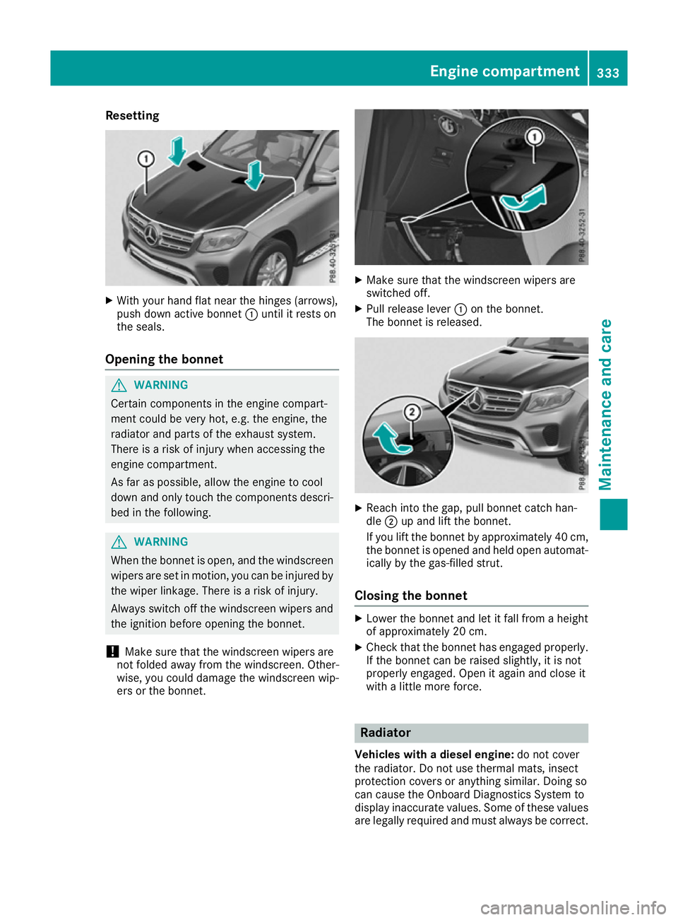
Resetting
X
With your hand flat near the hinges (arrows),
push down active bonnet :until it rests on
the seals.
Opening the bonnet G
WARNING
Certain components in the engine compart-
ment could be very hot, e.g. the engine, the
radiator and parts of the exhaust system.
There is a risk of injury when accessing the
engine compartment.
As far as possible, allow the engine to cool
down and only touch the components descri- bed in the following. G
WARNING
When the bonnet is open, and the windscreen wipers are set in motion, you can be injured by
the wiper linkage. There is a risk of injury.
Always switch off the windscreen wipers and
the ignition before opening the bonnet.
! Make sure that the windscreen wipers are
not folded away from the windscreen. Other-
wise, you could damage the windscreen wip-
ers or the bonnet. X
Make sure that the windscreen wipers are
switched off.
X Pull release lever :on the bonnet.
The bonnet is released. X
Reach into the gap, pull bonnet catch han-
dle ;up and lift the bonnet.
If you lift the bonnet by approximately 40 cm, the bonnet is opened and held open automat-
ically by the gas-filled strut.
Closing the bonnet X
Lower the bonnet and let it fall from a height
of approximately 20 cm.
X Check that the bonnet has engaged properly.
If the bonnet can be raised slightly, it is not
properly engaged. Open it again and close it
with a little more force. Radiator
Vehicles with a diesel engine: do not cover
the radiator. Do not use thermal mats, insect
protection covers or anything similar. Doing so
can cause the Onboard Diagnostics System to
display inaccurate values. Some of these values are legally required and must always be correct. Engine compartment
333Maintenance and care Z
Page 338 of 397
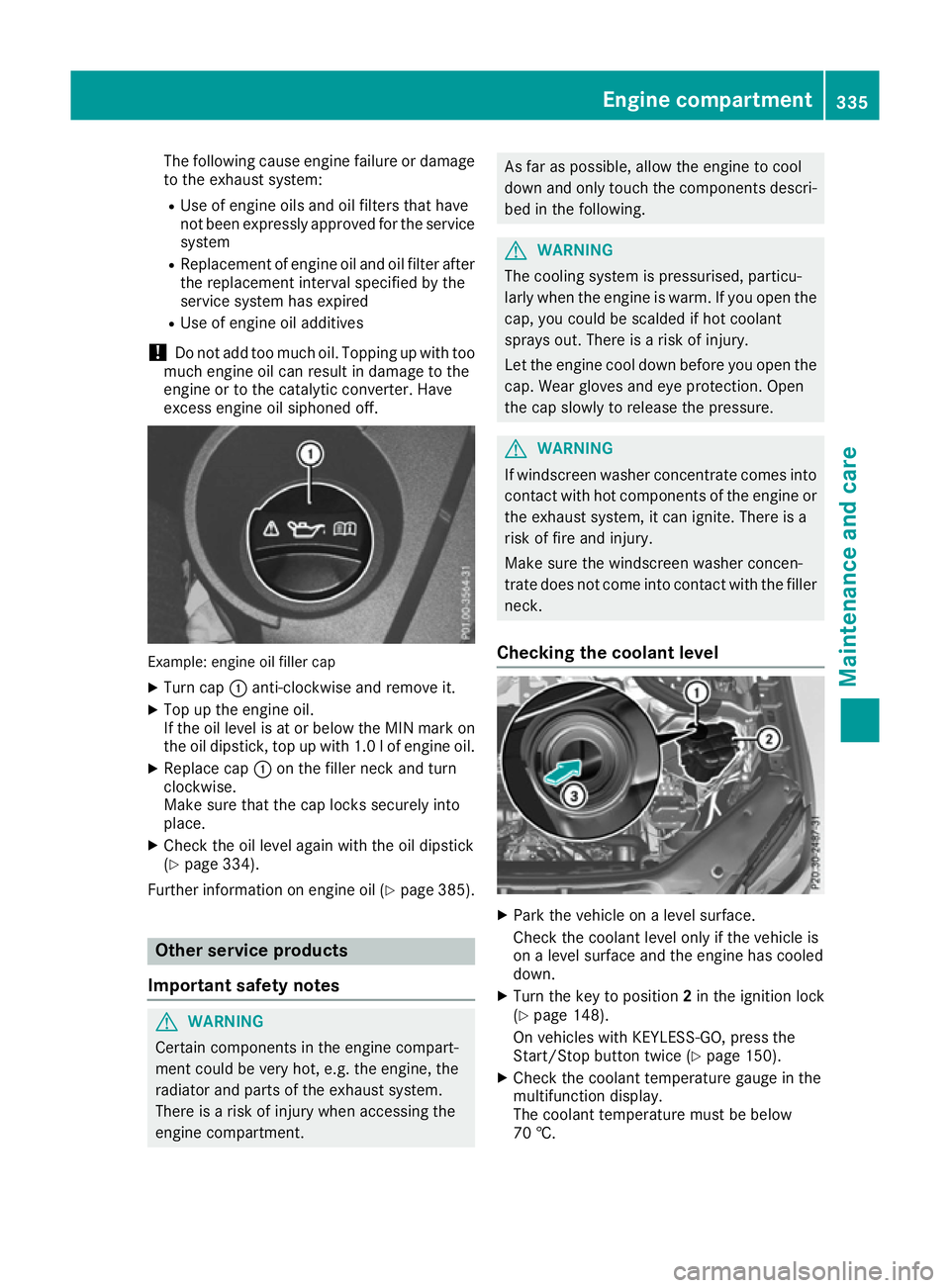
The following cause engine failure or damage
to the exhaust system:
R Use of engine oils and oil filters that have
not been expressly approved for the service
system
R Replacement of engine oil and oil filter after
the replacement interval specified by the
service system has expired
R Use of engine oil additives
! Do not add too much oil. Topping up with too
much engine oil can result in damage to the
engine or to the catalytic converter. Have
excess engine oil siphoned off. Example: engine oil filler cap
X Turn cap :anti-clockwise and remove it.
X Top up the engine oil.
If the oil level is at or below the MIN mark on
the oil dipstick, top up with 1.0 lof engine oil.
X Replace cap :on the filler neck and turn
clockwise.
Make sure that the cap locks securely into
place.
X Check the oil level again with the oil dipstick
(Y page 334).
Further information on engine oil (Y page 385).Other service products
Important safety notes G
WARNING
Certain components in the engine compart-
ment could be very hot, e.g. the engine, the
radiator and parts of the exhaust system.
There is a risk of injury when accessing the
engine compartment. As far as possible, allow the engine to cool
down and only touch the components descri-
bed in the following. G
WARNING
The cooling system is pressurised, particu-
larly when the engine is warm. If you open the cap, you could be scalded if hot coolant
sprays out. There is a risk of injury.
Let the engine cool down before you open the
cap. Wear gloves and eye protection. Open
the cap slowly to release the pressure. G
WARNING
If windscreen washer concentrate comes into contact with hot components of the engine or
the exhaust system, it can ignite. There is a
risk of fire and injury.
Make sure the windscreen washer concen-
trate does not come into contact with the filler neck.
Checking the coolant level X
Park the vehicle on a level surface.
Check the coolant level only if the vehicle is
on a level surface and the engine has cooled
down.
X Turn the key to position 2in the ignition lock
(Y page 148).
On vehicles with KEYLESS-GO, press the
Start/Stop button twice (Y page 150).
X Check the coolant temperature gauge in the
multifunction display.
The coolant temperature must be below
70 †. Engine compartment
335Maintenance and care Z
Page 339 of 397
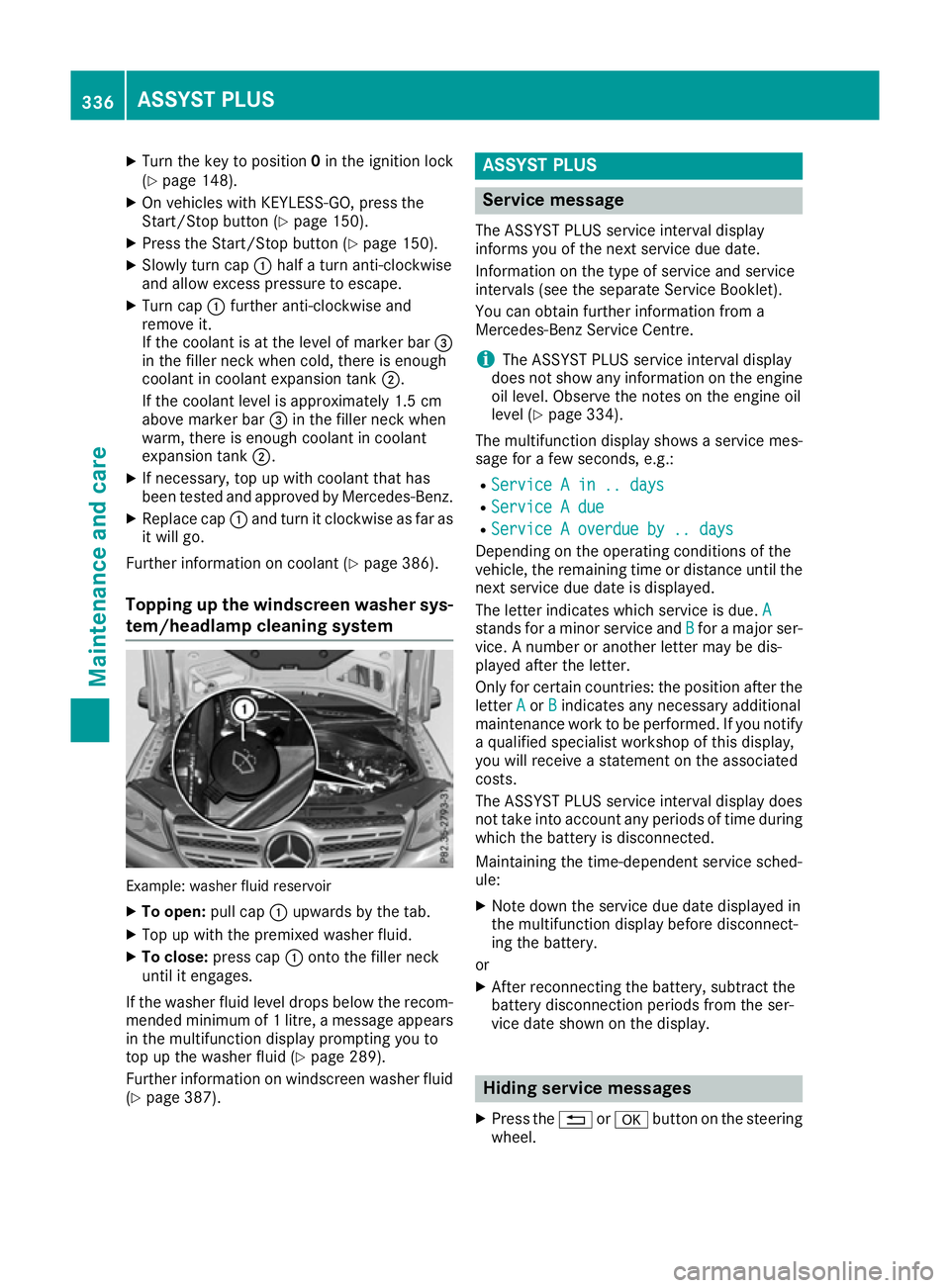
X
Turn the key to position 0in the ignition lock
(Y page 148).
X On vehicles with KEYLESS-GO, press the
Start/Stop button (Y page 150).
X Press the Start/Stop button (Y page 150).
X Slowly turn cap :half a turn anti-clockwise
and allow excess pressure to escape.
X Turn cap :further anti-clockwise and
remove it.
If the coolant is at the level of marker bar =
in the filler neck when cold, there is enough
coolant in coolant expansion tank ;.
If the coolant level is approximately 1.5 cm
above marker bar =in the filler neck when
warm, there is enough coolant in coolant
expansion tank ;.
X If necessary, top up with coolant that has
been tested and approved by Mercedes-Benz.
X Replace cap :and turn it clockwise as far as
it will go.
Further information on coolant (Y page 386).
Topping up the windscreen washer sys- tem/headlamp cleaning system Example: washer fluid reservoir
X To open: pull cap:upwards by the tab.
X Top up with the premixed washer fluid.
X To close: press cap :onto the filler neck
until it engages.
If the washer fluid level drops below the recom- mended minimum of 1 litre, a message appears in the multifunction display prompting you to
top up the washer fluid (Y page 289).
Further information on windscreen washer fluid
(Y page 387). ASSYST PLUS
Service message
The ASSYST PLUS service interval display
informs you of the next service due date.
Information on the type of service and service
intervals (see the separate Service Booklet).
You can obtain further information from a
Mercedes-Benz Service Centre.
i The ASSYST PLUS service interval display
does not show any information on the engine oil level. Observe the notes on the engine oil
level (Y page 334).
The multifunction display shows a service mes-
sage for a few seconds, e.g.:
R Service A in .. days Service A in .. days
R Service A due
Service A due
R Service A overdue by .. days
Service A overdue by .. days
Depending on the operating conditions of the
vehicle, the remaining time or distance until the
next service due date is displayed.
The letter indicates which service is due. A A
stands for a minor service and B
Bfor a major ser-
vice. A number or another letter may be dis-
played after the letter.
Only for certain countries: the position after the letter A
A or B
Bindicates any necessary additional
maintenance work to be performed. If you notify
a qualified specialist workshop of this display,
you will receive a statement on the associated
costs.
The ASSYST PLUS service interval display does
not take into account any periods of time during which the battery is disconnected.
Maintaining the time-dependent service sched-
ule:
X Note down the service due date displayed in
the multifunction display before disconnect-
ing the battery.
or
X After reconnecting the battery, subtract the
battery disconnection periods from the ser-
vice date shown on the display. Hiding service messages
X Press the %ora button on the steering
wheel. 336
ASSYST PLUSMaintenance and care
Page 340 of 397
Displaying service messages
X Switch the ignition on.
X Press the =or; button on the steering
wheel to select the Serv.
Serv.menu.
X Press the 9or: button to select the
ASSYST
ASSYST PLUS
PLUSsubmenu and confirm by press-
ing the abutton.
The service due date appears in the multi-
function display. Information about service
Resetting the ASSYST PLUS service
interval display !
If the ASSYST PLUS service interval display
has been inadvertently reset, this setting can
be corrected at a qualified specialist work-
shop.
Have service work carried out as described in the Service Booklet. This may otherwise lead
to increased wear and damage to the major
assemblies or the vehicle.
A qualified specialist workshop, e.g. a
Mercedes-Benz Service Centre, will reset the
ASSYST PLUS service interval display after the
service work has been carried out. You can also
obtain further information on maintenance
work, for example.
Special service requirements The prescribed service interval is based on nor-
mal operation of the vehicle. Service work will
need to be performed more often if the vehicle is
operated under arduous conditions or increased loads, for example:
R regular city driving with frequent intermediate
stops
R if the vehicle is primarily used to travel short
distances
R for frequent operation in mountainous terrain
or on poor road surfaces
R if the engine is often left idling for long periods
In these or similar operating conditions, have,
for example, the air filter, engine oil and oil filter changed more frequently. The tyres must be
checked more frequently if the vehicle is oper-
ated under increased loads. Further informationcan be obtained at a qualified specialist work-
shop, e.g. a Mercedes-Benz Service Centre. Driving abroad An extensive Mercedes-Benz Service network is
also available in other countries. You can obtain further information from any Mercedes-Benz
Service Centre. Care
General notes
H
Environmental note
Dispose of empty packaging and cleaning
cloths in an environmentally responsible man-
ner.
! For cleaning your vehicle, do not use any of
the following:
R dry, rough or hard cloths
R abrasive cleaning agents
R solvents
R cleaning agents containing solvents
Do not scrub.
Do not touch the surfaces or protective films
with hard objects, e.g. a ring or ice scraper.
You could otherwise scratch or damage the
surfaces and protective film.
! Do not park up your vehicle for a long period
of time immediately after cleaning, particu-
larly after cleaning the wheel rim with wheel
cleaner. Wheel cleaner may lead to increased corrosion of the brake discs and pads. You
should therefore drive for a few minutes after
cleaning. By heating up the brakes, the brake
discs and pads dry. The vehicle can then be
parked up for a long period of time.
Regular care of your vehicle is a condition for
retaining quality in the long term.
Use care products and cleaning agents recom-
mended and approved by Mercedes-Benz. Care
337Maintenance and care Z