2016 MERCEDES-BENZ G-CLASS SUV key
[x] Cancel search: keyPage 218 of 261
Allow an overheating engine to coo
ldown
before opening the bonnet. If ther eisafirein
the engine compartment, leav ethe bonnet
closed and notify the fir ebrigade.
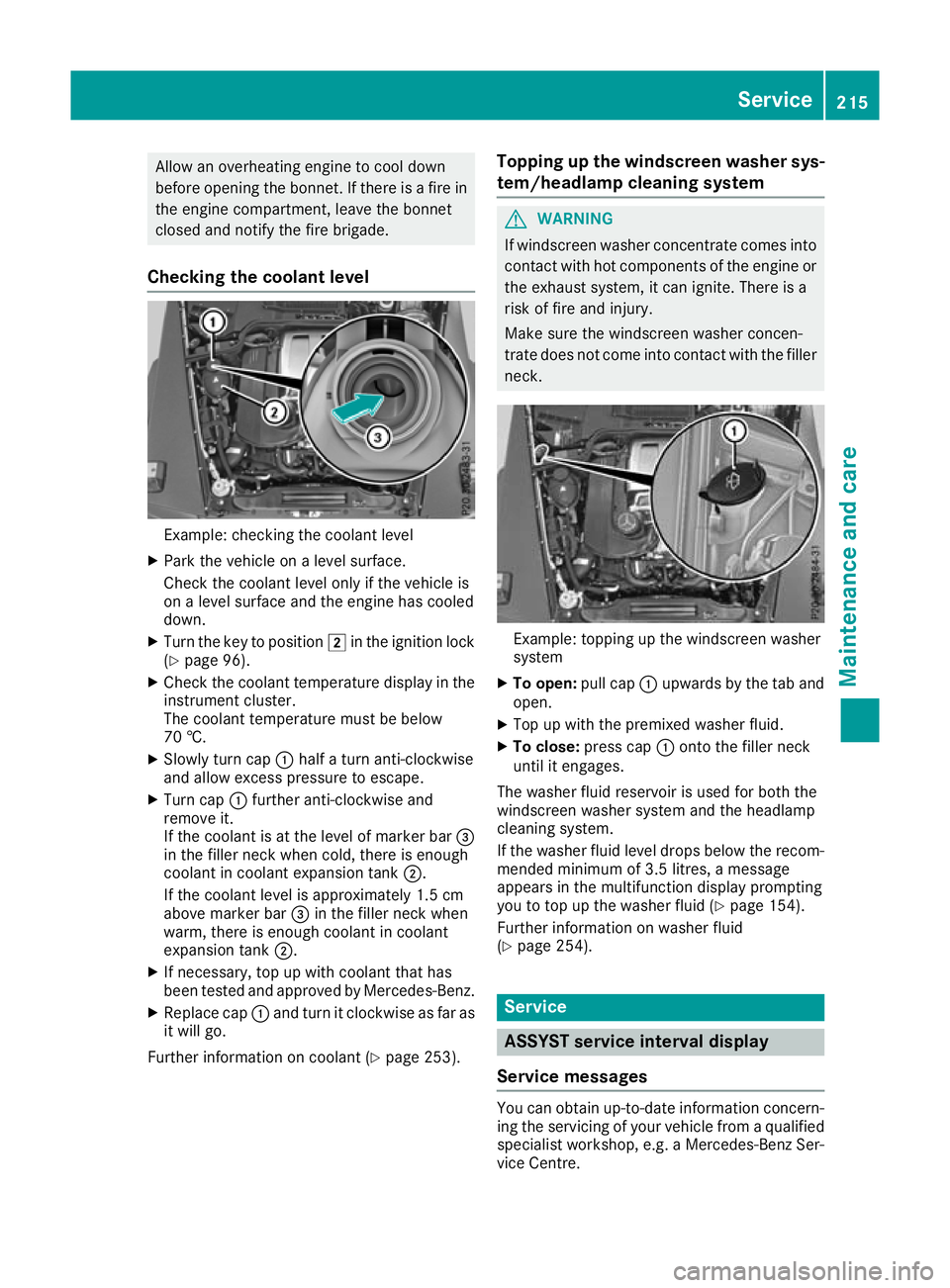
Checkin gthe coolant level Example: checking the coolant level
X Park the vehicl eonalevel surface.
Check the coolant level onl yifthe vehicl eis
on alevel surface and the engine ha scooled
down.
X Turn the key to position 2in the ignition lock
(Y page 96).
X Check the coolant temperatur edisplay in the
instrument cluster.
The coolant temperatur emustbeb elow
70 †.
X Slowl yturnc ap : half aturna nti-clockwise
and allo wexcess pressure to escape.
X Turn cap :furthe ranti-clockwise and
remove it.
If the coolant is at the level of marker bar =
in the fille rneck when cold, there is enough
coolant in coolant expansio ntank ;.
If the coolant level is approximately 1.5 cm
above marker bar =in the fille rneck when
warm, there is enoug hcoolant in coolant
expansio ntank ;.
X If necessary ,top up with coolant tha thas
been teste dand approved by Mercedes-Benz.
X Replace cap :and tur nitclockwise as fa ras
it will go.
Furthe rinformatio noncoolant (Y page 253). Topping up the windscreen washe
rsys-
tem/headlamp cleanin gsystem G
WARNING
If wind screen washer concentrate comes into
contact with hot components of the engine or
the exhaust system, it can ignite. There is a
risk of fire and injury.
Make sure the windscreen washer concen-
trate does not come into contact with the filler neck. Example: topping up the windscreen washer
system
X To open: pull cap:upwards by the tab and
open.
X Top up with the premixed washe rfluid.
X To close: press cap :onto the fille rneck
unti lite ngages.
The washe rfluid reservoi risusedf or both the
windscree nwashe rs ystem and the headlamp
cleaning system.
If the washe rfluid level drops belo wthe recom-
mended minimu mof3.5 litres ,amessage
appear sinthe multifunctio ndisplay prompting
yo utot op up the washe rfluid (Y page 154).
Furthe rinformatio nonwashe rfluid
(Y page 254). Service
ASSYST service interval display
Service messages Yo
uc an obtain up-to-dat einformation concern-
ing the servicin gofyour vehicle from aqualified
specialis tworkshop, e.g. aMercedes-Ben zSer-
vice Centre. Service
215Maintenance and care Z
Page 227 of 261
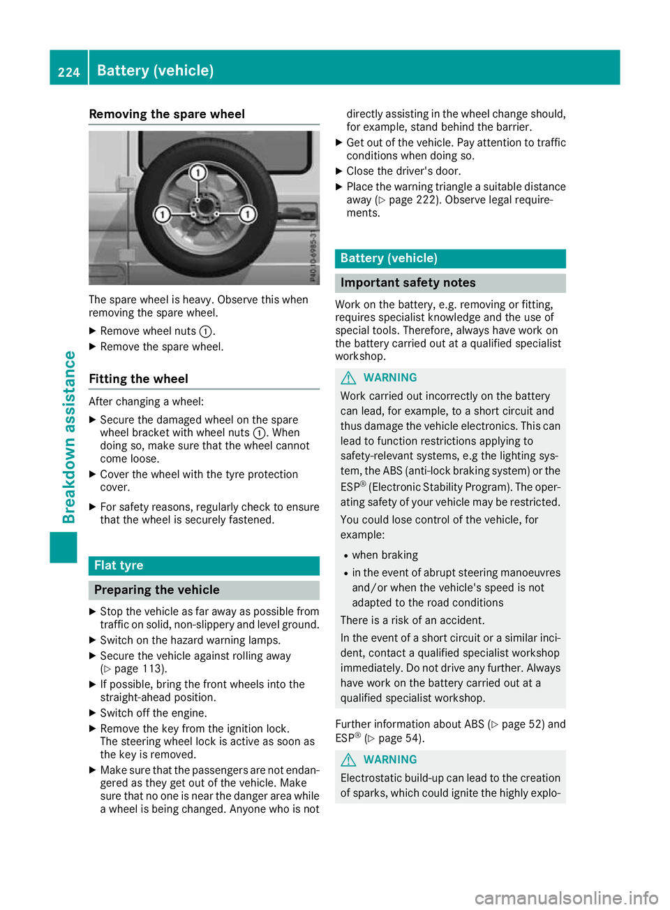
Removin
gthe spare wheel The spare wheel is heavy. Observ
ethis when
removing the spare wheel.
X Remove wheel nuts :.
X Remove the spare wheel.
Fitting the wheel After changing
awheel:
X Secure the damaged whee lonthe spare
whee lbracket with whee lnuts :.W hen
doing so, make sure tha tthe whee lcannot
come loose.
X Cover the whee lwitht he tyr eprotection
cover.
X For safety reasons ,regularly check to ensure
tha tthe whee lissecurel yfastened. Flat tyre
Preparing the vehicle
X Sto pthe vehicle as far away as possible from
traffic on solid, non-slippery and level ground.
X Switch on the hazard warning lamps.
X Secure the vehicle against rolling away
(Y page 113).
X If possible, bring the front wheels into the
straight-ahead position.
X Switch off the engine.
X Remove the key from the ignition lock.
The steering wheel lock is active as soon as
the key is removed.
X Make sure that the passengers are not endan-
gered as they get out of the vehicle. Make
sure that no one is near the danger area while
aw heel is being changed. Anyone who is not directly assisting in the wheel change should,
for example, stand behind the barrier.
X Get out of the vehicle. Pay attention to traffic
condition swhen doing so.
X Close the driver' sdoor.
X Place the warning triangle asuitable distance
away (Y page 222). Observe legal require-
ments. Batter
y(vehicle) Importan
tsafety notes
Wor kont hebattery, e.g. removing or fitting,
require sspecialist knowledge and th euse of
special tools. Therefore, always have wor kon
th eb attery carrie dout at aqualified specialist
workshop. G
WARNING
Work carried ou tincorrectly on the battery
can lead, for example, to ashort circui tand
thus damage the vehicl eelectronics. This can
leadtof unction restrictions applying to
safety-relevant systems ,e.g the lighting sys-
tem, the ABS (anti-lock braking system) or the
ESP ®
(Electronic Stability Program). The oper-
ating safety of yourv ehiclemay be restricted.
You coul dlose control of the vehicle, for
example:
R when braking
R in the event of abrupt steering manoeuvres
and/or when the vehicle's spee disnot
adapted to the road conditions
There is arisk of an accident.
In the event of ashort circui torasimilar inci-
dent, contact aqualified specialist workshop
immediately. Do not drive any further. Always have work on the battery carrie dout at a
qualified specialist workshop.
Further information about ABS (Y page52) and
ESP ®
(Y page5 4). G
WARNING
Electrostatic build-u pcan leadtot he creation
of sparks, which coul dignite the highly explo- 224
Battery (vehicle)Breakdown assistance
Page 229 of 261
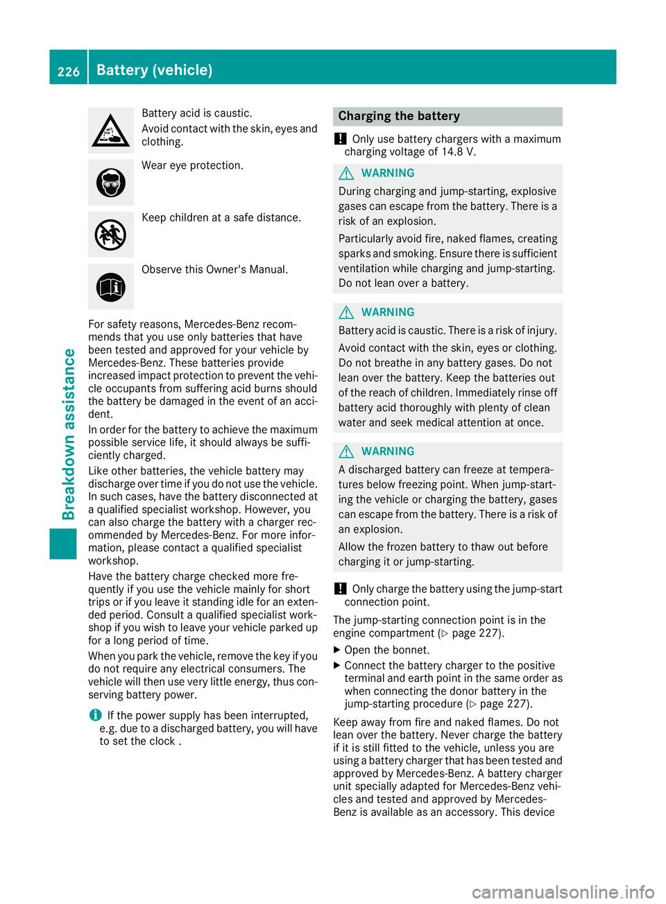
Battery aci
discaustic.
Avoid contact with the skin, eyes and clothing. Wea
reye protection. Keep children at
asafe distance. Observe this Owner's Manual.
For safety reasons, Mercedes-Benz recom-
mends that you use only batteries that have
been tested and approved for your vehicle by
Mercedes-Benz. These batteries provide
increased impact protection to prevent the vehi-
cle occupants from suffering acid burns should
the battery be damaged in the event of an acci- dent.
In order for the battery to achieve the maximumpossible service life, it should always be suffi-
ciently charged.
Like other batteries, the vehicle battery may
discharge over time if you do not use the vehicle.
In such cases, have the battery disconnected at aq uali fied specialist workshop .However, you
can also charge the battery with acharger rec-
ommended by Mercedes-Benz. For more infor-
mation, please contact aquali fied specialist
workshop.
Have the battery charge checked more fre-
quently if yo uuse the vehicle mainly for short
trips or if yo uleave it standing idl efor an exten-
ded period .Consul taq ualified specialist work-
shop if yo uwishtol eave your vehicle parked up
for along period of time.
Whe nyou park the vehicle, remove the key if you
do not require any electrica lconsumers. The
vehicle will then use very little energy, thus con- serving battery power.
i If the power supply has bee
ninterrupted,
e.g. du etoad ischarged battery, yo uwillh ave
to set the clock . Chargin
gthe battery
! Only use battery chargers wit
hamaximum
chargin gvoltage of 14.8 V. G
WARNING
During charging an djump-starting, explosive
gase scan escap efrom the battery .There is a
risk of an explosion.
Particularl yavoi dfire, naked flames, creating
sparks and smoking. Ensure there is sufficient
ventilation while charging and jump-starting.
Do not leano verabattery. G
WARNING
Battery acid is caustic. There is arisk of injury.
Avoid contact with the skin, eyesorc lothing.
Do not breathe in any battery gases. Do not
leano ver the battery .Keep the batterie sout
of the reach of children. Immediately rinse off
battery acid thoroughly with plenty of clean
water and seek medical attention at once. G
WARNING
Ad ischarged battery can freeze at tempera-
tures below freezing point. When jump-start-
ing the vehicl eorcharging the battery ,gases
can escap efrom the battery .There is arisk of
an explosion.
Allow the frozen battery to thaw out before
charging it or jump-starting.
! Only charge the battery using the jump-start
connection point.
The jump-starting connection point is in the
engine compartment (Y page227).
X Open the bonnet.
X Connect the battery charge rtothe positive
terminal and earth point in the same order as when connecting the donor battery in the
jump-starting procedure (Y page227).
Keep awayf rom fire and naked flames. Do not
leano ver the battery .Never charge the battery
if it is still fitted to the vehicle, unless you are
using abattery charge rthat has been tested and
approved by Mercedes-Benz. Abattery charger
unit speciallya dapted for Mercedes-Benz vehi-
cles and tested and approved by Mercedes-
Benz is available as an accessory. This device 226
Battery (vehicle)Breakdown assistance
Page 233 of 261
(30
x30c m). This will make othe rroad
users aware that avehicle is being towed.
R Only secure the tow cable to the towing
eyes or, if available, to the trailer tow hitch.
R Observ ethe brake lamps of the towing
vehicle while driving. Always maintain adis-
tance adistance so that the tow rope does
not sag.
R Do not use steel cables or chain stotow
your vehicle. You could otherwise damage
the vehicle.
! Do not use the trailer tow hitc
hfor recovery
or towing. Do not use the towin geye for
recovery. This could damage the vehicle. If in
doubt, have the vehicle recovered using a
crane.
! When towing, pull away slowly and
smoothly. If the tractive power is too high, the
vehicles could be damaged.
! Your vehicles is equipped with an automatic
transmission .Therefore, you must not have
the vehicle tow-started. The transmission
may otherwise be damaged.
Observ ethe legal requirementsine ach individ-
ual country when towing.
It is better to have the vehicle transported than
to have it towed.
If the transfer case can be shifted int othe Neu-
tral position, you can tow away the vehicle.
If the transfer case cannot be shifted int othe
Neutral position, you can tow away the vehicle
with one axle raised. Please bear the following in
mind:
R remov ethe propeller shaft from between the
transfer case and the rolling axle.
R turn the key to position 1in the ignition lock.
The battery must be connected and charged.
Otherwise, you:
R cannot turn the key to position 2in the igni-
tion lock
R cannot shift the automatic transmission to
position i To
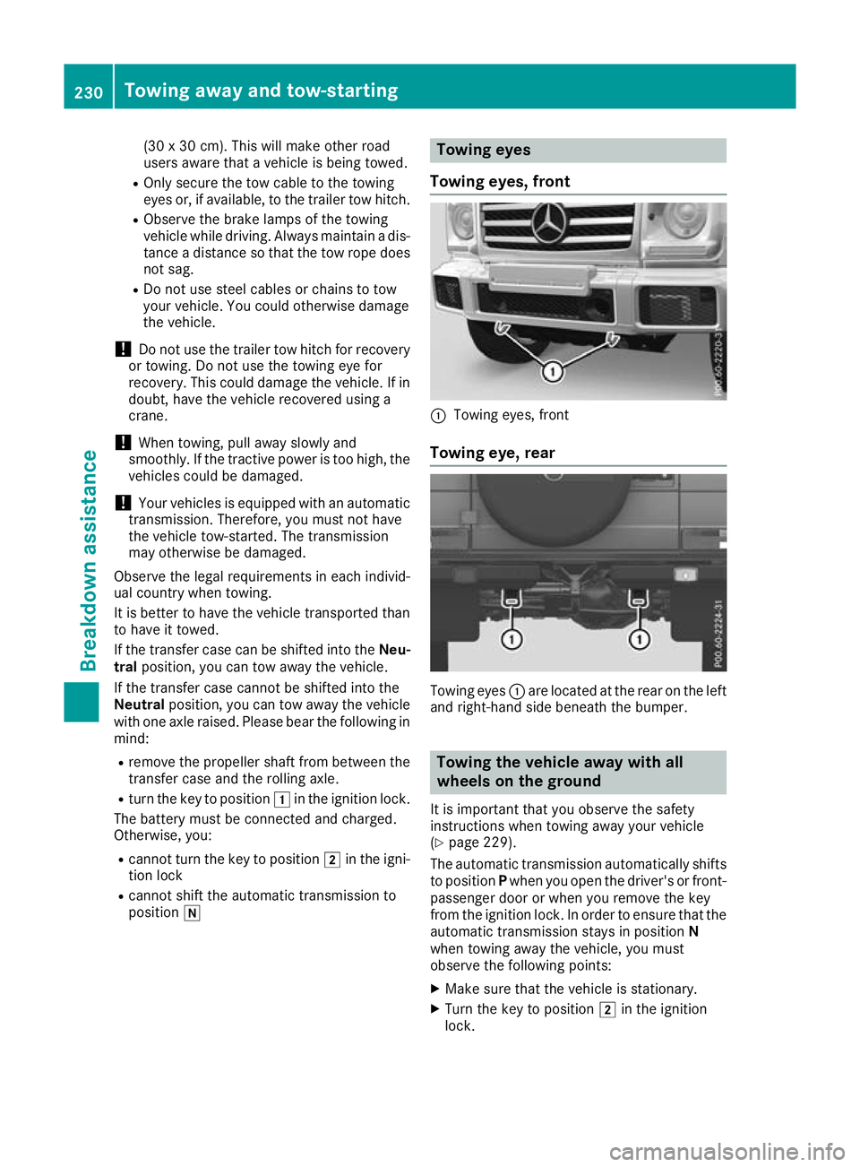
wing eyes
Towin geyes, front :
Towing eyes ,front
Towing eye, rear Towing eyes
:are located at the rear on the left
and right-hand side beneath the bumper. To
wing the vehicle away with all
wheels on the ground
It is important tha tyou observe the safety
instructions when towing away your vehicle
(Y page 229).
The automatic transmission automaticall yshifts
to position Pwhen yo uopenthe driver's or front-
passenge rdoororw heny ou remove the key
fro mt he ignition lock. In order to ensur etha tthe
automatic transmission stays in position N
when towing away the vehicle, yo umust
observe the following points:
X Make sure tha tthe vehicl eisstationary.
X Turn the key to position 2in the ignition
lock. 230
Towing away an
dtow-startingBreakdowna ssistan ce
Page 234 of 261
X
When the vehicle is stationary, depress the
brake pedal and keep it depressed.
X Shift the transfer case to position Neutral
(Y page 125).
X Shift the automatic transmission to position
N.
X Leave the key in position 2in the ignition
lock.
X Release the brake pedal.
X Release the parking brake.
X Switc hont he hazard warning lamps
(Y page 76).
In order to signal achange of direction when
towing the vehicle with the hazard warning
lamps switched on, use the combination switch
as usual. In this case, only the turn signals for
the desired direction flash. When you reset the
combination switch, the hazard warning lamps
start flashing again.
i The automatic transmission can only
change gear when the batter yhas sufficient
charge.
If you cannot shift the automatic transmission
to position N,the propeller shafts to the
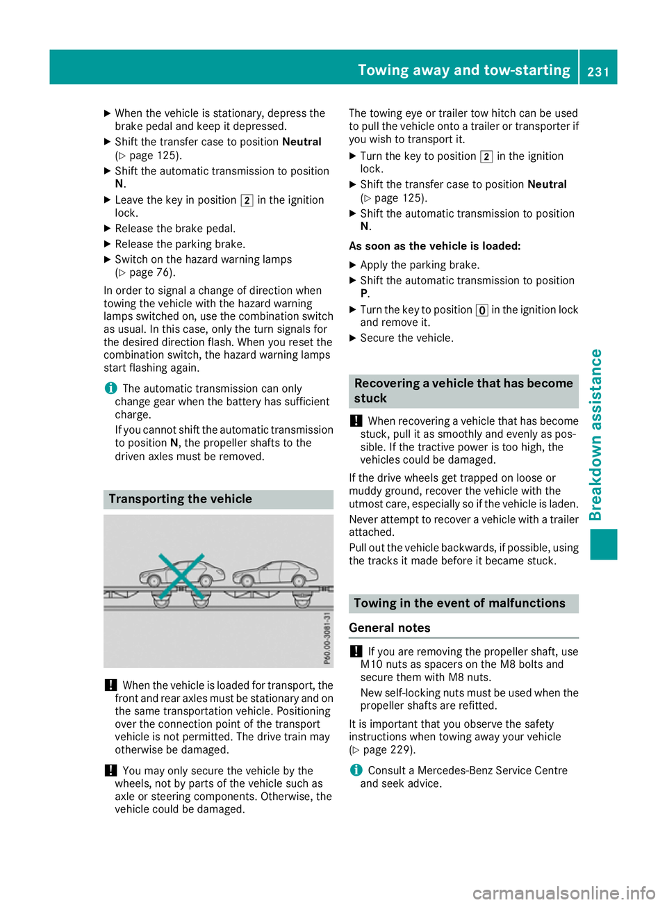
driven axles must be removed. Transporting thev
ehicle !
Whe
nthe vehicle is loadedf or transport, the
front and rear axles must be stationary and on the same transportation vehicle. Positioning
over the connection point of the transport
vehicle is not permitted. The drive train may
otherwise be damaged.
! You may only secure the vehicle by the
wheels, not by parts of the vehicle such as
axle or steering components. Otherwise, the
vehicle could be damaged. The towing eye or trailer tow hitch can be used
to pull the vehicle onto
atrailer or transporter if
you wish to transport it.
X Turn the key to position 2in the ignition
lock.
X Shift the transfer case to position Neutral
(Y page 125).
X Shift the automatic transmission to position
N.
As soon as the vehicle is loaded:
X Apply the parking brake.
X Shift the automatic transmission to position
P.
X Turn the key to position uin the ignition lock
and remove it.
X Secure the vehicle. Recovering
avehicle that has become
stuck
! Whe
nrecovering avehicl ethat ha sbecome
stuck, pull it as smoothly and evenly as pos-
sible .Ifthe tractive power is too high, the
vehicles could be damaged.
If the drive wheel sget trapped on loose or
muddy ground ,recover the vehicl ewitht he
utmost care ,especially so if the vehicl eisladen.
Neve rattempt to recover avehicl ewithat railer
attached.
Pull ou tthe vehicl ebackwards ,ifpossible ,using
the tracks it mad ebefore it became stuck. Towin
ginthe even tofm alfunctions
General notes !
If you are removing the propelle
rshaft, use
M10 nuts as spacers on the M8 bolts and
secure them with M8 nuts.
New self-locking nuts must be used when the propellers hafts are refitted.
It is important that you observe the safety
instructionsw hen towing awayy our vehicle
(Y page 229).
i Consult
aMercedes-Benz Service Centre
and seek advice. To
wing away and tow-starting
231Breakdown assis tance Z
Page 235 of 261
In th
eevent of damage to th eengine,
transmission or electrical system X
Shift th etransfer cas etoneutral position
Neutral (Ypage 125).
X Shif tthe automatic transmissio ntoposition
N.
In the even tofdamage to the transfer
case Have the propeller shafts between the axles and
the transfe rcase removed.
In the event of damage to the front axle Have the propeller shaft between the rea
raxle
and the transfe rcase removed.
The nhavet he vehicle towe dawayw itht he front
axl eraised.
In the event of damage to the rear axle Have the propeller shaft between the front axle
and the transfe rcase removed.
The nhavet he vehicle towe dwitht he rea raxle
raised and wheel rollers unde rthe front axle. Tow-start
ing( em ergency engine
starting)
! Do not tow-start vehicles with automatic
transmission. Yo ucould otherwis edamage
the automatic transmission.
Yo uc an find informatio non"Jump-starting"
under (Y page 227). Fuses
Importan
tsafety notes G
WARNING
If yo umanipulate, bridge or replace afaulty
fuse with afuse of ahigher amperage ,the
electric cables coul dbeoverloaded. This may
result in afire. There is arisk of an accident
and injury.
Always replace faulty fuses with specified new fuses of the correct amperage. The fuses in your vehicle disconnect fault
ycir-
cuits. If afuse blows, all the components in the
circuit and their functions will fail.
Blown fuses must be replaced with fuses of the same rating, which you can recognise by the
colour and fuse rating. The fuse ratings are listed
in the fuse allocation chart (Y page 233).
If the newly inserted fuse also blows, have the
cause traced and rectified at aqualified special-
ist workshop, e.g. aMercedes-Benz Service
Centre.
! Only use fuses that have been approved for
Mercedes-Benz vehicles and which have the
correc tfuse rating for the system concerned.
Otherwise, components or systems could be
damaged.
! Make sure that no moisture can enter the
fuse box when the cover is open.
! When closing the cover, make sure that it is
lying correctly on the fuse box. Moisture seep-
ing in or dirt could otherwise impair the oper-
ation of the fuses. Bef
orer eplacing afuse
Observ ethe important safety notes
(Y page 232).
X Switch off the engine.
X Switch off al lelectrical consumers.
X Remove the key from the ignition lock.
All indicator lamps on the instrument cluster
must be off.
X Secure the vehicl eagain st rolling away
(Y page 113).
The fuses are locate dinvarious fus eboxes:
R Main fus eboxon the front-passenger side of
the dashboard
R Fus eboxin the front-passenger footwell
R Fus eboxin the transmission tunnel
R Fus eboxin the luggage compartment
The fus ealloc ation chart and the spare fuses are
in the fus eboxon the dashboard on the front-
passenger side (Y page 233).
The fus eextractor is in the vehicl etool kit
(Y page 223). 232
FusesBreakdo
wn assis tance
Page 243 of 261

For further information on displaying this mes-
sage, refe rtothe "Checking the tyre pressure
electronically" section (Y page 240).
Important safety notes It is the driver's responsibility to set the tyre
pressure to the recommended cold tyre pres-
sure suitable for the operating situation
(Y page 238). Note that the correc ttyre pres-
sure for the current operating situation must
first be learnt by the tyre pressure monitor. If a
substantial loss of pressure occurs, the warning threshold for the warning message is aligned to
the learnt reference values. Restart the tyre
pressure monitor after adjusting to the cold tyre pressure (Y page 241). The current pressures
are saved as new reference values. This ensures that awarning message appears only if the tyre
pressure drops significantly.
The tyre pressure monitor does not warn you of
an incorrectly set tyre pressure. Observe the
notes on the recommended tyre pressure
(Y page 238).
The tyre pressure monitor is not abletow arn
you of asudden loss of pressure, e.g. if the tyre
is penetrated by aforeign object. In this event,
bring the vehicle to ahalt by braking carefully.
Avoid abrupt steering manoeuvres.
The tyre pressure monitor has ayellow h
warning lamp on the instrument cluster for indi-
cating apressure loss or malfunction. Depend-
ing on how the warning lamp flashe sorlights up,
at yre pressure that is too low or amalfunction in
the tyre pressure monitor is indicated:
R if the h warning lamp is lit continuously,
the tyre pressure on one or more tyres is sig-
nificantly too low. The tyre pressure monitor
is not malfunctioning.
R if the h warning lamp flashe sfor around a
minute and then remains lit constantly, the
tyre pressure monitor is malfunctioning.
In addition to the hwarning lamp,am essage
appears in the multifunction display. Observe
the information on display messages
(Y page 150).
It may take up to ten minutes for amalfunction
of the tyre pressure monitor to be indicated .A
malfunction willbei ndicated by thehtyre
pressure warning lamp flashing for approx-
imatel yone minute and then remaining lit. When
the faulth as been rectified, the htyre pres-
sure warning lamp goes out after driving for a
few minutes. The tyre pressure values indicated by the on-
board computer may differ from those meas-
ured at
afilling station using apressure gauge.
The tyre pressures shown by the on-board com-
puter refer to those measured at sea level. At
high altitudes, the tyre pressure values indica-
ted by apressure gauge are higher than those
shown by the on-board computer. In this case,
do not reduce the tyre pressures.
The operation of the tyre pressure monitor can
be affected by interferenc efrom radio transmit-
ting equipment (e.g. cordless headphones, two- way radios) that may be being operated in or
near the vehicle.
Checking the tyrep ressureelectroni-
cally X
Make sure that the key is in position 2in the
ignition lock.
X Press the =or; button on the steering
wheel to select the Serv.
Serv. menu.
X Press the 9or: button to select
Tyre pressure
Tyre pressure.
X Press the abutton.
The multifunction display shows the current
tyre pressure of each wheel.
If the vehicle has been parked for over
20 minutes, the Tyre pressures will be Tyre pressures will be
displayed
displayed after a
after afew
fewminutes
minutes of
ofdriv‐
driv‐
ing
ing message appears.
After ateach-in period, the tyre pressure moni-
tor automaticallyd etects new wheels or new
sensors. As long as aclear allocation of the tyre
pressure valuestot he individual wheels is not
possible,t heTyre
Tyre pressure
pressure monitor
monitoractive
active
displaym essage is shown instead of the tyre
pressure display. The tyre pressures are already being monitored.
If as pare wheel is fitted, the system may con-
tinue to show the tyre pressure of the wheel that has been removed for afew minutes. Please
note that in this case, the value displayed for the
replaced wheel does not indicate the current
tyre pressure of the spare wheel.
Warning messages of the tyre pressure monitor If the tyre pressure monitor detects
apressure
loss in one or more tyres, awarning messag eis
shown on the multifunction display. The yellow
h tyre pressure warning lamp then lights up. 240
Tyre pressureWheels and tyres
Page 244 of 261
R
If the Rectify tyre pressure
Rectify tyre pressure message
appears in the multifunction display, the tyre
pressure in at least one tyre is too low. The
tyre pressure must be corrected when the
opportunity arises.
R If the Check Check tyre(s)
tyre(s) message appears in the
multifunction display, the tyre pressure in at
least one tyre has droppe dsignificantly. The
tyres must be checked.
R If the Warning tyre defect Warning tyre defect message
appears in the multifunction display, the tyre
pressure in at least one tyre has droppe dsud-
denly.T he tyres must be checked.
Observe the instructions and safety notes in the display messages in the "Tyres" section
(Y page 150).
If the positio nofthe wheelsont he vehicle is
changed, the tyre pressures may be displayedin the wrong positions for ashort time. After afew
minutes of driving, this is rectified and the tyre
pressures are displayedint he correct positions.
Restarting the tyre pressure monitor When you restart the tyre pressure monitor, all
existing warning messages are deleted and the
h
warning lamp goes out. The monitor uses
the currently set tyre pressures as the reference valuesf or monitoring. In most cases, the tyre
pressure monitor will automatically detect the
new reference values after you have changed
the tyre pressure. However, you can also set
reference values manually as described here.
The tyre pressure monitor then monitors the
new tyre pressure values.
X Use the table on the inside of the fuel filler flap
to ensure that the tyre pressure is set cor-
rectly in all four tyres for the curren toperating
conditions.
Observe the notes on tyre pressure
(Y page 238).
X Make sure that the key is in position 2in the
ignition lock.
X Press the =or; button on the steering
wheel to select the Serv.
Serv. menu.
X Press the 9or: button to select
Tyre pressure Tyre pressure .
X Press the abutton.
The multifunction display shows the current
tyre pressure for each tyre or the Tyre
Tyre pres‐
pres‐ sures
sures
will
willbe
bedisplayed
displayed after a
after afew
few
minutes of driving
minutes of driving message appears.
X Press the :button.
The Use
Use current
current pressures
pressures as
asnew
new ref‐
ref‐
erence
erence values
valuesmessage appears in the mul-
tifunction display.
If you wish to confirm the restart:
X Press the abutton.
The Tyre
Tyre press.
press. monitor
monitor restarted
restarted mes-
sage appears in the multifunction display.
After you have driven for afew minutes, the
system checks whether the current tyre pres-
sures are within the specified range. The new tyre pressures are then accepted as refer-
ence valuesa nd monitored.
If you wish to cancelt he restart:
X Press the %button.
The tyre pressure valuess tored at the last
restart will continue to be monitored.
Radio type approval for the tyre pres-
sure monitor country Radi
otype approva lnumber Argentina Schrader GG4
Numero de Registro CNC:
H-12338
Brazil see below
Abu
Dhabi,
Dubai,
United
Arab Emi-
rates TRA
REGISTERED NO:
ER0099792/12.
DEALER NO: DA0047074/10
European
Union Hereby, Schrader Electronics
Ltd., declare
sthat this TPM Sisin
compliance with the essential
requirements and other provi-
sions of directive 1999/5/EC.
The declaration of conformity
may be consulted at emcteam@
schrader.co.uk Tyre pressure
241Wheels and tyres Z