Page 65 of 82

122 || 123
HANDLING THE UNEXPECTED
HANDLING THE UNEXPECTED
Replacing the Flat Tire
1. remove the wheel nuts and flat tire.
2. Mount the compact spare tire. replace the
wheel nuts, and lightly tighten them.
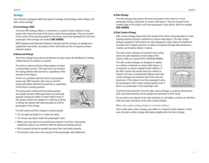
3. Lower the vehicle and remove the jack. Tighten
the wheel nuts in the order indicated in the
image. Go around, tightening the nuts, two to
three times in this order. Do not overtighten the
wheel nuts.
Models with wheel covers: Make sure the wire
support ring is hooked into the clips around the
edge of the wheel cover.
Align the valve mark on the wheel cover to the
tire valve on the wheel, then install the wheel
cover.
If you drive with the spare tire installed, the low tire pressure/TPMS i\
ndicator
appears. The indicator stays on until a regular tire is installed.
spilC
spilC
Valve mark
Storing the Flat Tire
1. remove the center cap, if necessary.
2. open the trunk. Place the flat tire face down in
the spare tire well.
3. remove the spacer cone from the wing bolt, flip
it over, and insert it back on the bolt. Secure the
flat tire with the wing bolt.
Models with wheel covers: Make sure the wire
support ring is hooked into the clips around the
edge of the wheel cover.
4. Securely put the jack and wheel nut wrench back
in the tool case. Store the case in the trunk.
Loose items can fly around the interior in a crash and can seriously i\
njure the
occupants.
Store the wheel, jack, and tools securely before driving.
WARNING
Spacer cone Wing bolt
For
compact
spare tireFor full -
size tire
Tire valv e
Wire support rin g
Page 66 of 82

124 || 125
HANDLING THE UNEXPECTED
HANDLING THE UNEXPECTED
Fuse Locations
If any electrical devices are not working, turn the vehicle off and chec\
k to see if any
applicable fuse is blown. Fuse locations are shown on the fuse box cover\
. Locate the
fuse in question by the fuse number and box cover number.
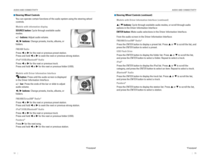
Engine Compartment Fuse Box
Located under the hood near the battery. Push the tabs to open the box.
*if equipped
Circuit ProtectedAmps
1
Passenger’s Power Seat*/
Rear Seat Heaters*(60 A)
Cooling Fan*1(30 A)Cooling Fan*2(50 A)��IG Main*3
�*430 A
�
Headlight High Beam Main30 ABattery125A
2
EPS70 A
IG Main 30
A*3
50A*4
Fuse Box Option*(40 A)
Fuse Box60AFront Wiper Moto r30A
Headlight Low Beam Main 30 A
3
Rear Defroster40 AStarter Motor*3
�*430A
�
Fuse Bo x40AABS/VSA Motor40AABS/VSA FS R40ABlower Motor40A
*1: 2.0L engine models
*2: 1.5L engine models
*3: Models with smart entry syste m
*4: Models without smart entry system
4
��
��
��
��
5Cooling Fan5A
6W asher15A7FI Main15A
8F I Sub1 5A
9 Stop Lights 10A
10 Injecto r
*2(15A )
11 LAF 5A
12 FI ECU 10A
13 Parking Lights 10A
14 Hazard1 5A
15 IG Coil 15A
16 Transmission
*5(1 5A )
17 Daytime Running Lights 10A
18 Back Up 10A
Circuit Protecte
d Amps
19 Audio 15A
20 Audio AMP*(30 A)
21 Interior Lights 10A
22 Front Fog Lights
*(15 A)
23 A/C Compressor*(10 A)
24 Horn 10A
25 Left Headlight Low Beam 10A
26 Right Headlight Low Beam 10A
27 VB ACT
*2(10 A)
28 Left Headlight High Beam 10A
29 Right Headlight High Beam 10A
30 ��
31 Rear Seat Heaters
*(15 A)
32 Passenger’s Power Seat
Sliding
*(20 A)
33 Passenger’s Power Seat
Reclining
*(20 A)
34 ��
35 � �
36 ��
Circuit Protected Amps
1 Passenger’s Power Seat*/
Rear Seat Heaters*(60 A)
Cooling Fan
*1(30 A)
Cooling Fan*2(50 A)
� �
IG Main
*3
�*430 A
�
Headlight High Beam Main 30A
Battery 125A
2 EPS
70A
IG Main 30
A
*3
50A*4
Fuse Box Option*(40 A)
Fuse Bo x6 0A
Front Wiper Moto r30A
Headlight Low Beam Main 30 A
3 Rear Defroster
40A
Starter Motor
*3
�*430 A
�
Fuse Bo x 40A
ABS/VSA Motor 40A
ABS/VSA FS R 40A
Blower Motor 40A
*1: 2.0L engine models
*2: 1.5L engine models
*3: Models with smart entry syste m
*4: Models without smart entry system
*5: Continuously variable transmission
models
4 ��
��
��
��
5 Cooling Fan 5A
6W asher1 5A
7 FI Main 15A
8F I Sub15A9Stop Lights10A
10 Injecto r*2(15A )11LAF5A
12 FI ECU 10A
13Parking Lights10 A
14 Hazard15A15IG Coil15A
16 Transmission*5(1 5A )17Daytime Running Lights10A
18 Back Up 10A
Circuit Protecte dAmps
19Audio15A
20 Audio AMP*(30 A)21Interior Lights10A
22 Front Fog Lights*(15 A)23A/C Compressor*(10 A)
24 Horn 10A
25Left Headlight Low Beam10A
26 Right Headlight Low Beam 10A
27VB ACT*2(10 A)
28 Left Headlight High Beam 10A
29Right Headlight High Beam10A
30��31Rear Seat Heaters*(15 A)
32 Passenger’s Power Seat
Sliding
*(20 A)
33Passenger’s Power Seat Reclining*(20 A)
34
��35��
36��
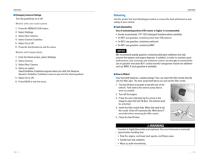
Interior Fuse Box
Located under the dashboard on the driver’s side.
*if equipped
Circuit ProtectedAmps1Accessory10 A
2�*1
Key Lock*2�
(5 A)
3��
4Front Sensor Camera*1
Transmission*2, *3(5A)
(10 A)
5Optio n10A6SRS Indicator10A7Meter10A8Fuel Pump15A
*3: Continuously variable transmission models
9AIRCON10A10��11Engine Control5A12Passenger Side Door Lock10A13Driver Side Rear Door Unloc k(10A )
14Rear Driver’s Side Power
Window(20A )
15Front Passenger’s Side
Power Windo w20A
16Door Lock20A
17Transmissio n*1, *3
Front Sensor Camera*2(10A )
(5 A)
18 ��
19 Moonroo f*(20A )
20 � �
21 ACG 10A
22 Daytime Running Lights 10A
23 � �
24 Front Sensor Camera
*(5 A)
25 Driver’s Door Lock 10A
26
Passen ger Side Door Unlock10A
27 Rear Passenger’s Side
Power Window (2
0A )
*1: Models with smart entry system
*2: Models without smart entry system 28
Driver’s Power Window 20A
29 Front Accessory Power
Socket 20
A
30 Smart Entry
*1
�*210
A
�
31 Driver’s Power Seat
Reclining
*(20 A)
32 Front Seat Heater
*(20 A)
33 Driver’s Power Seat Sliding*(20 A)
34 VSA/ABS 10A
35 SRS 10A
36 � �
37 ��
38 Driver Side Rear Door Lock (10 A)
39 Driver’s Door Unlock 10 A
Circuit Protecte
dAmps
Fuse label
Circuit Protected Amps
1 Accessory 10A
2 �
*1
Key Lock*2�
(5 A)
3 � �
4 Front Sensor Camera
*1
Transmission*2, *3(5
A)
(10 A)
5 Option 10A
6 SRS Indicator 10A
7 Meter 10A
8 Fuel Pump 15A
*3
: Continuously variable transmission models
9 AIRCON 10A
10 � �
11 Engine Control 5A
12 Passenger Side Door Lock 10A
13
Driver Side Rear Door Unloc k(10A )
14 Rear Driver’s Side Power
Window (2
0A )
15 Front Passenger’s Side
Power Windo w20
A
16 Door Lock 20A
17 Transmissio
n
*1, *3
Front Sensor Camera*2(10A )
(5 A)
18��19Moonroo f*(20A )20��21ACG10A22Daytime Running Lights10A23��24Front Sensor Camera*(5 A)25Driver’s Door Lock10A26Passen ger Side Door Unlock10A
27Rear Passenger’s Side
Power Window(20A )
*1: Models with smart entry system*2: Models without smart entry system
28Driver’s Power Window20 A
29 Front Accessory Power
Socket 20
A
30Smart Entry*1
�*210A
�
31 Driver’s Power Seat
Reclining
*(20 A)
32Front Seat Heater*(20 A)
33 Driver’s Power Seat Sliding*(20 A)34VSA/ABS10A
35 SRS 10A
36��
37��38Driver Side Rear Door Lock(10 A)
39 Driver’s Door Unlock 10 A
Circuit Protecte dAmps
Page 67 of 82

126 || 127
M
AINTENANCEHANDLING THE UNEXPECTED
Inspecting and Changing Fuses
1. Turn the vehicle off, including all lights and
accessories.
2. remove the fuse box cover.
3. Check the large fuse in the engine compartment.
If the fuse is blown, use a Phillips-head
screwdriver to remove the screws and replace
the fuse with a new one. reinstall the screws.
4. Inspect the small fuses in the engine
compartment and the vehicle interior.
If there is a burned out fuse, remove it with the
fuse puller and replace it with a new one.
Blown
fuse
Combined
fuse
Fuse puller
replacing a fuse with one that has a higher rating greatly increases the \
chances of
damaging the electrical system.
NOTICE
MAINTENANCE
Learn about basic maintenance that you can perform on the vehicle yourse\
lf, as well
as information about how to best maintain the vehicle.
Safety Precautions
Some of the most important safety precautions are listed below; however, we cannot
warn you of every conceivable hazard that can arise in performing mainte\
nance.
only you can decide whether or not you should perform a given task.
Maintenance Safety • To reduce the possibility of fire or explosion, keep cigarettes, sparks\
, and flames
away from the battery and all fuel-related parts.
• Never leave rags, towels, or other flammable objects under the hood.
• To clean parts, use a commercially available degreaser or parts cleaner, not
gasoline.
• Wear eye protection and protective clothing when working with the battery\
or
compressed air.
• Do not run the engine in confined spaces where carbon monoxide gas can\
accumulate.
Vehicle Safety
• The vehicle must be stationary, and parked on level ground with the parking
brake set and the engine off.
• Be aware that hot parts can burn you.
• Be aware that moving parts can injure you.
Improperly maintaining this vehicle or failing to correct a problem befo\
re
driving can cause a crash in which you can be seriously hurt or killed. \
Always follow the inspection and maintenance recommendations according
to the schedules in this guide.
WARNING
Failure to properly follow maintenance instructions and precautions can \
cause you to be seriously hurt or killed.
Always follow the procedures and precautions in this guide.
WARNING
Page 68 of 82

128 || 129
M
AINTENANCEMAINTENANCE
Maintenance Minder™
reminds you when indicated maintenance service is due.
Models with information display
When maintenance is due, the Maintenance Minder indicator comes on and a\
message appears on the display every time you turn the vehicle on. Press\
the TrIP
knob in the instrument panel to change displays (see page 28).
Models with Driver Information Interface
When maintenance is due, the system message indicator comes on and a mes\
sage
appears on the display every time you turn the vehicle on. Press the Dis\
play button
on the steering wheel to change displays (see page 29).
Maintenance Minder message
Maintenance
Minder indicator
Sub items
Main item
Maintenance Minder message
System message
indicator
Sub items
Main
item
U.S. models
Maintenance, replacement, or repair of emissions control devices and sys\
tems
may be done by any automotive repair establishment or individuals using \
parts
that are certified to EPA standards.
According to state and federal regulations, failure to perform maintenan\
ce on the
maintenance main items marked with # will not void your emissions warranties.
However, all maintenance services should be performed in accordance with the
intervals indicated by the Driver Information Interface.
Maintenance Minder Service Codes
These codes indicate what services are due on your vehicle.
U.S. models
*1: If a Maintenance Minder indicator does not appear more than 12 months af\
ter the display is reset, change the engine oil every year.
#: See information on maintenance and emissions warranty.
CODEMaintenance Main Items
A�Replace engine oi l*1
B�Replace engine oil*1 and oil �lter
�Inspect front and rear brakes
�Inspect these items:
• Tie rod ends, steering gear box, and boots
•S uspension components
• Driveshaft boots
• Brake hoses and lines (including ABS/VSA)
• All �uid levels and condition of �uids
• Exhaust system
#
•F uel lines and connection s#
*2:If you drive in dusty conditions, replace the air cleaner element every \
15,000 miles (24,000 km).*3:If you drive primarily in urban areas that have high concentrations of s\
oot in the air from industryand diesel-powered vehicles, replace the dust and pollen �lter every \
15,000 miles (24,000 km).*4:Driving in mountainous areas at very low vehicle speeds results in highe\
r transmission
temperatures. This requires transmission �uid changes more frequently\
than recommended by
the Maintenance Minder. If you regularly drive your vehicle under these conditions, have the
transmission �uid changed every 25,000 miles (40,000 km).
CODEMaintenance Sub Items
1
�Rotate tires
2�Replace air cleaner element*2
�Replace dust and pollen �lter*3
�Inspect drive belt
3
�Replace transmission �uid*4
4�Replace spark plug s
�Inspect valve clearance
5
�Replace engine coolant
7�Replace brake �uid*5
*5:If a Maintenance Minder indicator does not appear more than 36 months af\
ter the display for item 7 is reset, change the brake �uid every 3 years.
In addition:
• Inspect idle speed every 160,000 miles (256,000 km).
• Adjust the valves during services A, B, 1, 2, or 3 if they are noisy.
Page 69 of 82

130 || 131
M
AINTENANCEMAINTENANCE
*1: If a Maintenance Minder message does not appear more than 12 months afte\
r the display is
reset, change the engine oil every year.
*2: If you drive in dusty conditions, replace the air cleaner element every \
24,000 km (15,000 miles).
*3:
If you drive primarily in urban areas that have high concentrations of s\
oot in the air from industryand diesel-powered vehicles, replace the dust and pollen �lter every \
24,000 km (15,000 miles).
*4: Driving in mountainous areas at very low vehicle speeds results in highe\
r transmission
temperatures. This requires transmission �uid changes more frequently\
than recommended by
the Maintenance Minder. If you regularly drive your vehicle under these conditions, have the
transmission �uid changed every 40,000 km (25,000 miles).
*5: If a Maintenance Minder Indicator does not appear more than 36 months after the display for
item7 is reset, change the brake �uid every 3 years.#: See information on maintenance and emissions warranty.
CODEMaintenance Main Items
A�Replace engine oi l*1
0�Replace engine oil*1 and oil �lter
CODEMaintenance Sub Items
1
�Rotate tires
2�Replace air cleaner element*2
�Replace dust and pollen �lte r*3
�Inspect drive belt
3
�Replace transmission �uid*4
4�Replace spark plug s
�Inspect valve clearance
5
�Replace engine coolant
7�Replace brake �uid*5
9�Inspect front and rear brakes
�Inspect these items: •T ie rod ends, steering gearbox, and boots
•S uspension components
•D riveshaft boots
•B rake hoses and lines (including ABS/VSA)
•A ll �uid levels and condition of �uids
•E xhaust system
#
•Fuel lines and connections#
Canadian models
In addition:
• Inspect idle speed every 256,000 km (160,000 miles).
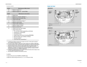
• Adjust the valves during services A, B, 1, 2, or 3 if they are noisy.Under the Hood
1.5 � engine model\
s
Brake �uid
(black cap)
Reserve \fank Washer �uid
(blue cap)
\bngine oil dips\fick\v
(orange) \bngine oil �ll cap Ba\f\fery
Reserve \fank cap
U.S. modelsWasher �uid
(blue cap)Canadian models
2.0 � engine model\/s
Brake/\flut\fh\b �uid
(Bla\fk \fap)
Reserve tank Washer �uid
(blue \fap) Engine oil dipsti\fk\/
(orange)
Engine oil �ll \fap Battery
Reserve tank \fap
*if equipped
Page 70 of 82

132 || 133
M
AINTENANCEMAINTENANCE
Opening the Hood
1. Park the vehicle on a level surface, and set the
parking brake.
2. Pull the hood release handle under the lower left
corner of the dashboard.
3. Push the hood latch lever in the center to the
right to release the lock mechanism, and open
the hood.
4. remove the support rod from the clamp using the
grip. Mount the support rod in the hood.
When closing, remove the support rod, and
stow it in the clamp, then gently lower the hood.
remove your hand at a height of approximately
12 inches (30 cm) and let the hood close.
Do not open the hood when the wiper arms are raised. The hood will strik\
e the
wipers, and may damage either the hood or the wipers.
NOTICE
Hood release handle
Pull
Lever
Support rodGrip
Clamp
Engine Oil
Park the vehicle on level ground, and wait approximately three minutes after turning
the engine off before you check the oil.
Checking the Oil
1. remove the dipstick (orange).
2. Wipe the dipstick with a clean cloth or paper
towel.
3. Insert the dipstick back all the way into its hole.
4. remove the dipstick again, and check the level.
It should be between the upper and lower marks.
Add oil if necessary.
1.5 � engine model\
s
Upper mark
Lower mark
1.5 � engine models
Upper mark
Lower mark
2.0 � engine models
2.0 � engine model\
s
Page 71 of 82

134 || 135
M
AINTENANCEMAINTENANCE
Recommended Engine Oil
•
Honda Genuine Motor Oil
• Premium-grade 0W-20 detergent oil with an API Certification Seal on the
container
This seal indicates the oil is energy conserving and
that it meets the American Petroleum Institute’s
latest requirements.
Use Honda Genuine Motor oil or another
commercial engine oil of suitable viscosity for the
ambient temperature as shown.
You may also use synthetic motor oil if it is labeled
with the API Certification Seal and is of the
specified viscosity grade.
Adding Oil
1. Unscrew and remove the engine oil fill cap.
2. Add oil slowly.
3. reinstall the engine oil fill cap, and tighten it
securely.
4. Wait for three minutes and recheck the engine oil
dipstick.
Ambient temperature
Engine oil
�ll cap
1.5 � engine models
Engine oil
�ll ca p
2.0 � engine models
Do not �ll the engine oil above the upper mark. Over�lling the engine oil can result
in leaks and engine damage.
NOTICE
Resetting the Engine Oil Life
If you change or replace the vehicle’s engine oil yourself, you must reset the
engine oil life.
Models with information display
1. Press the TrIP knob in the instrument panel until
the engine oil life appears in the display.
2. Press and hold the knob for 10 seconds or more,
until the display begins to blink.
3. Press and hold the knob for 5 seconds or more.
The engine oil life display returns to 100%.
Models with Driver Information Interface
Use the steering wheel buttons to make and enter selections (see page 2\
9).
1. Scroll to the Maintenance Minder screen, and
select it.
2. Press and hold the eNTer button for about 10
seconds to enter the reset mode.
3. Scroll to the maintenance item you want to reset
(or All Due Items), and select it.
Models with Display Audio
Use the touchscreen to make and enter selections.
1. From the HoMe screen, select Settings.
2. Select vehicle.
3. Select Maintenance Info.
4. Select Select reset Items.
5. Select an item on the list to reset.
Failure to reset the engine oil life after a maintenance service results\
in the
system showing incorrect maintenance intervals, which can lead to seriou\
s
mechanical problems.
NOTICE
Page 72 of 82

136 || 137
M
AINTENANCEMAINTENANCE
Engine Coolant
Park the vehicle on level ground. Check the reserve tank and the coolant\
level in the
radiator. We recommend Honda Long Life Antifreeze/Coolant Type 2.
Checking the Coolant
1. Check the amount of coolant in the reserve tank.
2. If the coolant level is below the MIN mark, add
the specified coolant until it reaches the MAX
mark.
3. Inspect the cooling system for leaks.
Adding Coolant
1. Make sure the engine and radiator are cool.
2. Turn the reserve tank cap counterclockwise and
relieve any pressure in the coolant system. Do
not push the cap down when turning.
3. Push down and turn the reserve tank cap
counterclockwise to remove it.
4. Pour coolant into the reserve tank until it reaches
the MAX mark.
5. Put the reserve tank cap back on, and tighten it
fully.
If temperatures consistently below −22°F (−30°C) are expec\
ted, the coolant
mixture should be changed to a higher concentration. Consult a dealer fo\
r details
for more information.
NOTICE
Reserve tank cap
1.5 � engine models
Reserve tank cap
2.0 � engine models
removing the radiator cap while the engine is hot can cause the coolant t\
o
spray out, seriously scalding you.
Always let the engine and radiator cool down before removing the radiato\
r
cap.
WARNING
Pour the fluid slowly and carefully so you do not spill any. Clean up any spills
immediately; they can damage components in the engine compartment.
NOTICE
MA X
MINReserve tan k
Window Washer Fluid
Check the amount of window washer fluid by looking
at the reservoir. If the washer fluid level is low, fill the
washer reservoir.
Pour the washer fluid carefully. Do not overflow the
reservoir.
Canadian models
If the washer fluid level is low, the washer level indicator or a message appears in
the Driver Information Interface.
Do not use engine antifreeze or a vinegar/water solution in the windshie\
ld washer
reservoir. Antifreeze can damage your vehicle’s paint. A vinegar/water solution
can damage the windshield washer pump.
NOTICE
Brake/Clutch* Fluid
The fluid level should be between the MIN and MAX marks on the side of\
the
reservoir. We recommend using Honda Heavy Duty Brake Fluid DOT 3.
Pour the fluid carefully.
If the fluid level is at or below the MIN mark, have a
dealer inspect for leaks or worn brake pads as soon as
possible.
The brake fluid reservoir is also used for your vehicle’s
clutch fluid. As long as you keep the brake fluid level
as instructed above, there is no need for checking the
clutch fluid level.
Brake fluid marked DoT 5 is not compatible with your vehicle’s braking system
and can cause extensive damage.
NOTICE
Brake reservoir
MINMAX
*if equipped