Page 217 of 396

215
C4-2_en_Chap07_infos-pratiques_ed02-2015
Before each use
Check that the towball is correctly fitted by verifying the following points:
- t he towball is correctly locked in place (position A),
-
t
he security key lock is on and the key removed; the locking wheel can no longer be
ope
rated,
-
t
he towball must no longer move at all in its carrier; try to shake it by hand.
During use
Never unlock the device when a trailer or load carrier is fitted to the towball.
N ever exceed the maximum authorised weight for the vehicle plus trailer (Gross Train
W
eight - GTW).
Before
driving, check the adjustment of the headlamp beam height.
For
more information on adjusting the headlamps, refer to the corresponding section.
After use
For journeys made without a trailer or load carrier, the trailer harness socket must be folded away, the towball removed and the blanking plug inserted in the carrier. This measure
a
pplies particularly if the towball could hinder visibility of the number plate or lighting.
7
Practical information
Page 218 of 396

216
C4-2_en_Chap07_infos-pratiques_ed02-2015
Fitting the towball
Remove the protective plug from the carrier and check the condition of the fixing system.
I
f necessary, clean the carrier with a brush or
clean
cloth.
Take
the towball from the storage bag.
Remove
the protective cover from the ball and
t
he protective cap from the locking wheel.
Stow
the plug, cover and cap in the
s
torage bag.
Check
that the towball is unlocked (position B).
I
f not, insert the key in the lock and turn the key
a
nti-clockwise to unlock the mechanism.Take
the towball in both hands; insert the end o
f the towball into the carrier by lifting it, then,
t
o ensure that it has correctly locked in place,
p
ull firmly down on the ball end of the towball.
The
locking wheel automatically turns a quarter
o
f a turn anti-clockwise, making a perceptible
c
lick; take care to keep your hands clear.Check
that the towball has correctly locked in p
lace (position A).
Turn
the key clockwise to lock the towball fixing
m
echanism.
Always
remove the key and keep it in a safe
p
lace.If
the key cannot be turned or removed,
t
his means that the towball is not fitted
c
orrectly; start the procedure again.
If
one of the locking conditions is not
m
et, start the procedure again.
In
all cases, if the marking remains
r
ed, do not use the towbar and contact
a
CITROËN dealer or a qualified
w
orkshop.
Practical information
Page 219 of 396
217
C4-2_en_Chap07_infos-pratiques_ed02-2015
Attach the trailer to the towball.
A ttach the cable on the trailer to the security
ring
located on the carrier.
Lower
the trailer harness socket carrier by
p
ulling down on the ring visible below the
b
u m p e r.
Remove
the protective cover from the socket
a
nd connect the trailer wiring harness.
Removing the towball
Disconnect the trailer harness from the socket on the carrier.
Detach
the cable on the trailer from the security
r
ing on the carrier.
Unhook
the trailer from the towball.
Return the trailer harness connector carrier to
the
folded position. Insert
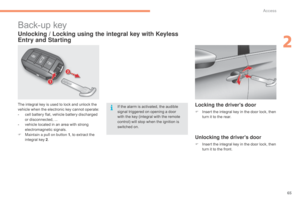
the key into the lock.
Turn the key anti-clockwise to unlock the
t
owball
f
ixing
m
echanism.
7
Practical information
Page 220 of 396
218
C4-2_en_Chap07_infos-pratiques_ed02-2015
Maintenance
Correct operation is only possible if the towball
and its carrier remain clean.
Before
cleaning the vehicle with a high pressure
j
et wash, the towbar harness socket carrier must
b
e folded away, the towball removed and the
b
lanking plug inserted in the carrier.
For
any work on the towbar, got to a CITROËN
d
ealer or a qualified workshop.
Refit the protective cover for the ball and the
protective
cover
for
the
locking
wheel.
Stow
the
towball
in
its
bag.
Refit
the
protective
blanking
plug
to
the
carrier.
Grasp
the
towball
firmly
with
one
hand;
with
t
he
other
hand,
press
and
turn
the
locking
w
heel clockwise
as
far
as
it
will
go.
Extract
the
towball
downward.
Be
ready
for
the
weight
of
the
towball
(
around
3.5
kg).
Risk
of
injury!
Practical information
Page 221 of 396

219
C4-2_en_Chap07_infos-pratiques_ed02-2015
Load reduction modeE nergy ec onomy m ode
Switching to economy mode
Once this period has elapsed, a message a
ppears in the screen indicating that the
v
ehicle has switched to economy mode and the
a
ctive functions are put on standby.
Exiting economy mode
These functions are reactivated automatically the next time the vehicle is driven.
F
I
n order to resume the use of these
f
unctions immediately, start the engine and
l
et it run for a few minutes.
The
time available to you will then be double
t
he period for which the engine is left running.
H
owever, this period will always be between
five
and thirty minutes.
System
which
manages
the
use
of
certain
f
unctions
according
to
the
level
of
charge
r
emaining
in
the
battery.
When
the
vehicle
is
being
driven,
the
load
r
eduction
function
temporarily
deactivates
c
ertain
functions,
such
as
the
air
conditioning,
t
he
heated
rear
screen...
The deactivated functions are reactivated
automatically
as
soon
as
conditions
permit. System
which
manages
the
period
of
use
of
certain
functions to conserve a sufficient level of
c
harge
in
the
battery.
After
the
engine
has
stopped,
you
can
still
use
functions such as the audio equipment, windscreen
w
ipers,
dipped
beam
headlamps, courtesy
lamps,
etc. for a maximum combined period of
t
hirty minutes.
A flat battery prevents the engine from
s
tarting.
For
more information on the 12 V
b
attery, refer to the corresponding
s
ection.
This
period
may
be
greatly
reduced
if
t
he
battery
is
not
fully
charged.
If
the
telephone
is
being
used
at
the
s
ame
time
with
the
touch
screen
tablet,
i
t
will
be
interrupted
after
10
minutes.
7
Practical information
Page 222 of 396

220
C4-2_en_Chap07_infos-pratiques_ed02-2015
Audio pre-equipment
Fitting an audio unit
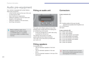
The audio unit is fitted in place of one of the
storage boxes located above the heating and
a
ir conditioning control panel.
F
U
nclip the storage box on each side using
a
screwdriver and pull out.
You will then have access to an aerial
coaxial
cable and two 8 -way connectors.
Then refer to the instructions provided with
your
audio unit.
Fitting speakers
It is possible to fit:
- 1 65 mm diameter speakers in the front
d
oors,
-
1
30 mm diameter speakers in the rear
d
oors,
-
2
2.5 mm diameter tweeters in the top of the
das
hboard.
Connectors
8-way connector (A)
A1: -
A2:
-
A3:
-
A4:
-
A5:
-
A6:
(+)
Ignition positive (in this case, the audio equipment only operates when the ignition is on)
A7: (+) Permanent
A 8: Earth
8-way connector (B)
B1:
(+) Rear right speaker
B2:
(-) Rear right speaker
B3:
(
+)
F
ront right speaker and tweeter
B 4:
(
-)
F
ront right speaker and tweeter
B5:
(+) Front left speaker and tweeter
B6:
(-) Front left speaker and tweeter
B7:
(+) Rear left speaker
B8:
(-) Rear left speaker
Never use a separate wire to connect
the
(+) of your audio equipment (risk of
d
ischarging of the battery).
Before
installing
a
radio
unit
or
s
peakers
in
your
vehicle,
contact
a
CITROËN
dealer
or
a
qualified
w
orkshop
to
obtain
a
suitable
wiring
har
ness.
Your
vehicle
is
equipped
with
certain
factory-
fitted
audio
equipment:
-
a d
ual-function aerial at the rear of the roof,
-
a
coaxial
aerial
cable,
-
b
asic interference suppression,
-
c
abling
for
speakers
in
the
front
doors
and
t
weeters in the dashboard,
-
c
abling
for
speakers
in
the
rear
doors,
-
t
wo
8 -way
connectors.
Practical information
Page 223 of 396
221
C4-2_en_Chap07_infos-pratiques_ed02-2015
Changing a wiper blade
Before removing a front
wiper blade
F Within one minute after switching off t
he ignition, operate the wiper stalk to
p
osition the wiper blades vertically on the
windscreen.
Removing
F Raise the corresponding wiper arm.
F U nclip the wiper blade and remove it.
Fitting
F Put the corresponding new wiper blade in p
lace and clip it.
F
F
old down the wiper arm carefully.
After fitting a front wiper
blade
F Switch on the ignition.
F O perate the wiper stalk again to park the
w
iper blades.
7
Practical information
Page 224 of 396

222
C4-2_en_Chap07_infos-pratiques_ed02-2015
Fitting roof bars
For safety reasons and to avoid damaging the roof, it is essential to use the transverse bars approved for your vehicle.
When
fitting roof bars, use only the four fixing
p
oints located in the roof frame. The points are
m
asked by the vehicle doors when closed.
The
roof bar fixings include a stud to be fitted to
t
he hole at each fixing point.
Observe
the fitting instructions and the
c
onditions of use in the guide supplied with the
b
ars. Maximum
load distributed over the roof
b
ars, for a load height not exceeding
4
0 cm (except bicycle carriers):
-
f
or roof bars with pads
at 90
mm:
50 kg,
-
f
or roof bars with pads
at 15 0
mm:
80 kg.
For
more information, contact a
C
ITROËN dealer or a qualified
w
orkshop.
If
the height exceeds 40 cm, adapt the
s
peed of the vehicle to the profile of the
road
to avoid damaging the roof bars
a
nd the fixings on the vehicle.
Be
sure to refer to local legislation in
o
rder to comply with the regulations for
t
ransporting objects which are longer
t
han the vehicle.
Practical information