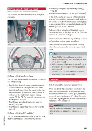
Page 9 of 272
<( a:, ... N .... N ... 0
s: a:,
7
Page 10 of 272
Cockpit overview
Cockpit overview
Controls at a glance
Fig. 1 Cockpit : left section
F ig. 2 Cockpit: rig ht sect ion
8
Page 11 of 272

<( co .... N r--N .... 0 r--> co
CD
@
®
©
®
®
(J)
®
Power windows
Door handle
Aud i side assist ... ......... .. .
Central locking switch .. ... .. .. .
Power exterior mirror ad justment
L ig ht swit ch .... . .......... .. .
Vents
L ever fo r:
- Turn signals and high beams . . .
- Audi a ct ive lane assis t ..... .. .
® Steer ing whee l w ith horn and
- Drive r's airbag ...... ..... .. .
- On-board compute r controls .. .
- MMI, telephone, navigation and
vo ice recognit ion system cont rols
- tiptronic sh ift paddles (automatic
transm iss ion) . .. .... ... .. .. .
@ Ins trumen t cluste r ....... .. .. .
© W indshield washer system lever .
@ Steering column with:
- Ignit ion emergency operation ( in
vehicles with convenience key) .
- Ignit io n lock (in vehicles wi th me - 34
103 3 1
47
43
61
4S
1 0 0
147
24
81 1 0
49
72
chanical key) . . . . . . . . . . . . . . . . 68
@ Adjustable steer ing column
(B) D epending on equipment: 67
- Cruise control leve r . . . . . . . . . . 88
- adaptive cruise contro l . . . . . . . 90
@ Driver's knee a irbag . . . . . . . . . . . 1S9
@ Ins trumen t illum ination . . . . . . . . 47
@ Hood release . . . . . . . . . . . . . . . . . 190
@ Central power w indow sw itch . . . . 34
@ MMI d isp lay (nav igat ion, radio, TV/
video)
@ Glove compartment (lockable) . . . S7
@ Fron t passenger's ai rbag . . . . . . . 147
@ Treble spea ke rs
@ Front passenger's k nee a irbag . . . 159
@ Depending on equipmen t, b utt ons
for:
- Audi dr ive select . . . . . . . . . . . . . 106
- Par king a id p lus (or with rearview
camera) .. ............... .. .
- Emerg ency flashers .. ... .. .. . 110
44
Coc
kpit o ve rv iew
- Elect ronic Stabilization Control
(ESC) ... .. .. .. .... . ..... .. .
- MMI Display
- Ai rbag Off i ndicator ......... .
@ Automatic climate contro l system
@ Socket ..... .. .. ... ......... .
@ S tronic selector lever .. ..... .. .
@ Cup holder .. .. .............. .
@) MM I On/Off button
@ MMI contro l pane l
@ Power top operation . ... ... .. . .
@ Par kin g b rake . .............. .
@) I START ENGINE STOP ! ........ .
(D Tips
- Some the eq uipment listed here is on ly in
sta lled in certai n models or is available as
an opt ion. 116
155
62
56
76
57
36
73
70
- Operation of the Multi Media Inte rface
(MMI) is described in a separate operating
instructions manual. You can also find info r-
mation on A udi connect t here.
9
Page 12 of 272

Instrumen ts and ind icator ligh ts
Instruments and indicator Lights
Instruments
Instrument cluster overview
The instrument cluster is the central information center for the driver.
Fig. 3 Instrument cluster overv iew
(D Tachometer with indicator lights
- with
OFF status indicator .... .
- with
RE ADY status indicator .. .
@ Engine coolant temperature gauge
@ Turn signal indicator lights
© Disp lay
- Indicator lights or ...... ... .. . 10
68, 70
68, 70
12
12
- Drive r informat ion system . . . . . 23
- Date and time . . . . . . . . . . . . . . . 10
- Mileage . . . . . . . . . . . . . . . . . . . . 11
- Service interval display . . . . . . . 202
® Speedometer w ith ind icator lights
@ Fue l level ...... ........... .. .
11
0 Display for : centra l indicator light
or system displays ............ . 12
@ Trip odometer reset button 10.01 11
@ Tips
The needles in the instrument cluster illumi
nate when the ignition is switched on . The di
als a lso illuminate when the lights are switch
ed on. The instrument illum ination d ims au
tomatically as the amount of light outside de
creases. T his he lps to remind the dr iver to
10
turn the headlights on as it becomes darker
outside.
Setting the time/date
Fig . 4 Instrument cluster: time and date
The date, time of day, time and date format can
be set in the MMI. For more information, refer to
your MMI Operating Manual.
Tachometer
The tachometer displays the engine speed in rev
olutions per minute (RPM).
The beginning of the red zone in the tachometer
indicates the maximum permitted engine speed .,,_
Page 13 of 272

<( co
for all gears once the engine has been broken in
and when it is warm. You should select the D/S
se lector lever position or take your foot off the
accelerator pedal before reaching th is area .
CD Note
The needle in the tachometer (D c::> page 10,
fig.
3 may only be in the red area of the gauge
for a short time or there is a risk of damaging
the engine.
@ For the sake of the env ironment
Upshifting early helps you to save fuel and re
duce operating noise.
Odometer
Fig . S In strum ent cl uster : odo meter
Tr ip o dom eter and odom eter
-~ 0
> a, ID
The trip odometer @ shows the distance driven
since it was last reset. It can be used to measure
short distances .
The trip odometer can be reset to zero by press ing the reset button
10.01 c::> page 10, fig. 3.
The odometer @shows the total distance that
the vehicle has been dr iven.
M alfun cti on indic ator
If there is a malfunction in the instrument clus
ter,
DEF w ill appear in the tr ip odometer display .
H ave the malfunction corrected as soon as possi
b le.
@ Tips
;::: The units of measurement can be set in the
" ~ MMI.
0
" > 00
Inst rum ents a nd ind icat or ligh ts
Outside temperature display
The instrument clus ter display shows the outside
temperature. At temperatures below 41 °F
( + 5 °C), a snowflake symbol appears in front of
the temperature display.
If your vehicle is stationary or if you are driv ing at
very low speeds, the temperature d isplayed may
be slight ly higher than the actual temperature
outside due to the heat radiating from the en
gine.
A WARNING
-
Do not assume the roads are free of ice based
on the outside temperature display. Be aware
that there may be ice on roads even when the
outside temperature is around 41 °F
(+5 °()
and that ice can increase the risk of acc idents.
@ Tips
The units of measurement can be set in the
MMI.
Fuel level
The display @c::>page10 , fig. 3 only works when
the ignit ion is switched on . When the display has
reached the rese rve ma rk, the bottom LED will
tu rn red and the
ti ind icator light t urns on
c::>page 20. The bottom LED blinks red when
the fuel level is very low .
The on-board computer shows the range based on the fuel level c::>
page 23, On-board comput
er display.
For the tank capacity in your veh icle, refer to the
Technica l Data
c::> page 251.
CD Note
Never drive until the tank is completely emp
ty . The ir regular supply of fue l that resu lts
from that can cause engine misfires. Uncom
busted fuel w il l then enter the exha ust sys
tem. This can cause overheat ing and damage
to the catalytic converter.
1 1
Page 14 of 272

Instruments and indicator lights
Coolant temperature indicator
The coolant temperature indicator@¢ page 10,
fig . 3
only works when the ignition is switched
on. To prevent engine damage, please observe
the following notes about the temperature rang
es.
Cold range
If only the LEDs at the bottom of the gauge turn
on, the engine has not reached operating tem
perature yet. Avoid high engine speeds, full ac
celerating and heavy engine loads.
Normal range
The engine has reached its operating tempera
ture once the LEDs up to the center of the gauge
turn on under normal driving conditions. The
LEDs higher up may turn on if the engine is under
heavy load or the outside temperature is high.
This is no cause for conc ern as long as the. in
dicator light in the instrument cluster does not
turn on.
Hot range
If the LEDs in the upper area of the display and
the . indicator light in the instrument cluster
display turn on, the coolant temperature is too
high
¢ page 16.
A WARNING
-Never open the hood if you can see or hear
steam or coolant escaping from the engine
compartment. This increases the risk of
burns. Wait until you no longer see or hear
steam or coolant escap ing .
- The engine compartment in any vehicle can
be a dangerous area. Stop the engine and
allow it to cool before working in the engine
compartment. A lways follow the informa
tion found in ¢
page 188, Working in the
engine comportment.
(D Note
- Auxiliary headlights and other accessories in
front of the cooling-air intake impair the
cooling effect of the coolant. This increases
the risk of the engine overheating during
12
high outside temperatures and heavy en
gine load.
- Th e front spoiler also helps to distribute
cooling air correctly while driving. If the
spoiler is damaged, the cooling effect will
be impaired and the risk of the engine over
heating will increase. See an authorized
Audi dealer or authorized Audi Service Fa cility for assistance .
Indicator lights
Description
The indicator lights in the instrument cluster
blink or turn on. They indicate functions or mal
functions.
Messages may appear with some indicator lights.
A warning signal will sound at the same time. If
there is more than one malfunction, the indicator lights will turn on one after the other for a short
time . The indicator lights and messages in the in
strument cluster display can be covered by other
displays .
The messages can be displayed again in the driv
er information system*. With the multifunction
steering wheel, select the tab for indicator lights
and messages
c:> page 24 .
Some indicator lights in the display can display in
several colors.
& Central indicator light
If the . or D indicator light turns on, check
the instrument cluster display for more informa
tion.
App lies to: vehicles wi th mo nochrome disp lay
If a message appears together with a central in
dicator light. or
D. the central indicator light
will indicate the priority of the warning. If a
white indicator light also appears , the central in
dicator light will have its own color . For example,
i'"
@I ::ippears together with., read the descrip
tion for •.
Page 15 of 272

<( co .... N r--N .... 0 r--> co
Overview
Some ind icator lights tu rn o n briefly as a fu nction
check whe n you swi tch the ig nition on. These sys
t ems are mar ke d wit h a ./ in the following tables.
If one of these indica to r li ghts does no t turn on,
there is a ma lfunction in t hat system.
Red indicator lights
r-------------
C en t r al indi cato r ligh t
¢ page 12,
Audi pre sense *
¢page98
USA models:
Brak e sys tem ./
¢page 15
Canada models:
Brak e sys tem ./
¢page 15
USA models:
Elect romecha nica l park ing brake
¢page 15
Canada models:
Electromechan ica l pa rk ing bra ke
¢page 15
Cooling system
¢page 16
Eng ine oil pressure
¢pag e 16
Alternator
c:::> page 17
Front safety belt
c:::>page 17
Steering ./
c:::> page 119
Steer ing lock
¢page 17
Eng ine st art system
¢ page 18
Eng ine stop wh ile dr iving
¢page 18
Transmiss ion malfunc tio n
¢ pa ge8 2
Adapt ive cr uise control* ./
c:::>pag e 92
Instruments and ind icator lights
USA models: spe ed wa rning sys
t em
¢ page 88
Canada models: speed wa rni ng
system
c:::> page 88
Yellow indicator lights
-------------
Cen tral indic ator light
¢ page 12,
Brake booster
¢ page 15
Electron ic Stab ilization Contro l
( ES C) ./
i=>pag e 18
Elec tronic Sta biliz ation Contro l
(ESC) ./
¢page 18
Electronic Stab ilization Contro l
(ESC)
USA models:
An ti-lock b raking sys tem (A BS) ./
c>page 18
Canada models:
Anti-lock b raking system (ABS) ./
¢page 18
USA models : safety systems ./
¢pa ge 17
Canada models : safety systems ./
c:::>page 17
Electromechanical parking brake
c:::> page 15
Hill
ho ld assist*
¢ page 19
Tire pressure mo nitor ing indicator
./
T ire p ressure mo nitor ing indicator
¢ page222 ..,.
13
Page 16 of 272

Instruments and indicator lights
y>))
14
Damper cont rol*
¢ page21
Engine control (gaso line engine)./
¢ page 19
Emiss ions control system./
¢ page 19
Eng ine speed limitat ion
¢ page 19
Engine oil level (min.)
¢page20
Engine oil senso r
¢page 20
Engine temperature
¢page 16
Battery charge
¢page 17
Tank system
¢ page20
Washer fluid level
¢page20
Windshield wipe rs
¢ page20
Steering .// steering lock
¢page 119
Steering lock
¢ page 17
Engine start system
¢page 18
Convenience key
¢page 72
Conve nience key
¢page 72
Batte ry in remote cont rol key
¢ page28
Bulb failure ind icator
¢ page20
Headlight ra nge control system*
¢ page 21
Adaptive light*
¢page 21
Light/rain sensor*
¢ page 21
Active lane assist*
¢page 101
Transmission
¢ page 82
Other indicator light s
/:
~-------------
Turn signals
¢page 21
USA model s: c ruise con tro l sys
tem*
¢ page 88
Canada model s: cruise contro l sys
tem*
¢ page 88
Adaptive cruise contro l*
¢ page 92
Adaptive c ruise contro l*
¢ page 92
Adaptive cruise contro l*
¢ page 92
Active lane assist*
¢ page 101
High beams
¢ page45
Convenie nce key
¢ page 72
Electromechanical parking brake
¢page 15
Adaptive cruise contro l*
¢ page 92
Active lane assist*
¢page 101
Audi side assist*
¢page 105
Transmission
¢page 82
USA model s:
E lec tromechanical parking brake
¢ page 15
Canada model s:
El ectromechanical pa rking brake
¢ page 15