Page 41 of 108

INSTRUMENT AND CONTROL FUNCTIONS
3-26
3
EAU15306
Sidestan dThe sidestand is located on the left
side of the frame. Raise the sidestand
or lower it with your foot while holding
the vehicle upright.TIPThe built-in sidestand switch is part of
the ignition circuit cut-off system,
which cuts the ignition in certain situa-
tions. (See the following section for an
explanation of the ignition circuit cut-
off system.)
WARNING
EWA10242
The vehicle must not b e ridden with
the si destan d d own, or if the si de-
stan d cannot b e properly move d up
(or does not stay up), otherwise the
si destan d coul d contact the g round
an d d istract the operator, resultin g
in a possi ble loss of control.
Yamaha’s i gnition circuit cut-off
system has been desi gne d to assist
the operator in fulfilling the respon-
si bility of raisin g the si destan d b e-
fore startin g off. Therefore, check this system re
gularly an d have a
Yamaha dealer repair it if it does not
function properly.
EAU57950
I g nition circuit cut-off systemThe ignition circuit cut-off system
(comprising the sidestand switch,
clutch switch and neutral switch) has
the following functions.
It prevents starting when the
transmission is in gear and the
sidestand is up, but the clutch le-
ver is not pulled.
It prevents starting when the
transmission is in gear and the
clutch lever is pulled, but the side-
stand is still down.
It cuts the running engine when
the transmission is in gear and the
sidestand is moved down.
Periodically check the operation of the
ignition circuit cut-off system accord-
ing to the following procedure.
U1RCE1E0.book Page 26 Wednesday, May 28, 2014 1:10 PM
Page 42 of 108

INSTRUMENT AND CONTROL FUNCTIONS
3-27
3
With the engine turned off:
1. Move the sidestand down.
2. Make sure that the start/engine stop switch is set to “ ”.
3. Turn the key on.
4. Shift the transmission into the neutral position.
5. Push the “ ” side of the start/engine stop switch.
Does the engine start?
With the engine still running:
6. Move the sidestand up.
7. Keep the clutch lever pulled.
8. Shift the transmission into gear.
9. Move the sidestand down.
Does the engine stall?
After the engine has stalled:
10. Move the sidestand up.
11. Keep the clutch lever pulled.
12. Push the “ ” side of the start/engine stop switch.
Does the engine start?
The system is OK. The motorcycle can be ridden.
YES NO YES NO YES NO
The neutral switch may not be working correctly.
The motorcycle should not be ridden until
checked by a Yamaha dealer.
The clutch switch may not be working correctly.
The motorcycle should not be ridden until
checked by a Yamaha dealer.The sidestand switch may not be working correctly.
The motorcycle should not be ridden until
checked by a Yamaha dealer.If a malfunction is noted, have a Yamaha
dealer check the system before riding.
WA R N I N G
U1RCE1E0.book Page 27 Wednesday, May 28, 2014 1:10 PM
Page 43 of 108
INSTRUMENT AND CONTROL FUNCTIONS
3-28
3
EAU58262
Auxiliary DC connector
WARNING
EWA12532
To prevent electrical shock or short-
circuiting, make sure that the cap is
installe d when the auxiliary DC con-
nector is not bein g use d.NOTICE
ECA20090
The accessory connected to the
auxiliary DC connector shoul d not
b e used with the en gine turne d off,
an d the loa d must never exceed 24
W (2 A), otherwise the fuse may blow
or the battery may dischar ge.
A 12 V accessory connected to the
auxiliary DC connector behind the right
side panel can be used when the key is
in the “ON” position. (See page 6-30.)
1. Auxiliary DC connector
2. Auxiliary DC connector cap21
U1RCE1E0.book Page 28 Wednesday, May 28, 2014 1:10 PM
Page 44 of 108

FOR YOUR SAFETY – PRE-OPERATION CHECKS
4-1
4
EAU15598
Inspect your vehicle each time you use it to make sure the vehicle is in safe operating condition. Always follow the inspection
and maintenance procedures and schedules described in the Owner’s Manual.
WARNING
EWA11152
Failure to inspect or maintain the vehicle properly increases the possibility of an acci dent or equipment damag e.
Do not operate the vehicle if you fin d any pro blem. If a pro blem cannot b e corrected b y the proce dures provi ded in
this manual, have the vehicle inspecte d b y a Yamaha dealer.Before using this vehicle, check the following points:
ITEM CHECKS PAGE
Fuel • Check fuel level in fuel tank.
• Refuel if necessary.
• Check fuel line for leakage.
• Check fuel tank breather hose and overflow hose for obstructions, cracks or
damage, and check hose connections. 3-19, 3-20
En gine oil • Check oil level in engine.
• If necessary, add recommended oil to specified level.
• Check vehicle for oil leakage. 6-9
Coolant • Check coolant level in reservoir.
• If necessary, add recommended coolant to specified level.
• Check cooling system for leakage. 6-11
Front brake • Check operation.
• If soft or spongy, have Yamaha dealer bleed hydraulic system.
• Check brake pads for wear.
• Replace if necessary.
• Check fluid level in reservoir.
• If necessary, add specified brake fluid to specified level.
• Check hydraulic system for leakage. 6-20, 6-21
U1RCE1E0.book Page 1 Wednesday, May 28, 2014 1:10 PM
Page 45 of 108

FOR YOUR SAFETY – PRE-OPERATION CHECKS
4-2
4
Rear brake • Check operation.
• If soft or spongy, have Yamaha dealer bleed hydraulic system.
• Check brake pads for wear.
• Replace if necessary.
• Check fluid level in reservoir.
• If necessary, add specified brake fluid to specified level.
• Check hydraulic system for leakage. 6-20, 6-21
Clutch • Check operation.
• Lubricate cable if necessary.
• Check lever free play.
• Adjust if necessary.
6-18
Throttle grip • Make sure that operation is smooth.
• Check throttle grip free play.
• If necessary, have Yamaha dealer adjust throttle grip free play and lubricate ca-
ble and grip housing. 6-15, 6-25
Control ca bles • Make sure that operation is smooth.
• Lubricate if necessary. 6-25
Drive chain • Check chain slack.
• Adjust if necessary.
• Check chain condition.
• Lubricate if necessary.
6-22, 6-24
Wheels an d tires • Check for damage.
• Check tire condition and tread depth.
• Check air pressure.
• Correct if necessary.
6-15, 6-18
Brake an d shift pe dals • Make sure that operation is smooth.
• Lubricate pedal pivoting points if necessary. 6-25
Brake an d clutch levers • Make sure that operation is smooth.
• Lubricate lever pivoting points if necessary.
6-26
Si destan d • Make sure that operation is smooth.
• Lubricate pivot if necessary.
6-27
ITEM CHECKS PAGE
U1RCE1E0.book Page 2 Wednesday, May 28, 2014 1:10 PM
Page 46 of 108
FOR YOUR SAFETY – PRE-OPERATION CHECKS
4-3
4
Chassis fasteners• Make sure that all nuts, bolts and screws are properly tightened.
• Tighten if necessary. —
Instruments, li ghts, si gnals
an d switches • Check operation.
• Correct if necessary.
—
Si destan d switch • Check operation of ignition circuit cut-off system.
• If system is not working correctly, have Yamaha dealer check vehicle. 3-26
ITEM CHECKS PAGE
U1RCE1E0.book Page 3 Wednesday, May 28, 2014 1:10 PM
Page 47 of 108

OPERATION AND IMPORTANT RIDING POINTS
5-1
5
EAU15952
Read the Owner’s Manual carefully to
become familiar with all controls. If
there is a control or function you do not
understand, ask your Yamaha dealer.
WARNING
EWA10272
Failure to familiarize yourself with
the controls can lead to loss of con-
trol, which coul d cause an acci dent
or injury.
EAU48711
TIPThis model is equipped with: a lean angle sensor to stop the en-
gine in case of a turnover. In this
case, the multi-function display in-
dicates error code 30, but this is
not a malfunction. Turn the key to
“OFF” and then to “ON” to clear
the error code. Failing to do so will
prevent the engine from starting
even though the engine will crank
when pushing the start switch.
an engine auto-stop system. The
engine stops automatically if left
idling for 20 minutes. If the engine
stops, simply push the start
switch to restart the engine.
EAU58030
Startin g the en gineIn order for the ignition circuit cut-off
system to enable starting, one of the
following conditions must be met:
The transmission is in the neutral
position.
The transmission is in gear with
the clutch lever pulled and the
sidestand up.
See page 3-26 for more informa-
tion.
1. Turn the key to “ON” and make sure that the start/engine stop
switch is set to “ ”.
The following warning lights and
indicator light should come on for
a few seconds, then go off. Oil level warning light
Coolant temperature warning
light
Engine trouble warning light
Immobilizer system indicator
lightNOTICE
ECA17671
If the a bove warnin g li ghts or ind ica-
tor li ght do not come on initially
when the key is turned to “ON”, or if
U1RCE1E0.book Page 1 Wednesday, May 28, 2014 1:10 PM
Page 48 of 108

OPERATION AND IMPORTANT RIDING POINTS
5-2
5a warnin
g or in dicator li ght remains
on, see pa ge 3-3 for the correspon d-
in g warnin g an d in dicator li ght cir-
cuit check.
For ABS models:The ABS warning light should
come on when the key is turned to
“ON”, and then go off after travel-
ing at a speed of 10 km/h (6 mi/h)
or higher.
NOTICE
ECA17682
If the ABS warnin g lig ht does not
come on an d then g o off as ex-
plaine d a bove, see pa ge 3-3 for the
warnin g lig ht circuit check.2. Shift the transmission into the
neutral position. The neutral indi-
cator light should come on. If not,
ask a Yamaha dealer to check the
electrical circuit.
3. Start the engine by pushing the “ ” side of the start/engine
stop switch.
If the engine fails to start, release
the start/engine stop switch, wait
a few seconds, and then try again.
Each starting attempt should be as short as possible to preserve
the battery. Do not crank the en-
gine more than 10 seconds on any
one attempt.
NOTICE
ECA11043
For maximum en
gine life, never ac-
celerate har d when the en gine is
col d!
EAU16673
Shiftin gShifting gears lets you control the
amount of engine power available for
starting off, accelerating, climbing hills,
etc.
The gear positions are shown in the il-
lustration.TIPTo shift the transmission into the neu-
tral position, press the shift pedal down
repeatedly until it reaches the end of its
travel, and then slightly raise it.1. Shift pedal
2. Neutral position
1
N
2 3
4
5
6
1
2
U1RCE1E0.book Page 2 Wednesday, May 28, 2014 1:10 PM
 1
1 2
2 3
3 4
4 5
5 6
6 7
7 8
8 9
9 10
10 11
11 12
12 13
13 14
14 15
15 16
16 17
17 18
18 19
19 20
20 21
21 22
22 23
23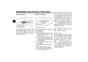 24
24 25
25 26
26 27
27 28
28 29
29 30
30 31
31 32
32 33
33 34
34 35
35 36
36 37
37 38
38 39
39 40
40 41
41 42
42 43
43 44
44 45
45 46
46 47
47 48
48 49
49 50
50 51
51 52
52 53
53 54
54 55
55 56
56 57
57 58
58 59
59 60
60 61
61 62
62 63
63 64
64 65
65 66
66 67
67 68
68 69
69 70
70 71
71 72
72 73
73 74
74 75
75 76
76 77
77 78
78 79
79 80
80 81
81 82
82 83
83 84
84 85
85 86
86 87
87 88
88 89
89 90
90 91
91 92
92 93
93 94
94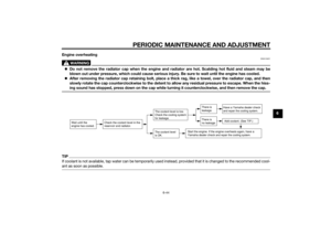 95
95 96
96 97
97 98
98 99
99 100
100 101
101 102
102 103
103 104
104 105
105 106
106 107
107
