Page 25 of 108

INSTRUMENT AND CONTROL FUNCTIONS
3-10
3
km/L, L/100 km or MPG
→ AVE_ _._
km/L, AVE_ _._ L/100 km or AVE_ _._
MPG → °C → Air_ _ °C → ODO →
TRIP 1 → TRIP 2
TIPPush the “RESET” button to switch the
display in the reverse order.If the fuel level warning indicator “ ”
and left segment of the fuel meter start
flashing, the display automatically
changes to the fuel reserve tripmeter
mode “F-TRIP” and starts counting the
distance traveled from that point. In
that case, push the “SELECT” button
to switch the display between the vari-
ous tripmeter, odometer, instanta-
neous fuel consumption and average
fuel consumption modes in the follow-
ing order:
F-TRIP → km/L or L/100 km → AVE_
_._ km/L or AVE_ _._ L/100 km → °C →
Air_ _ °C → ODO → TRIP 1 → TRIP 2
→ F-TRIP For the UK only:
F-TRIP
→ km/L, L/100 km or MPG →
AVE_ _._ km/L, AVE_ _._ L/100 km or
AVE_ _._ MPG → °C → Air_ _ °C →
ODO → TRIP 1 → TRIP 2 → F-TRIP
To reset a tripmeter, select it by push-
ing the “SELECT” button, and then
push the “RESET” button for at least
one second.
If you do not reset the fuel reserve trip-
meter manually, it resets itself auto-
matically and the display returns to the
prior mode after refueling and traveling
5 km (3 mi).
Instantaneous fuel consumption
d isplay The instantaneous fuel consumption
display can be set to either “km/L”,
“L/100 km” or “MPG” (for the UK only).
“km/L”: The distance that can be
traveled on 1.0 L of fuel under the
current riding conditions is shown.
“L/100 km”: The amount of fuel
necessary to travel 100 km under
the current riding conditions is
shown.
“MPG” (for the UK only): The dis-
tance that can be traveled on
1.0 Imp.gal of fuel under the cur-
rent riding conditions is shown.
To switch between the instantaneous
fuel consumption displays, push the
“SELECT” button for one second when
one of the displays is shown.
TIPIf traveling at speeds under 20 km/h
(12 mi/h), “_ _._” is displayed.
1. Instantaneous fuel consumption display
1
U1RCE1E0.book Page 10 Wednesday, May 28, 2014 1:10 PM
Page 26 of 108

INSTRUMENT AND CONTROL FUNCTIONS
3-11
3Averag
e fuel consumption display
The average fuel consumption display
can be set to either “AVE_ _._ km/L”,
“AVE_ _._ L/100 km” or “AVE_ _._
MPG” (for the UK only).
This display shows the average fuel
consumption since it was last reset. “AVE_ _._ km/L”: The average dis-
tance that can be traveled on 1.0 L
of fuel is shown.
“AVE_ _._ L/100 km”: The average
amount of fuel necessary to travel
100 km is shown.
“AVE_ _._ MPG” (for the UK only):
The average distance that can be
traveled on 1.0 Imp.gal of fuel is
shown. To switch between the average fuel
consumption displays, push the “SE-
LECT” button for one second when
one of the displays is shown.
To reset the average fuel consumption
display, select it by pushing the “SE-
LECT” button, and then push the “RE-
SET” button for at least one second.
TIPAfter resetting an average fuel con-
sumption display, “_ _._” is shown for
that display until the vehicle has trav-
eled 1 km (0.6 mi).Coolant temperature
display This display shows the coolant tem-
perature from 40 °C to 116 °C in 1 °C
increments.
If the message “HI” flashes, stop the
vehicle, then stop the engine, and let
the engine cool. (See page 6-44.)
TIP
When the coolant temperature is
below 40 °C, “LO” will be dis-
played.
The coolant temperature varies
with changes in the weather and
engine load.Air intake temperature display
1. Average fuel consumption display
1
1. Coolant temperature display
1
1. Air intake temperature display
1
U1RCE1E0.book Page 11 Wednesday, May 28, 2014 1:10 PM
Page 27 of 108

INSTRUMENT AND CONTROL FUNCTIONS
3-12
3
The air intake temperature display indi-
cates the temperature of the air drawn
into the air filter case.
This display shows the air intake tem-
perature from –9 °C to 99 °C in 1 °C in-
crements.
TIP
–9 °C will be displayed even if the
air intake temperature falls below
–9 °C.
The air intake temperature may
vary from the ambient tempera-
ture.Bri ghtness control mo de This function allows you to adjust the
brightness of the multi-function meter
unit panel to suit the outside lighting
conditions.
To adjust the brightness
1. Turn the key to “OFF”.
2. While pushing the “SELECT” but-
ton, turn the key to “ON” and con-
tinue pushing the button until the
display switches to the brightness
control mode.
3. Push the “RESET” button to set the brightness level.
4. Push the “SELECT” button to re- turn to the original display. Self-d
iagnosis device
This model is equipped with a self-di-
agnosis device for various electrical
circuits.
If a problem is detected in any of those
circuits, the engine trouble warning
light will come on and the display will
indicate an error code.
If the display indicates any error codes,
note the code number, and then have
a Yamaha dealer check the vehicle.
The self-diagnosis device also detects
problems in the immobilizer system
circuits.
1. Brightness level display
1
1. Error code display
2. Engine trouble warning light “ ”
3. Immobilizer system indicator light “ ”
1
2
3
U1RCE1E0.book Page 12 Wednesday, May 28, 2014 1:10 PM
Page 28 of 108

INSTRUMENT AND CONTROL FUNCTIONS
3-13
3If a problem is detected in the immobi-
lizer system circuits, the immobilizer
system indicator light will flash and the
display will indicate an error code.
TIPIf the display indicates error code 52,
this could be caused by transponder
interference. If this error code appears,
try the following.1. Use the code re-registering key to
start the engine.TIPMake sure there are no other immobi-
lizer keys close to the main switch, and
do not keep more than one immobilizer
key on the same key ring! Immobilizer
system keys may cause signal interfer-
ence, which may prevent the engine
from starting.2. If the engine starts, turn it off andtry starting the engine with the
standard keys.
3. If one or both of the standard keys do not start the engine, take the
vehicle, the code re-registering key and both standard keys to a
Yamaha dealer and have the stan-
dard keys re-registered.
NOTICE
ECA11591
If the
display in dicates an error co-
d e, the vehicle shoul d b e checked as
soon as possi ble in or der to avoi d
en gine damag e.
EAU47634
D-mode ( drive mo de)D-mode is an electronically controlled
engine performance system with three
mode selections (“STD”, “A”, and “B”).
Push the drive mode switch “MODE”
to switch between modes. (See page
3-15 for an explanation of the drive
mode switch.)TIPBefore using D-mode, make sure you
understand its operation along with the
operation of the drive mode switch.Mo de “STD”
Mode “STD” is suitable for various rid-
ing conditions.1. Drive mode switch “MODE”
1
U1RCE1E0.book Page 13 Wednesday, May 28, 2014 1:10 PM
Page 29 of 108

INSTRUMENT AND CONTROL FUNCTIONS
3-14
3
This mode allows the rider to enjoy
smooth and sporty drivability from the
low-speed range to the high-speed
range.
Mo
de “A”
Mode “A” offers a sportier engine re-
sponse in the low- to mid-speed range
compared to mode “STD”.
Mo de “B”
Mode “B” offers response that is
somewhat less sharp compared to
mode “STD” for riding situations that
require especially sensitive throttle op-
eration.
EAU1234H
Han dle bar switchesLeft Ri
ght
EAU12351
Pass switch “ ”
Press this switch to flash the headlight.
EAU12401
Dimmer switch “ / ”
Set this switch to “ ” for the high
beam and to “ ” for the low beam.
EAU12461
Turn si gnal switch “ / ”
To signal a right-hand turn, push this
switch to “ ”. To signal a left-hand
turn, push this switch to “ ”. When
released, the switch returns to the cen-
1. Pass switch “ ”
2. Dimmer switch “ / ”
3. Turn signal switch “ / ”
4. Horn switch “ ”
2341
1. Start/Engine stop switch “ / / ”
2. Drive mode switch “MODE”
3. Hazard switch “ ”
123
U1RCE1E0.book Page 14 Wednesday, May 28, 2014 1:10 PM
Page 30 of 108

INSTRUMENT AND CONTROL FUNCTIONS
3-15
3ter position. To cancel the turn signal
lights, push the switch in after it has re-
turned to the center position.
EAU12501
Horn switch “ ”
Press this switch to sound the horn.
EAU54211
Start/En
gine stop switch “ / / ”
To crank the engine with the starter,
set this switch to “ ”, and then push
the “ ” side of the switch. See page
5-1 for starting instructions prior to
starting the engine.
Set this switch to “ ” to stop the en-
gine in case of an emergency, such as
when the vehicle overturns or when the
throttle cable is stuck.
EAU41701
The engine trouble warning light will
come on when the key is turned to
“ON” and the start switch is pushed,
but this does not indicate a malfunc-
tion.
EAU12735
Hazar d switch “ ”
With the key in the “ON” or “ ” posi-
tion, use this switch to turn on the haz-
ard lights (simultaneous flashing of all
turn signal lights).
The hazard lights are used in case of an
emergency or to warn other drivers
when your vehicle is stopped where it
might be a traffic hazard.NOTICE
ECA10062
Do not use the hazard lights for an
exten ded len gth of time with the en-
g ine not runnin g, otherwise the bat-
tery may dischar ge.
EAU47496
Drive mo de switch “MODE”
WARNING
EWA15341
Do not chan ge the D-mo de while the
vehicle is movin g.Using this switch changes the drive
mode to “STD”, “A”, or “B” in the fol-
lowing order:
STD → A → B → STD The throttle grip must be completely
closed in order to change the drive mo-
de. (See page 3-13 for an explanation
of each drive mode.)
TIP
The mode is set to “STD” by de-
fault. The mode resets to “STD”
when the key is turned to “OFF”.
The selected mode is shown on
the drive mode display. (See page
3-9.)
U1RCE1E0.book Page 15 Wednesday, May 28, 2014 1:10 PM
Page 31 of 108

INSTRUMENT AND CONTROL FUNCTIONS
3-16
3
EAU12821
Clutch leverThe clutch lever is located at the left
handlebar grip. To disengage the
clutch, pull the lever toward the han-
dlebar grip. To engage the clutch, re-
lease the lever. The lever should be
pulled rapidly and released slowly for
smooth clutch operation.
The clutch lever is equipped with a
clutch switch, which is part of the igni-
tion circuit cut-off system. (See page
3-26.)
EAU12872
Shift pedalThe shift pedal is located on the left
side of the motorcycle and is used in
combination with the clutch lever when
shifting the gears of the 6-speed con-
stant-mesh transmission equipped on
this motorcycle.
EAU26825
Brake leverThe brake lever is located on the right
side of the handlebar. To apply the
front brake, pull the lever toward the
throttle grip.
The brake lever is equipped with a
brake lever position adjusting dial. To
adjust the distance between the brake
lever and the throttle grip, turn the ad-
justing dial while holding the lever
pushed away from the throttle grip.
Make sure that the appropriate setting
on the adjusting dial is aligned with
the “ ” mark on the brake lever.
1. Clutch lever
1
1. Shift pedal
1
1. Brake lever
2. Distance between brake lever and throttle
grip
3. Brake lever position adjusting dial
4. “ ” mark
543
21
1
2
43
U1RCE1E0.book Page 16 Wednesday, May 28, 2014 1:10 PM
Page 32 of 108

INSTRUMENT AND CONTROL FUNCTIONS
3-17
3
EAU12944
Brake pedalThe brake pedal is located on the right
side of the motorcycle. To apply the
rear brake, press down on the brake
pedal.
EAU51802
ABS (for ABS mo dels)The Yamaha ABS (Anti-lock Brake
System) features a dual electronic con-
trol system, which acts on the front and
rear brakes independently.
Operate the brakes with ABS as you
would conventional brakes. If the ABS
is activated, a pulsating sensation may
be felt at the brake lever or brake ped-
al. In this situation, continue to apply
the brakes and let the ABS work; do
not “pump” the brakes as this will re-
duce braking effectiveness.
WARNING
EWA16051
Always keep a sufficient d istance
from the vehicle ahea d to match the
ri din g spee d even with ABS.
The ABS performs best with
lon g b rakin g d istances.
On certain surfaces, such as
rou gh or g ravel roa ds, the b rak-
in g d istance may b e longer with
the ABS than without.The ABS is monitored by an ECU,
which will revert the system to conven-
tional braking if a malfunction occurs.
TIP The ABS performs a self-diagno-
sis test each time the vehicle first
starts off after the key is turned to
“ON” and the vehicle has traveled
at a speed of 10 km/h (6 mi/h) or
higher. During this test, a “click-
ing” noise can be heard from un-
der the seat, and if the brake lever
or brake pedal is even slightly ap-
plied, a vibration can be felt at the
lever and pedal, but these do not
indicate a malfunction.
This ABS has a test mode which
allows the owner to experience
the pulsation at the brake lever or
brake pedal when the ABS is op-
erating. However, special tools are
required, so please consult your
Yamaha dealer.NOTICE
ECA16121
Keep any type of mag nets (includin g
ma gnetic pick-up tools, mag netic
screwd rivers, etc.) away from the
front an d rear wheel hu bs, otherwise
the ma gnetic rotors equippe d in the
1. Brake pedal
1
U1RCE1E0.book Page 17 Wednesday, May 28, 2014 1:10 PM
 1
1 2
2 3
3 4
4 5
5 6
6 7
7 8
8 9
9 10
10 11
11 12
12 13
13 14
14 15
15 16
16 17
17 18
18 19
19 20
20 21
21 22
22 23
23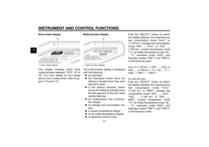 24
24 25
25 26
26 27
27 28
28 29
29 30
30 31
31 32
32 33
33 34
34 35
35 36
36 37
37 38
38 39
39 40
40 41
41 42
42 43
43 44
44 45
45 46
46 47
47 48
48 49
49 50
50 51
51 52
52 53
53 54
54 55
55 56
56 57
57 58
58 59
59 60
60 61
61 62
62 63
63 64
64 65
65 66
66 67
67 68
68 69
69 70
70 71
71 72
72 73
73 74
74 75
75 76
76 77
77 78
78 79
79 80
80 81
81 82
82 83
83 84
84 85
85 86
86 87
87 88
88 89
89 90
90 91
91 92
92 93
93 94
94 95
95 96
96 97
97 98
98 99
99 100
100 101
101 102
102 103
103 104
104 105
105 106
106 107
107