Page 33 of 108
INSTRUMENT AND CONTROL FUNCTIONS
3-18
3
wheel hu
bs may be damag ed , re-
sultin g in improper performance of
the ABS system.
EAU13075
Fuel tank capTo open the fuel tank cap
Open the fuel tank cap lock cover, in-
sert the key into the lock, and then turn
it 1/4 turn clockwise. The lock will be
released and the fuel tank cap can be
opened.
To close the fuel tank cap 1. Push the fuel tank cap into posi- tion with the key inserted in the
lock.
2. Turn the key counterclockwise to the original position, remove it,
and then close the lock cover.
TIPThe fuel tank cap cannot be closed un-
less the key is in the lock. In addition,
the key cannot be removed if the cap is
not properly closed and locked.
WARNING
EWA11092
Make sure that the fuel tank cap is
properly close d after fillin g fuel.
Leakin g fuel is a fire hazar d.
1. Unlock.
2. Fuel tank cap lock cover
2
1
U1RCE1E0.book Page 18 Wednesday, May 28, 2014 1:10 PM
Page 34 of 108

INSTRUMENT AND CONTROL FUNCTIONS
3-19
3
EAU13222
FuelMake sure there is sufficient gasoline in
the tank.
WARNING
EWA10882
Gasoline and g asoline vapors are
extremely flammab le. To avoid fires
an d explosions an d to re duce the
risk of injury when refuelin g, follow
these instructions.1. Before refueling, turn off the en- gine and be sure that no one is sit-
ting on the vehicle. Never refuel
while smoking, or while in the vi-
cinity of sparks, open flames, or
other sources of ignition such as
the pilot lights of water heaters
and clothes dryers.
2. Do not overfill the fuel tank. When refueling, be sure to insert the
pump nozzle into the fuel tank filler
hole. Stop filling when the fuel
reaches the bottom of the filler
tube. Because fuel expands when
it heats up, heat from the engine or
the sun can cause fuel to spill out
of the fuel tank. 3. Wipe up any spilled fuel immedi-
ately. NOTICE: Immediately
wipe off spille d fuel with a clean,
d ry, soft cloth, since fuel may
d eteriorate painted surfaces or
plastic parts.
[ECA10072]
4. Be sure to securely close the fuel tank cap.
WARNING
EWA15152
Gasoline is poisonous an d can cau-
se injury or death. Han dle gasoline
with care. Never siphon gasoline by
mouth. If you shoul d swallow some
g asoline or inhale a lot of g asoline
vapor, or g et some gasoline in your
eyes, see your d octor immediately. If g
asoline spills on your skin, wash
with soap an d water. If gasoline
spills on your clothin g, chan ge your
clothes.
EAU58110
NOTICE
ECA11401
Use only unlea ded g asoline. The use
of lea ded g asoline will cause severe
d amag e to internal en gine parts,
such as the valves an d piston rin gs,
as well as to the exhaust system.Your Yamaha engine has been de-
signed to use premium unleaded gas-
oline with a research octane number of
95 or higher. If knocking (or pinging)
occurs, use a gasoline of a different
1. Fuel tank filler tube
2. Maximum fuel level
1
2
Recommen ded fuel:
Premium unleaded gasoline (Gaso-
hol (E10) acceptable)
Fuel tank capacity:
14.0 L (3.70 US gal, 3.08 Imp.gal)
Fuel reserve amount: 2.8 L (0.74 US gal, 0.62 Imp.gal)
U1RCE1E0.book Page 19 Wednesday, May 28, 2014 1:10 PM
Page 35 of 108

INSTRUMENT AND CONTROL FUNCTIONS
3-20
3
brand. Use of unleaded fuel will extend
spark plug life and reduce mainte-
nance costs.
Gasohol
There are two types of gasohol: gaso-
hol containing ethanol and that con-
taining methanol. Gasohol containing
ethanol can be used if the ethanol con-
tent does not exceed 10% (E10). Gas-
ohol containing methanol is not
recommended by Yamaha because it
can cause damage to the fuel system
or vehicle performance problems.
EAU51193
Fuel tank
breather hose an d
overflow hoseBefore operating the motorcycle:
Check each hose connection.
Check each hose for cracks or
damage, and replace if necessary.
Make sure that the end of each
hose is not blocked, and clean if
necessary.
Make sure that each hose is rout-
ed through the clamp.
EAU13434
Catalytic converterThis model is equipped with a catalytic
converter in the exhaust system.
WARNING
EWA10863
The exhaust system is hot after op-
eration. To prevent a fire hazar d or
b urns:
Do not park the vehicle near
possi ble fire hazar ds such as
g rass or other materials that
easily burn.
Park the vehicle in a place
where pe destrians or child ren
are not likely to touch the hot
exhaust system.
Make sure that the exhaust sys-
tem has coole d down before
d oin g any maintenance work.
Do not allow the en gine to i dle
more than a few minutes. Lon g
i d lin g can cause a b uild-up of
heat.
1. Fuel tank breather hose and overflow hose
2. Clamp
21
U1RCE1E0.book Page 20 Wednesday, May 28, 2014 1:10 PM
Page 36 of 108
INSTRUMENT AND CONTROL FUNCTIONS
3-21
3
NOTICE
ECA10702
Use only unleaded g asoline. The use
of lead ed g asoline will cause unre-
pairab le damag e to the catalytic
converter.
EAU57991
SeatTo remove the seat 1. Open the seat lock cover, insert the key into the seat lock, and then
turn the key counterclockwise.
2. While holding the key in that posi- tion, lift the rear of the seat up, and
then pull the seat off.
To install the seat 1. Insert the projections into the seat holders as shown. 2. Push the rear of the seat down to
lock it in place.
3. Remove the key.
TIPMake sure that the seat is properly se-
cured before riding.
1. Seat lock
2. Seat lock cover
3. Unlock.1
32
1. Projection
2. Seat holder
1
2
21
U1RCE1E0.book Page 21 Wednesday, May 28, 2014 1:10 PM
Page 37 of 108

When storing documents or other
items in the storage compartment")
INSTRUMENT AND CONTROL FUNCTIONS
3-22
3
EAU58200
Storage compartmentThe storage compartment is located
under the seat. (See page 3-21.)
When storing documents or other
items in the storage compartment, be
sure to wrap them in a plastic bag so
that they will not get wet. When wash-
ing the vehicle, be careful not to let any
water enter the storage compartment.
WARNING
EWA10962
Do not exceed the load limit of 3
k g (7 l b) for the stora ge com-
partment.
Do not exceed the maximum
loa d of MT09 177 k g (390 l b)
MT09A 174 k g (384 lb ) for the ve-
hicle.
EAU62450
A djustin g the front fork
WARNING
EWA14671
Always a djust the sprin g preloa d on
b oth fork le gs equally, otherwise
poor han dlin g an d loss of stab ility
may result.Each front fork leg is equipped with a
spring preload adjusting bolt. The right
front fork leg is equipped with a re-
bound damping force adjusting screw.NOTICE
ECA10102
To avoi d d amag ing the mechanism,
d o not attempt to turn beyon d the
maximum or minimum settin gs.Sprin g preloa d
To increase the spring preload and
thereby harden the suspension, turn
the adjusting bolt on each fork leg in di-
rection (a). To decrease the spring pre-
load and thereby soften the
suspension, turn the adjusting bolt on
each fork leg in direction (b).
1. Storage compartment
1
U1RCE1E0.book Page 22 Wednesday, May 28, 2014 1:10 PM
Page 38 of 108

INSTRUMENT AND CONTROL FUNCTIONS
3-23
3The spring preload setting is deter-
mined by measuring distance A,
shown in the illustration. The shorter
distance A is, the higher the spring pre-
load; the longer distance A is, the lower
the spring preload. Re
boun d d ampin g force
The rebound damping force is adjust-
ed on the right front fork leg only.
To increase the rebound damping for-
ce and thereby harden the rebound
damping, turn the adjusting screw in
direction (a). To decrease the rebound
damping force and thereby soften the
rebound damping, turn the adjusting
screw in direction (b).
TIPAlthough the total number of clicks of a
damping force adjusting mechanism
may not exactly match the above
specifications due to small differences
in production, the actual number of
clicks always represents the entire ad-
justing range. To obtain a precise ad-
justment, it would be advisable to
check the number of clicks of each
damping force adjusting mechanism
and to modify the specifications as
necessary.
1. Spring preload adjusting bolt
1. Distance A
1
1
(a)
(b)
(a)
(b)
1
Sprin g preloa d setting :
Minimum (soft):
Distance A = 19.0 mm (0.75 in)
Standard:
Distance A = 16.0 mm (0.63 in)
Maximum (hard): Distance A = 4.0 mm (0.16 in)1. Rebound damping force adjusting screw
1
(a)
(b)
Re boun d d ampin g setting :
Minimum (soft):
11 click(s) in direction (b)*
Standard:
8 click(s) in direction (b)*
Maximum (hard): 1 click(s) in direction (b)*
* With the adjusting screw fully turned in direction (a)
U1RCE1E0.book Page 23 Wednesday, May 28, 2014 1:10 PM
Page 39 of 108

INSTRUMENT AND CONTROL FUNCTIONS
3-24
3
EAU57940
Adjustin g the shock a bsor ber
assemb lyThis shock absorber assembly is
equipped with a spring preload adjust-
ing ring and a rebound damping force
adjusting screw.NOTICE
ECA10102
To avoid d amag ing the mechanism,
d o not attempt to turn b eyond the
maximum or minimum settin gs.Sprin g preloa d
To increase the spring preload and
thereby harden the suspension, turn
the adjusting ring in direction (a). To
decrease the spring preload and there-
by soften the suspension, turn the ad-
justing ring in direction (b).
Align the appropriate notch in the
adjusting ring with the position in-
dicator on the shock absorber.
Use the special wrench and the
extension bar included in the own-
er’s tool kit to make the adjust-
ment. Re
boun d d ampin g force
To increase the rebound damping for-
ce and thereby harden the rebound
damping, turn the adjusting screw in
direction (a). To decrease the rebound
damping force and thereby soften the
rebound damping, turn the adjusting
screw in direction (b).
1. Spring preload adjusting ring
2. Special wrench
3. Extension bar
4. Position indicator
Sprin g preloa d settin g:
Minimum (soft): 1
Standard: 4
Maximum (hard):
7
7654321
1(b) (a)
4
2
3
1. Rebound damping force adjusting screw
Re
boun d d ampin g settin g:
Minimum (soft): 3 turn(s) in direction (b)*
Standard: 1 1/2 turn(s) in direction (b)*
Maximum (hard):
Adjusting screw fully turned in di-
rection (a)
* With the adjusting screw fully
turned in direction (a)
1 (a)(b)
U1RCE1E0.book Page 24 Wednesday, May 28, 2014 1:10 PM
Page 40 of 108

INSTRUMENT AND CONTROL FUNCTIONS
3-25
3
TIPTo obtain a precise adjustment, it is
advisable to check the actual total
number of turns of the damping force
adjusting mechanism. This adjustment
range may not exactly match the spec-
ifications listed due to small differenc-
es in production.
WARNING
EWA10222
This shock absorber assem bly con-
tains hi ghly pressurize d nitro gen
g as. Rea d an d un derstan d the fol-
lowin g information before han dlin g
the shock a bsor ber assem bly.
Do not tamper with or attempt
to open the cylind er assembly.
Do not su bject the shock a b-
sor ber assem bly to an open
flame or other hi gh heat source.
This may cause the unit to ex-
plo de due to excessive gas
pressure.
Do not d eform or d amage the
cylin der in any way. Cylin der
d amag e will result in poor
d ampin g performance.
Do not dispose of a damag ed or
worn-out shock a bsor ber as-
sem bly
yourself. Take the shock
a b sor ber assem bly to a Yamaha
d ealer for any service.
EAU15152
Lugga ge strap hol dersThere is a luggage strap holder on
each passenger footrest.1. Luggage strap holder
1
U1RCE1E0.book Page 25 Wednesday, May 28, 2014 1:10 PM
 1
1 2
2 3
3 4
4 5
5 6
6 7
7 8
8 9
9 10
10 11
11 12
12 13
13 14
14 15
15 16
16 17
17 18
18 19
19 20
20 21
21 22
22 23
23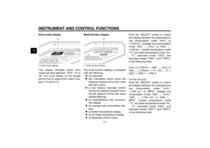 24
24 25
25 26
26 27
27 28
28 29
29 30
30 31
31 32
32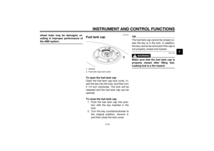 33
33 34
34 35
35 36
36 37
37 38
38 39
39 40
40 41
41 42
42 43
43 44
44 45
45 46
46 47
47 48
48 49
49 50
50 51
51 52
52 53
53 54
54 55
55 56
56 57
57 58
58 59
59 60
60 61
61 62
62 63
63 64
64 65
65 66
66 67
67 68
68 69
69 70
70 71
71 72
72 73
73 74
74 75
75 76
76 77
77 78
78 79
79 80
80 81
81 82
82 83
83 84
84 85
85 86
86 87
87 88
88 89
89 90
90 91
91 92
92 93
93 94
94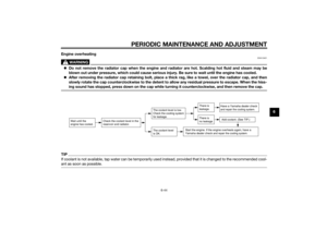 95
95 96
96 97
97 98
98 99
99 100
100 101
101 102
102 103
103 104
104 105
105 106
106 107
107
