Page 17 of 108

INSTRUMENT AND CONTROL FUNCTIONS
3-2
3
Keep other immo bilizer system
keys away from the main switch
as they may cause si gnal inter-
ference.
EAU10473
Main switch/steerin g lockThe main switch/steering lock controls
the ignition and lighting systems, and is
used to lock the steering. The various
positions are described below.TIPBe sure to use the standard key (black
bow) for regular use of the vehicle. To
minimize the risk of losing the code re-
registering key (red bow), keep it in a
safe place and only use it for code re-
registering.
EAU36871
ON
All electrical circuits are supplied with
power, the meter lighting, taillight, li-
cense plate light and auxiliary lights
come on, and the engine can be start-
ed. The key cannot be removed.TIPThe headlight comes on automatically
when the engine is started and stays
on until the key is turned to “OFF”,
even if the engine stalls.
EAU10662
OFF
All electrical systems are off. The key
can be removed.
WARNING
EWA10062
Never turn the key to “OFF” or
“LOCK” while the vehicle is movin g.
Otherwise the electrical systems will
b e switche d off, which may result in
loss of control or an acci dent.
P
ON
OFF
LOCK
U1RCE1E0.book Page 2 Wednesday, May 28, 2014 1:10 PM
Page 18 of 108

INSTRUMENT AND CONTROL FUNCTIONS
3-3
3
EAU10685
LOCK
The steering is locked, and all electrical
systems are off. The key can be re-
moved.
To lock the steering1. Turn the handlebars all the way tothe left.
2. Push the key in from the “OFF” position, and then turn it to
“LOCK” while still pushing it.
3. Remove the key. To unlock the steering
Push the key in, and then turn it to
“OFF” while still pushing it.
EAU59680
(Parkin
g)
The hazard lights and turn signal lights
can be turned on, but all other electri-
cal systems are off. The key can be re-
moved.
The steering must be locked before the
key can be turned to “ ”.
NOTICE
ECA20760
Usin g the hazar d o r t ur n s i gnal li ghts
for an exten ded len gth of time may
cause the battery to d ischarge.
EAU49396
In dicator li ghts and warning
li g hts
EAU11021
Turn si gnal in dicator li ght “ ”
This indicator light flashes when the
turn signal switch is pushed to the left
or right.
1. Push.
2. Turn.12
1. Push.
2. Turn.12
1. Neutral indicator light “ ”
2. High beam indicator light “ ”
3. Turn signal indicator light “ ”
4. Oil level warning light “ ”
5. Coolant temperature warning light “ ”
6. Engine trouble warning light “ ”
7. Anti-lock Brake System (ABS) warning light “ ” (for ABS models)
8. Immobilizer system indicator light “ ”
1
2
3
4
5
6
78
ABS
U1RCE1E0.book Page 3 Wednesday, May 28, 2014 1:10 PM
Page 19 of 108

INSTRUMENT AND CONTROL FUNCTIONS
3-4
3
EAU11061
Neutral indicator li ght “ ”
This indicator light comes on when the
transmission is in the neutral position.
EAU11081
Hi gh beam in dicator li ght “ ”
This indicator light comes on when the
high beam of the headlight is switched
on.
EAU11255
Oil level warnin g li ght “ ”
This warning light comes on if the en-
gine oil level is low.
The electrical circuit of the warning
light can be checked by turning the key
to “ON”. The warning light should
come on for a few seconds, and then
go off.
If the warning light does not come on
initially when the key is turned to “ON”,
or if the warning light remains on, have
a Yamaha dealer check the electrical
circuit.
TIP Even if the oil level is sufficient, the
warning light may flicker when rid-
ing on a slope or during sudden
acceleration or deceleration, but
this is not a malfunction.
This model is also equipped with a
self-diagnosis device for the oil
level detection circuit. If a problem
is detected in the oil level detec-
tion circuit, the following cycle will
be repeated until the malfunction
is corrected: The oil level warning
light will flash ten times, then go
off for 2.5 seconds. If this occurs,
have a Yamaha dealer check the
vehicle.
EAU11447
Coolant temperature warnin g
li g ht “ ”
This warning light comes on if the en-
gine overheats. If this occurs, stop the
engine immediately and allow the en-
gine to cool. The electrical circuit of the warning
light can be checked by turning the key
to “ON”. The warning light should
come on for a few seconds, and then
go off.
If the warning light does not come on
initially when the key is turned to “ON”,
or if the warning light remains on, have
a Yamaha dealer check the electrical
circuit.
NOTICE
ECA10022
Do not continue to operate the en-
g
ine if it is overheatin g.TIP For radiator-fan-equipped vehi-
cles, the radiator fan(s) automati-
cally switch on or off according to
the coolant temperature in the ra-
diator.
If the engine overheats, see page
6-44 for further instructions.
EAU46443
Engine trou ble warnin g li ght “ ”
This warning light comes on if a prob-
lem is detected in the electrical circuit
monitoring the engine. If this occurs,
U1RCE1E0.book Page 4 Wednesday, May 28, 2014 1:10 PM
Page 20 of 108

The electrical circuit of the warning
ligh")
INSTRUMENT AND CONTROL FUNCTIONS
3-5
3have a Yamaha dealer check the self-
diagnosis system. (See page 3-12 for
an explanation of the self-diagnosis
device.)
The electrical circuit of the warning
light can be checked by turning the key
to “ON”. The warning light should
come on for a few seconds, and then
go off.
If the warning light does not come on
initially when the key is turned to “ON”,
or if the warning light remains on, have
a Yamaha dealer check the electrical
circuit.
TIPThis warning light will come on when
the key is turned to “ON” and the start
switch is pushed, but this does not in-
dicate a malfunction.
EAU58530
ABS warnin
g li ght “ ” (for ABS
mo dels)
In normal operation, the ABS warning
light comes on when the key is turned
to “ON”, and goes off after traveling at
a speed of 10 km/h (6 mi/h) or higher.
If the ABS warning light:
does not come on when the key is
turned to “ON”
comes on or flashes while riding
does not go off after traveling at a
speed of 10 km/h (6 mi/h) or high-
er
The ABS may not work correctly. If any
of the above occurs, have a Yamaha
dealer check the system as soon as
possible. (See page 3-17 for an expla-
nation of the ABS.)
WARNING
EWA16041
If the ABS warnin g li ght does not g o
off after travelin g at a speed of 10
km/h (6 mi/h) or hi gher, or if the
warnin g li ght comes on or flashes
while ri din g, the brake system re-
verts to conventional brakin g. If ei-
ther of the ab ove occurs, or if the
warnin g li ght does not come on at
all, use extra caution to avoi d possi-
b le wheel lock d uring emer gency
b rakin g. Have a Yamaha d ealer
check the brake system an d electri-
cal circuits as soon as possi ble.
EAU54681
Immo bilizer system in dicator
li g ht “ ”
The electrical circuit of the indicator
light can be checked by turning the key
to “ON”. The indicator light should
come on for a few seconds, and then
go off.
If the indicator light does not come on
initially when the key is turned to “ON”,
or if the indicator light remains on, have
a Yamaha dealer check the electrical
circuit.
When the key is turned to “OFF” and
30 seconds have passed, the indicator
light will start flashing indicating the im-
mobilizer system is enabled. After 24
hours have passed, the indicator light
will stop flashing, however the immobi-
lizer system is still enabled.
The self-diagnosis device also detects
problems in the immobilizer system
circuits. (See page 3-12 for an expla-
nation of the self-diagnosis device.)
ABS
U1RCE1E0.book Page 5 Wednesday, May 28, 2014 1:10 PM
Page 21 of 108

INSTRUMENT AND CONTROL FUNCTIONS
3-6
3
EAU58054
Multi-function meter unit
WARNING
EWA12423
Be sure to stop the vehicle before
makin g any settin g chan ges to the
multi-function meter unit. Chan gin g
settin gs while ri din g can distract the
operator an d increase the risk of an
acci dent.The multi-function meter unit is
equipped with the following:
a speedometer
a tachometer
a clock
a fuel meter
an eco indicator
a transmission gear display
a drive mode display
a multi-function display
a self-diagnosis device
TIPBe sure to turn the key to “ON” be-
fore using the “SELECT” and “RE-
SET” buttons.
For the UK only: To switch the
speedometer and multi-function
displays between kilometers and
miles, press the “SELECT” button
for at least one second.
1. “SELECT” button
2. “RESET” button
2
1
1. Transmission gear display
2. Tachometer
3. Drive mode display
4. Fuel meter
5. Eco indicator “ECO”
6. Multi-function display
7. Clock
8. Speedometer
1
2
3
4
5
6
7
8
U1RCE1E0.book Page 6 Wednesday, May 28, 2014 1:10 PM
Page 22 of 108

INSTRUMENT AND CONTROL FUNCTIONS
3-7
3Speed
ometer
The speedometer shows the vehicle’s
traveling speed.
Tachometer The tachometer allows the rider to
monitor the engine speed and keep it
within the ideal power range.
When the key is turned to “ON”, the ta-
chometer will sweep across the r/min
range and then return to zero r/min in
order to test the electrical circuit.
NOTICE
ECA10032
Do not operate the en
gine in the ta-
chometer red zone.
Re d zone: 11250 r/min an d a boveClock
The clock displays when the key is
turned to “ON”. In addition, the clock
can be displayed for 10 seconds by pushing the “SELECT” button when
the main switch is in the “OFF”,
“LOCK” or “ ” position.
To set the clock
1. Turn the key to “ON”.
2. Push the “SELECT” button and
“RESET” button together for at
least two seconds.
3. When the hour digits start flash- ing, push the “RESET” button to
set the hours.
4. Push the “SELECT” button, and the minute digits will start flashing.
5. Push the “RESET” button to set the minutes.
6. Push the “SELECT” button and then release it to start the clock.
1. Speedometer
1. Tachometer
2. Tachometer red zone
1
2
1
1. Clock
1
U1RCE1E0.book Page 7 Wednesday, May 28, 2014 1:10 PM
Page 23 of 108
 as the fuel")
INSTRUMENT AND CONTROL FUNCTIONS
3-8
3
Fuel meter
The fuel meter indicates the amount of
fuel in the fuel tank. The display seg-
ments of the fuel meter disappear to-
wards “E” (Empty) as the fuel level
decreases. When the last segment and
fuel level warning indicator “ ” start
flashing, refuel as soon as possible.
TIPThis fuel meter is equipped with a self-
diagnosis system. If a problem is de-
tected in the electrical circuit, the fol-
lowing cycle is repeated until the
malfunction is corrected: fuel level seg-
ments and fuel level warning
indicator “ ” flash eight times, then go off for approximately 3 seconds. If this
occurs, have a Yamaha dealer check
the electrical circuit.
Eco in
dicator
This indicator comes on when the vehi-
cle is being operated in an environ-
mentally friendly, fuel-efficient manner.
The indicator goes off when the vehicle
is stopped.TIPConsider the following tips to reduce
fuel consumption: Avoid high engine speeds during
acceleration.
Travel at a constant speed.
Select the transmission gear that
is appropriate for the vehicle
speed.
Transmission gear display
This display shows the selected gear.
The neutral position is indicated by “ ”
and by the neutral indicator light.
1. Fuel meter
2. Fuel level warning indicator “ ”
1
2
1. Eco indicator “ECO”
1
1. Transmission gear display
2. Neutral indicator light “ ”
1
2
U1RCE1E0.book Page 8 Wednesday, May 28, 2014 1:10 PM
Page 24 of 108

INSTRUMENT AND CONTROL FUNCTIONS
3-9
3Drive mo
de display
This display indicates which drive
mode has been selected: “STD”, “A” or
“B”. For more details on the modes
and on how to select them, refer to pa-
ges 3-13 and 3-15. Multi-function
display
The multi-function display is equipped
with the following: an odometer
two tripmeters (which show the
distance traveled since they were
last set to zero)
a fuel reserve tripmeter (which
shows the distance traveled since
the left segment of the fuel meter
started flashing)
an instantaneous fuel consump-
tion display
an average fuel consumption dis-
play
a coolant temperature display
an air intake temperature display
a brightness control mode Push the “SELECT” button to switch
the display between the instantaneous
fuel consumption mode “km/L” or
“L/100 km”, average fuel consumption
mode “AVE_ _._ km/L” or “AVE_ _._
L/100 km”, coolant temperature mode
“°C”, air intake temperature mode “Air_
_ °C”, odometer mode “ODO”, and
tripmeter modes “TRIP 1” and “TRIP 2”
in the following order:
km/L or L/100 km
→ AVE_ _._ km/L or
AVE_ _._ L/100 km → °C → Air_ _ °C →
ODO → TRIP 1 → TRIP 2
For the UK only:
Push the “SELECT” button to switch
the display between the instantaneous
fuel consumption mode “km/L”,
“L/100 km” or “MPG”, average fuel
consumption mode “AVE_ _._ km/L”,
“AVE_ _._ L/100 km” or “AVE_ _._
MPG”, coolant temperature mode
“°C”, air intake temperature mode “Air_
_ °C”, odometer mode “ODO”, and
tripmeter modes “TRIP 1” and “TRIP 2”
in the following order:
1. Drive mode display
1
1. Multi-function display
1
U1RCE1E0.book Page 9 Wednesday, May 28, 2014 1:10 PM
 1
1 2
2 3
3 4
4 5
5 6
6 7
7 8
8 9
9 10
10 11
11 12
12 13
13 14
14 15
15 16
16 17
17 18
18 19
19 20
20 21
21 22
22 23
23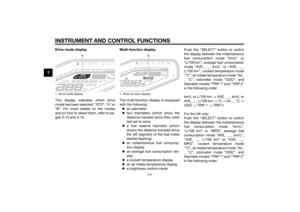 24
24 25
25 26
26 27
27 28
28 29
29 30
30 31
31 32
32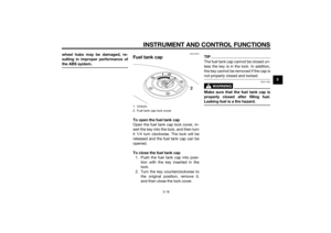 33
33 34
34 35
35 36
36 37
37 38
38 39
39 40
40 41
41 42
42 43
43 44
44 45
45 46
46 47
47 48
48 49
49 50
50 51
51 52
52 53
53 54
54 55
55 56
56 57
57 58
58 59
59 60
60 61
61 62
62 63
63 64
64 65
65 66
66 67
67 68
68 69
69 70
70 71
71 72
72 73
73 74
74 75
75 76
76 77
77 78
78 79
79 80
80 81
81 82
82 83
83 84
84 85
85 86
86 87
87 88
88 89
89 90
90 91
91 92
92 93
93 94
94 95
95 96
96 97
97 98
98 99
99 100
100 101
101 102
102 103
103 104
104 105
105 106
106 107
107