Page 89 of 108
 by
turning it counterclockwise.
3. Remove the burnt-out bulb by pulling it out. 4. Insert")
PERIODIC MAINTENANCE AND ADJUSTMENT
6-38
6
2. Remove the auxiliary light bulb
socket (together with the bulb) by
turning it counterclockwise.
3. Remove the burnt-out bulb by pulling it out. 4. Insert a new bulb into the socket.
5. Install the socket (together with
the bulb) by turning it clockwise.
6. Place the headlight unit side cov- ers in their original position, and
then install the bolts.
EAU24351
Supportin g the motorcycleSince this model is not equipped with a
centerstand, follow these precautions
when removing the front and rear
wheel or performing other mainte-
nance requiring the motorcycle to
stand upright. Check that the motorcy-
cle is in a stable and level position be-
fore starting any maintenance. A
strong wooden box can be placed un-
der the engine for added stability.
To service the front wheel
1. Stabilize the rear of the motorcy- cle by using a motorcycle stand
or, if an additional motorcycle
stand is not available, by placing a
jack under the frame in front of the
rear wheel.
2. Raise the front wheel off the ground by using a motorcycle
stand.
To service the rear wheel
Raise the rear wheel off the ground by
using a motorcycle stand or, if a motor-
cycle stand is not available, by placing
1. Bolt
2. Headlight unit side cover
1. Auxiliary light bulb socket1
1
2
2
1
1. Auxiliary light bulb
1
U1RCE1E0.book Page 38 Wednesday, May 28, 2014 1:10 PM
Page 90 of 108
PERIODIC MAINTENANCE AND ADJUSTMENT
6-39
6a jack either under each side of the
frame in front of the rear wheel or under
each side of the swingarm.
EAU44792
Front wheel (for non-ABS
mo
dels)
WARNING
EWA14841
For the ABS mo del, have a Yamaha
d ealer remove an d install the wheel.
EAU56270
To remove the front wheel
WARNING
EWA10822
To avoi d injury, securely support the
vehicle so there is no dan ger of it
fallin g over.1. Loosen the front wheel axle pinch
bolt, then the wheel axle and the
brake caliper bolts. 2. Lift the front wheel off the ground
according to the procedure in the
previous section “Supporting the
motorcycle”.
3. Remove the brake caliper on each side by removing the bolts.
NOTICE: Do not apply the b rake
after the brake calipers have
b een removed , otherwise the
b rake pa ds will b e forced shut.
[ECA11052]
1. Front wheel axle pinch bolt
2. Wheel axle
3. Brake caliper bolt
3
2
1
U1RCE1E0.book Page 39 Wednesday, May 28, 2014 1:10 PM
Page 91 of 108

PERIODIC MAINTENANCE AND ADJUSTMENT
6-40
6
4. Pull the wheel axle out, and then
remove the wheel.
To install the front wheel 1. Lift the wheel up between the fork legs.
2. Insert the wheel axle.
3. Install the brake calipers by install- ing the bolts.
TIPMake sure that there is enough space
between the brake pads before install-
ing the brake calipers onto the brake
discs.
4. Lower the front wheel so that it ison the ground, and then put the
sidestand down.
5. Tighten the wheel axle, the front wheel axle pinch bolt and the
brake caliper bolts to the specified
torques.
6. Push down hard on the handlebar several times to check for proper
fork operation.
EAU44802
Rear wheel (for non-ABS
mo dels)
WARNING
EWA14841
For the ABS mo del, have a Yamaha
d ealer remove an d install the wheel.
EAU56701
To remove the rear wheel
WARNING
EWA10822
To avoi d injury, securely support the
vehicle so there is no dan ger of it
fallin g over.1. Loosen the axle nut.
1. Brake caliper bolt
2. Brake caliper
12
Ti ghtenin g torques:
Wheel axle: 65 Nm (6.5 m·kgf, 47 ft·lbf)
Front wheel axle pinch bolt:
23 Nm (2.3 m·kgf, 17 ft·lbf)
Brake caliper bolt: 35 Nm (3.5 m·kgf, 25 ft·lbf)
1. Axle nut
1
U1RCE1E0.book Page 40 Wednesday, May 28, 2014 1:10 PM
Page 92 of 108

PERIODIC MAINTENANCE AND ADJUSTMENT
6-41
62. Lift the rear wheel off the ground
according to the procedure on
page 6-38.
3. Remove the axle nut.
4. Fully loosen the locknut on each side of the swingarm.
5. Turn the drive chain slack adjust- ing bolts fully in direction (a) and
push the wheel forward.
6. Remove the drive chain from the rear sprocket.
TIPIf the drive chain is difficult to re-
move, remove the wheel axle first,
and then lift the wheel upward
enough to remove the drive chain
from the rear sprocket.
The drive chain cannot be disas-
sembled.7. While supporting the brake caliper
bracket, pull the wheel axle out,
and then remove the wheel.
NOTICE: Do not apply the brake
after the wheel an d b rake disc
have been removed , otherwise
the brake pa ds will be forced
shut.
[ECA11073]
To install the rear wheel 1. Install the wheel and the brake cal- iper bracket by inserting the wheel
axle from the left-hand side.TIPMake sure that the slot in the
brake caliper bracket is fit over the
retainer on the swingarm.
Make sure that there is enough
space between the brake pads
before installing the wheel.2. Install the drive chain onto the rear
sprocket.
3. Install the axle nut.
1. Drive chain slack adjusting bolt
2. Locknut
(a)1
2
1. Wheel axle
1
1. Slot
2. Retainer
2
1
U1RCE1E0.book Page 41 Wednesday, May 28, 2014 1:10 PM
Page 93 of 108

6. Tighten the axle n")
PERIODIC MAINTENANCE AND ADJUSTMENT
6-42
6
4. Lower the rear wheel so that it is
on the ground, and then put the
sidestand down.
5. Adjust the drive chain slack. (See page 6-22.)
6. Tighten the axle nut, and then tighten the locknuts to the speci-
fied torques.
EAU25872
Trou bleshootin gAlthough Yamaha motorcycles receive
a thorough inspection before shipment
from the factory, trouble may occur
during operation. Any problem in the
fuel, compression, or ignition systems,
for example, can cause poor starting
and loss of power.
The following troubleshooting charts
represent quick and easy procedures
for checking these vital systems your-
self. However, should your motorcycle
require any repair, take it to a Yamaha
dealer, whose skilled technicians have
the necessary tools, experience, and
know-how to service the motorcycle
properly.
Use only genuine Yamaha replace-
ment parts. Imitation parts may look
like Yamaha parts, but they are often
inferior, have a shorter service life and
can lead to expensive repair bills.
WARNING
EWA15142
When checkin g the fuel system, d o
not smoke, an d make sure there are
no open flames or sparks in the ar-
ea, inclu din g pilot li ghts from water heaters or furnaces. Gasoline or
g
asoline vapors can i gnite or ex-
plo de, causin g severe injury or prop-
erty damag e.
Tightenin g torques:
Axle nut: 150 Nm (15 m·kgf, 108 ft·lbf)
Locknut:
16 Nm (1.6 m·kgf, 12 ft·lbf)
U1RCE1E0.book Page 42 Wednesday, May 28, 2014 1:10 PM
Page 94 of 108

PERIODIC MAINTENANCE AND ADJUSTMENT
6-43
6
EAU42365
Troubleshootin g chartsStartin g pro blems or poor en gine performance
Check the fuel level in
the fuel tank.1. Fuel
There is enough fuel.
There is no fuel.
Check the battery.
Supply fuel.
The engine does not start.
Check the battery.
Remove the spark plugs
and check the electrodes.3. Ignition
Wipe off with a dry cloth and correct the
spark plug gaps, or replace the spark plugs.
Have a Yamaha dealer check the vehicle.
Operate the electric starter.4. Compression
There is compression.
There is no compression.
The engine does not start.
Have a Yamaha dealer check the vehicle.Have a Yamaha dealer check the vehicle.
The engine does not start.
Check the compression.
Operate the electric starter.2. Battery
The engine turns over
quickly.
The engine turns over
slowly.
The engine does not start.
Check the ignition.
The battery is good.Check the battery lead connections,
and have a Yamaha dealer charge
the battery if necessary.
DryWet
Operate the electric starter.
U1RCE1E0.book Page 43 Wednesday, May 28, 2014 1:10 PM
Page 95 of 108

PERIODIC MAINTENANCE AND ADJUSTMENT
6-44
6
En
gine overheatin g
WARNING
EWA10401
Do not remove the ra diator cap when the en gine an d ra diator are hot. Scal din g hot flui d an d steam may be
b lown out un der pressure, which coul d cause serious injury. Be sure to wait until the en gine has coole d.
After removin g the ra diator cap retainin g b olt, place a thick ra g, like a towel, over the ra diator cap, an d then
slowly rotate the cap counterclockwise to the detent to allow any resid ual pressure to escape. When the hiss-
in g soun d has stopped , press down on the cap while turnin g it counterclockwise, an d then remove the cap.TIPIf coolant is not available, tap water can be temporarily used instead, provided that it is changed to the recommended cool-
ant as soon as possible.
Wait until the
engine has cooled.
Check the coolant level in the
reservoir and radiator.
The coolant level
is OK.The coolant level is low.
Check the cooling system
for leakage.
Have a Yamaha dealer checkand repair the cooling system.Add coolant. (See TIP.)
Start the engine. If the engine overheats again,
have a
Yamaha dealer check
and repair the cooling system.
There is
leakage.
There is
no leakage.
U1RCE1E0.book Page 44 Wednesday, May 28, 2014 1:10 PM
Page 96 of 108

MOTORCYCLE CARE AND STORAGE
7-1
7
EAU37834
Matte color cautionNOTICE
ECA15193
Some models are equipped with
matte colore d finishe d parts. Be
sure to consult a Yamaha d ealer for
a d vice on what prod ucts to use be-
fore cleanin g the vehicle. Usin g a
b rush, harsh chemical prod ucts or
cleanin g compoun ds when cleanin g
these parts will scratch or damag e
their surface. Wax also shoul d not
b e applied to any matte colore d fin-
ishe d parts.
EAU26015
CareWhile the open design of a motorcycle
reveals the attractiveness of the tech-
nology, it also makes it more vulnera-
ble. Rust and corrosion can develop
even if high-quality components are
used. A rusty exhaust pipe may go un-
noticed on a car, however, it detracts
from the overall appearance of a mo-
torcycle. Frequent and proper care
does not only comply with the terms of
the warranty, but it will also keep your
motorcycle looking good, extend its
life and optimize its performance.
Before cleanin g
1. Cover the muffler outlet with a plastic bag after the engine has
cooled down.
2. Make sure that all caps and cov- ers as well as all electrical cou-
plers and connectors, including
the spark plug caps, are tightly in-
stalled.
3. Remove extremely stubborn dirt, like oil burnt onto the crankcase,
with a degreasing agent and a
brush, but never apply such prod- ucts onto seals, gaskets, sprock-
ets, the drive chain and wheel
axles. Always rinse the dirt and
degreaser off with water.
Cleanin g
NOTICE
ECA10773
Avoi d using strong aci dic wheel
cleaners, especially on spoke d
wheels. If such prod ucts are
use d on har d-to-remove dirt, do
not leave the cleaner on the af-
fected area any lon ger than in-
structed . Also, thorou ghly rinse
the area off with water, imme di-
ately dry it, an d then apply a cor-
rosion protection spray.
Improper cleanin g can d amage
plastic parts (such as cowlin gs,
panels, win dshiel ds, hea dlig ht
lenses, meter lenses, etc.) an d
the mufflers. Use only a soft,
clean cloth or spon ge with wa-
ter to clean plastic. However, if
the plastic parts cannot b e thor-
ou ghly cleaned with water, di-
lute d mil d d eter gent with water
may be used . Be sure to rinse
U1RCE1E0.book Page 1 Wednesday, May 28, 2014 1:10 PM
 1
1 2
2 3
3 4
4 5
5 6
6 7
7 8
8 9
9 10
10 11
11 12
12 13
13 14
14 15
15 16
16 17
17 18
18 19
19 20
20 21
21 22
22 23
23 24
24 25
25 26
26 27
27 28
28 29
29 30
30 31
31 32
32 33
33 34
34 35
35 36
36 37
37 38
38 39
39 40
40 41
41 42
42 43
43 44
44 45
45 46
46 47
47 48
48 49
49 50
50 51
51 52
52 53
53 54
54 55
55 56
56 57
57 58
58 59
59 60
60 61
61 62
62 63
63 64
64 65
65 66
66 67
67 68
68 69
69 70
70 71
71 72
72 73
73 74
74 75
75 76
76 77
77 78
78 79
79 80
80 81
81 82
82 83
83 84
84 85
85 86
86 87
87 88
88 89
89 90
90 91
91 92
92 93
93 94
94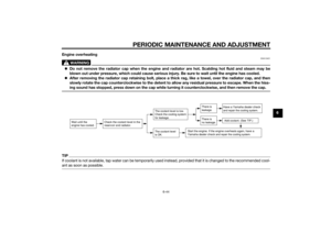 95
95 96
96 97
97 98
98 99
99 100
100 101
101 102
102 103
103 104
104 105
105 106
106 107
107
WARNING")