Page 185 of 232

Remove the wheel / fix186Follow-up tasks186
For your own safety and the safety of the passengers, the following instruc-
tions must be observed before changing a wheel on the road.
Switch on the hazard warning lights system.
Place the warning triangle at the prescribed distance.
Park the vehicle as far away as possible from flowing traffic.
Choose a location with a flat, solid surface.
Have all the occupants get out. The passengers should not stand on the
road (instead they should remain behind a crash barrier, for instance) while
the wheel is being changed.
Tyres with increased puncture resistance
Some vehicles may be fitted with tyres at the factory that have increased
puncture resistance (“SEAL” tyres).
These vehicles are delivered without a puncture repair kit, spare wheel and appropriate hand tools.
If tyres with increased puncture resistance are replaced with tyres that have
no increased puncture resistance, then the vehicle should be equipped with a
puncture repair kit, spare wheel and appropriate hand tools.
Preparation
Before changing the wheel, the following work must be carried out.
›
Switch off the engine.
›
For vehicles with manual transmission select 1st gear.
›
On vehicles with automatic transmission place the selector lever in the P po-
sition.
›
Firmly apply the handbrake.
›
Uncouple any trailers.
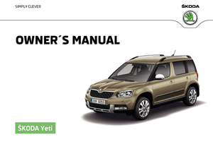
Removing/stowing the wheelFig. 180
Take out wheel
The spare wheel is located in a well under the floor covering in the boot and is
fixed in place with a fastening screw.
Take out wheel
›
Open the boot lid.
›
Raise the floor covering in the boot » page 102.
›
Loosen the belt and take out the box with the tool kit.
›
Unscrew the fastening screw in direction of arrow » Fig. 180.
›
Remove the wheel.
Store wheel away
›
Place the wheel into the spare wheel well with the wheel rim pointing up-
wards.
›
Pull the fixing band through the opposite holes in the wheel rim.
›
Screw on the fastening screw in the opposite direction to the arrow
» Fig. 180 until the wheel is safely secured.
›
Replace the box with the tool kit into the emergency or spare wheel and se-
cure it with the tape.
›
Fold back the floor in the luggage compartment.
›
Shut the boot lid.
Full wheel trim
Before removing the wheel bolts, remove the wheel cover.
Extracting
›
Hook the clamp found in the vehicle tool kit » page 182 into the reinforced
edge of the wheel trim.
›
Push the wheel wrench through the clamp, support on the tyre and pull off
the wheel trim.
183Emergency equipment and self-help
Page 186 of 232

Fitting›Press the wheel trim onto the wheel rim at the designated valve opening.›
Then press the trim into the wheel rim until its entire circumference locks
correctly in place.
Notes from the factory or from the ŠKODA Original accessory delivered trim.
▶ When using an anti-theft wheel bolt, make sure that this has been fitted ac-
cording to the position marked on the back of the wheel cover position.
▶ On the back of the wheel cover, the position for the anti-theft wheel bolt is
marked by means of a symbol. If the wheel cover is set outside the position
marked for the anti-theft wheel bolt, there is a risk of damaging the wheel
cover.
If wheel trims are fitted, an adequate flow of air must be assured in order to
cool the brake system.
CAUTION
Use the pressure of your hand only, do not strike the full wheel trim. The cover
could be damaged.
Note
We recommend that you use wheel trims from ŠKODA Original Accessories.
Wheel bolts
Fig. 181
Remove the cap
Before removing the wheel bolts, remove the covering caps.
Extracting
›
Push the extraction pliers » page 182 sufficiently far onto the cap until the
inner catches of the pliers are positioned at the collar of the cap.
›
Remove the cap in the direction of the arrow » Fig. 181.
Fitting
›
Push the caps onto the wheel bolts up to the stop.
Anti-theft wheel boltsFig. 182
Principle sketch: Anti-theft
wheel bolt with adapter
The anti-theft wheel bolts protect the wheels from theft. These can only be
loosened or tightened with the use of adapter
B
» Fig. 182 .
›
Remove the full wheel trim or the caps of the wheel bolts.
›
Insert adapter
B
» Fig. 182 with the toothed side all the way into the inner
teeth in the head of the anti-theft wheel bolts
A
.
›
Push the wheel wrench onto the adapter
B
up to the stop.
›
Loosen or tighten the wheel bolt » page 185.
›
Remove the adapter.
›
Replace the wheel trim or the caps.
To be equipped for a possible wheel change, the adapter for the anti-theft
wheel bolts must always be kept in the vehicle. The adapter is stowed in the
tool kit.
The position of the anti-theft wheel bolt is marked on the back of the wheel
cover with every ŠKODA supplied original equipment hub cap or directly at the
factors.
When using an anti-theft wheel bolt, make sure that this has been fitted ac-
cording to the position marked on the back of the wheel cover position.
Note
■ Note the code number which is embossed both on the adapter and also on
the end of each anti-theft wheel bolt. This number can be used to purchase a
replacement adapter from ŠKODA Original Parts if necessary.■
The anti-theft wheel bolt set and adapter can be purchased from a ŠKODA
Partner.
184Do-it-yourself
Page 187 of 232

Loosening/tightening wheel boltsFig. 183
Changing a wheel: Loosening the
wheel bolts
Before removing the wheel bolts, the caps for the wheel bolts must be pulled
off.
Release
›
Push the wheel wrench onto the wheel bolt until it locks into place.
Use the appropriate adapter for undoing the anti-theft wheel bolts » page 184.
›
Grasp the end of the wrench and turn the bolt about one turn in the direction
of the arrow » Fig. 183.
Tightening
›
Push the wheel wrench onto the wheel bolt until it locks into place.
Use the appropriate adapter for tightening the anti-theft wheel bolts
» page 184 .
›
Grasp the end of the wrench and turn the bolt against the direction of the
arrow » Fig. 183 , until it is tight.
After tightening the wheel bolts, the covering caps must be replaced.
WARNINGIf it proves difficult to undo the bolts, carefully apply pressure to the end of
the wrench with your foot. Keep hold of the vehicle when doing so, and
make sure you keep your footing.Raising the vehicleFig. 184
Jacking points for positioning
lifting jack
Fig. 185
Principle sketch: Attach lifting jack
Use the jack from the tool kit to raise the vehicle.
Position the car jack at the jacking point closest to the flat tyre .
The mounting points are located directly below the mark on the lower beam
» Fig. 184 .
›
Support the base plate of the jack with its full area resting on level ground
and ensure that the jack is located in a vertical position at the jacking point
» Fig. 185 -
.
›
Position the lifting jack below the jacking point with the crank and move it up
until its claw encloses the web » Fig. 185 -
.
›
Continue turning up the jack until the wheel is just about lifted off the
ground.
185Emergency equipment and self-help
Page 188 of 232

WARNING■If the wheel has to be changed on a slope, first of all block the opposite
wheel with a stone or similar object to prevent the vehicle from unexpect-
edly rolling away.■
Secure the base plate of the lifting jack with suitable means to prevent
possible moving. A soft and slippery ground under the base plate may move
the lifting jack, causing the vehicle to fall down. It is therefore always nec-
essary to place the lifting jack on a solid surface or use a wide and stable
base. If the surface is smooth, such as on cobbled stones, tiled floor, etc.,
use a non-slip base (e.g. a rubber foot mat).
■
Only attach the lifting jack to the attachment points provided for this pur-
pose.
■
Always raise the vehicle with the doors closed.
■
Never position any body parts, such as arms or legs under the vehicle,
while the vehicle is raised with a lifting jack.
■
When the vehicle is raised, never start the engine.
CAUTION
It is important to ensure that the jack is correctly attached to the web of the
lower fork leg - risk of damage to the vehicle.
Remove the wheel / fix
When changing a wheel, the following instructions must be followed.
›
Remove the full wheel trim or the caps of the wheel bolts.
›
First of all slacken the anti-theft wheel bolt and then the other wheel bolts.
›
Jack up the vehicle until the wheel that needs changing is clear of the
ground.
›
Unscrew the wheel bolts and place them on a clean surface (cloth, paper,
etc.).
›
Remove the wheel carefully.
›
Attach the wheel and slightly screw on the wheel bolts.
›
Lower the vehicle.
›
Tighten the wheel bolts opposite each other using the wheel wrench (alter-
nating crosswise). Tighten the anti-theft wheel bolt last.
›
Replace the wheel trim or the caps.
When fitting unidirectional tyres, ensure that the direction of rotation is cor-
rect » page 178 .
All bolts must be clean and must turn easily.
If it is established when changing a wheel that the wheel bolts are corroded and difficult to move, then these must be replaced.
Under no circumstances grease or oil the wheel bolts.WARNINGUndo the wheel bolts only a little (about one turn) as long as the vehicle
has not yet been jacked up. Otherwise the wheel could become loose and
fall off.
Follow-up tasks
After changing the wheel, the following work must be carried out.
›
Stow the replaced wheel in the wheel well and secure it with a special nut.
›
Stow the tool kit in the space provided and secure using the band.
›
Check the tyre pressure on the fitted wheel as soon as possible.
›
Have the tightening torque of the wheel bolts checked with a torque wrench
as soon as possible.
After changing the wheel, the tyre pressure should be adjusted. In vehicles
with tyre pressure monitoring, save tyre pressure values » page 141.
Replace the damaged wheel or consult a specialist garage about repair op-
tions.
The prescribed tightening torque of the wheel bolts is 120 Nm.
WARNING■
If the wheel bolts are tightened to a too low tightening torque, the rim
can come loose when the car is moving. A tightening torque which is too
high can damage the bolts and threads and this can result in permanent
deformation of the contact surfaces on the rim.■
Drive cautiously and only at a moderate speed until the tightening torque
has been checked.
Puncture repair kit
Introduction
This chapter contains information on the following subjects:
Components of the puncture repair kits
187
General information
187
186Do-it-yourself
Page 189 of 232

Preparations for using the breakdown kit188Sealing and inflating the tyre188
Notes for driving with repaired tyres
189
Use the breakdown kit to reliably repair tyre damage caused by foreign bodies
or a puncture with diameters up to approx. 4 mm.
Performing a repair with the breakdown kit not at all intended to replace a
permanent repair on the tyre. Its purpose is to get you to the nearest specialist
garage.
The wheel must not be removed during repair.
Do not remove foreign bodies that have penetrated the wheel profile from
the tyre (e.g. screws or nails).
Immediately replace the tyre that was repaired using the breakdown kit, or
consult a specialist garage about repair options.
WARNING■ The sealant is hazardous to heath. Remove immediately if it comes into
contact with the skin.■
Observe the manufacturer's usage instructions for the breakdown kit.
Note
A new bottle of sealant can be purchased from ŠKODA Original Parts.
Components of the puncture repair kits
Fig. 186
Principle sketch: Components of the breakdown kit
Read and observe on page 187 first.
Kit components » Fig. 186
Sticker with speed designation “max. 80 km/h”/“max. 50 mph”
Valve remover
Inflation hose with plug
12 volt cable connector
Tyre inflation pressure indicator
Air release valve
Air compressor
Tyre inflation hose
ON and OFF switch
Tyre inflator bottle with sealing agent
Replacement valve core
The valve remover
2
has a slot at its lower end which fits into the valve core.
The kit is located in a box under the floor covering in the luggage compart-
ment. The kit contains a sealant and an air compressor.
Note
The declaration of conformity is included with the air compressor or the log
folder.
General information
Read and observe
on page 187 first.
For your own safety and the safety of your passengers, the following instruc-
tions must be observed before carrying out a wheel repair on the road.
Switch on the hazard warning lights system.
Place the warning triangle at the prescribed distance.
Park the vehicle as far away as possible from flowing traffic.
Choose a location with a flat, solid surface.
Have all the occupants get out. The passengers should not stand on the
road (instead they should remain behind a crash barrier, for instance) while
the wheel is being changed.
The breakdown kit must not be used under the following circumstances. ▶ The rim is damaged.
▶ The outside temperature is below -20 ° C.
1234567891011187Emergency equipment and self-help
Page 190 of 232
.
Preparations for using the breakdown kit
Read and observe
on page 187")
▶The cut or puncture is larger than 4 mm.
▶ The tyre wall is damaged.
▶ After the expiration date (see inflation bottle).
Preparations for using the breakdown kit
Read and observe
on page 187 first.
The following preparatory work must be carried out before using the puncturerepair kit.
›
Switch off the engine.
›
For vehicles with manual transmission select 1st gear.
›
On vehicles with automatic transmission place the selector lever in the P po-
sition.
›
Firmly apply the handbrake.
›
Check that you can carry out the repairs with the breakdown kit » page 186.
›
Uncouple any trailers.
›
Remove the breakdown kit from the boot.
›
Stick the sticker
1
» Fig. 186 on page 187 on the dashboard in the driver's
field of view.
›
Unscrew the valve cap.
›
Use the valve remover
2
to unscrew the valve core and place it on a clean
surface (rag, paper, etc.).
Sealing and inflating the tyre
Read and observe
on page 187 first.
Sealing
›
Forcefully shake the tyre inflater bottle
10
» Fig. 186 on page 187 back and
forth several times.
›
Firmly screw the inflation hose
3
onto the tyre inflater bottle
10
. The film on
the cap is pierced automatically.
›
Remove the plug from the inflation hose
3
and plug the open end fully onto
the tyre valve.
›
Hold the bottle
10
with the bottom facing upwards and fill all of the sealing
agent from the tyre inflator bottle into the tyre.
›
Remove the filler plug from the tyre valve.
›
Screw the valve core back into the tyre valve using the valve remover
2
.
Inflating›Screw the air compressor tyre inflation hose 8 » Fig. 186 on page 187 firmly
onto the tyre valve.›
For vehicles with Manual transmission move the lever into the neutral posi-
tion and apply the parking brake firmly.
›
On vehicles with automatic transmission place the selector lever in the P po-
sition.
›
Check that the air release valve
6
is closed.
›
Start the engine and run it in idle.
›
Plug the connector
4
into 12 volt socket » page 88.
›
Switch on the air compressor with the ON and OFF switch
9
.
›
Allow the air compressor to run until a pressure of 2.0 - 2.5 bar is achieved.
Maximum run time of 8 minutes » .
›
Switch off the air compressor.
›
If you cannot reach an air pressure of 2.0 - 2.5 bar, unscrew the tyre inflation
hose
8
from the tyre valve.
›
Drive the vehicle 10 metres forwards or backwards to allow the sealing agent
to “distribute” in the tyre.
›
Firmly screw the tyre inflation hose
8
back onto the tyre valve and repeat
the inflation process.
›
Switch off the air compressor.
›
Remove the tyre inflation hose
8
from the tyre valve.
Once a tyre inflation pressure of 2.0 - 2.5 bar has been achieved, you can con- tinue the journey.
WARNING■ If the tyre does not inflate to at least. 2.0 bar, the damage is too great.
The sealing agent cannot be used to seal the tyre. Do not drive the vehi-
cle! Seek help from a specialist garage.■
The tyre inflation hose and air compressor may get hot as the tyre is be-
ing inflated – risk of burning.
CAUTION
Switch off the air compressor after running 8 minutes at the latest – risk of
overheating! Allow the air compressor to cool a few minutes before switching
it on again.188Do-it-yourself
Page 191 of 232

Notes for driving with repaired tyresRead and observe
on page 187 first.
The inflation pressure of the repaired tyre must be checked after driving for 10minutes.
If the tyre inflation pressure is 1.3 bar or less
›
Do not continue to drive! You cannot properly seal with tyre with the
breakdown kit.
If the tyre inflation pressure is 1.3 bar or more
›
Set the tyre pressure to the correct value.
›
Continue driving carefully to the nearest specialist garage at a maximum
speed of 80 km/h (50 mph).
WARNING■ A tyre filled with sealant has the same driving characteristics as a stand-
ard tyre.■
Do not drive faster than 80 km/h (50 mph).
■
Avoid accelerating at full throttle, sharp braking and fast cornering.
Jump-starting
Introduction
This chapter contains information on the following subjects:
Jump-starting using the battery from another vehicle
189
The battery of another vehicle can be used to jump-start your vehicle if the en-
gine will not start because the battery is flat.
WARNING■ Pay attention to the warning instructions relating to working in the en-
gine compartment » page 165.■
A discharged vehicle battery may already freeze at temperatures just be-
low 0 °C. If the battery is frozen, do not carry out a jump start with the bat-
tery of another vehicle – risk of explosion!
■
Keep any sources of ignition (naked flame, smouldering cigarettes, etc.)
away from the battery – risk of explosion!
WARNING (Continued)■ Never jump-start vehicle batteries with an electrolyte level that is too low
– risk of explosion and caustic burns.■
The vent screws of the battery cells must be tightened firmly.
Note
We recommend you buy jump-start cables from a car battery specialist.
Jump-starting using the battery from another vehicle
Fig. 187
Jump-starting: A – flat battery, B
– battery providing current
Fig. 188
Engine earth: START-STOP sys-
tem
Read and observe on page 189 first.
The starting process using the battery of another vehicle requires the use of
jumper cables.
The jump-start cables must be attached in the following sequence.
›
Attach clamp
1
to the positive terminal of the discharged battery
A
» Fig. 187 .
›
Attach clamp
2
to the positive terminal of the battery supplying power
B
.
›
Attach clamp
3
to the negative terminal of the battery supplying power
B
.
189Emergency equipment and self-help
Page 192 of 232

›Attach the clamp 4 to a solid metal part which is connected firmly to the en-
gine block or to the engine block itself.
The jump-start cable must be connected to the engine earthing point only on
vehicles with the START-STOP system » Fig. 188.
Starting engine›
Start the engine on the vehicle providing the power and allow it to idle.
›
Start the engine of the vehicle with the discharged battery.
›
If the engine does not start, terminate the attempt to start the engine after
10 seconds and wait for 30 seconds before repeating the process.
›
Remove the jump start cables in the reverse order as attachment.
Both batteries must have a rated voltage of 12 V. The capacity (Ah) of the bat-
tery supplying the power must not be significantly less than the capacity of
the discharged battery in your vehicle.
Jump-start cables
Only use jump-start cables which have an adequately large cross-section and
insulated terminal clamps. Observe the instructions of the jumper lead manu-
facturer.
Positive cable - colour coding in the majority of cases is red.
Negative cable - colour coding in the majority of cases is black.
WARNING■
Do not clamp the jump-start cable to the negative terminal of the dis-
charged battery. There is the risk of detonating gas seeping out the battery being ignited by the strong spark which results from the engine being star-
ted.■
The non-insulated parts of the terminal clamps must never touch each
other – risk of short circuit!
■
The jump-start cable connected to the positive terminal of the battery
must not come into contact with electrically conducting parts of the vehicle
– risk of short circuit!
■
Route the jump-start cables so that they cannot be caught by any rotat-
ing parts in the engine compartment.
Towing the vehicle
Introduction
Fig. 189
Braided tow rope / Spiral tow rope
This chapter contains information on the following subjects:
Front towing eye
191
Rear towing eye
192
Vehicles with a tow hitch
192
For towing, a braided tow rope is to be used » Fig. 189 -
.
When towing, the following guidelines must be observed.
Vehicles with manual transmission may be towed in with a tow bar or a tow
rope or with the front or rear wheels raised.
Vehicles with Automatic transmission may be towed in with a tow bar or a
tow rope or with the front wheels raised. If the vehicle is raised at rear, the au-
tomatic gearbox is damaged! If possible, the vehicle should be towed with the
engine running or at least with the ignition on.
Driver of the tow vehicle
›
Engage the clutch gently when starting off or depress the accelerator partic-
ularly gently if the vehicle is fitted with an automatic gearbox.
›
Only then approach correctly when the rope is taut.
The maximum towing speed is 50 km/h.
Driver of the towed vehicle
›
Switch on the ignition so that the steering wheel is not locked and so that
the turn-signal lights, windscreen wipers and windscreen washer system can
be used.
190Do-it-yourself
 1
1 2
2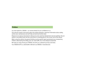 3
3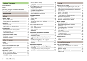 4
4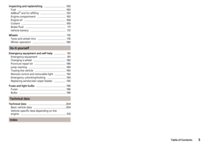 5
5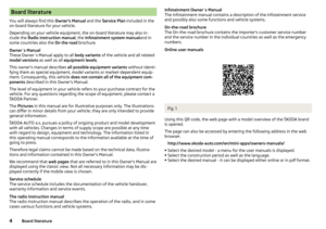 6
6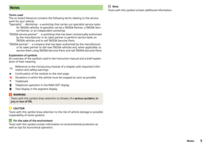 7
7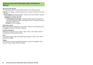 8
8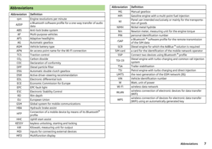 9
9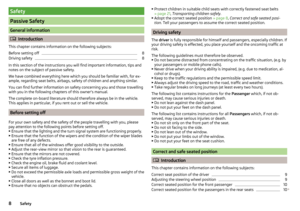 10
10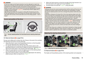 11
11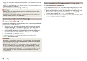 12
12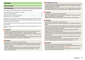 13
13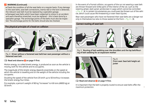 14
14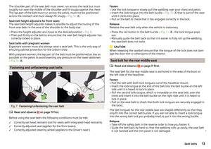 15
15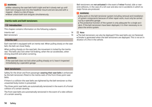 16
16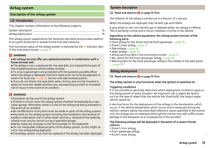 17
17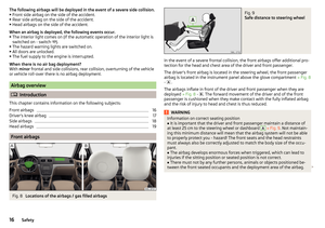 18
18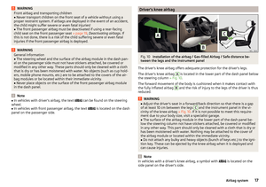 19
19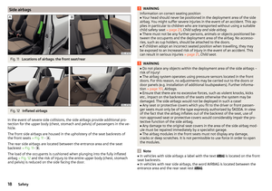 20
20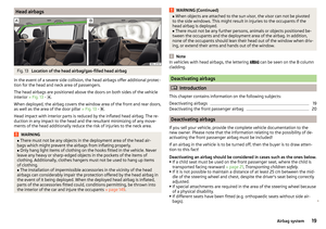 21
21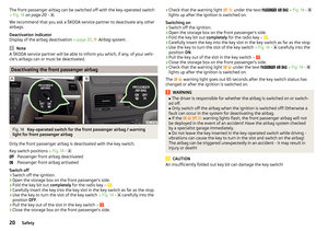 22
22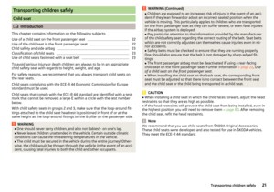 23
23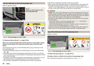 24
24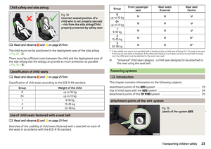 25
25 26
26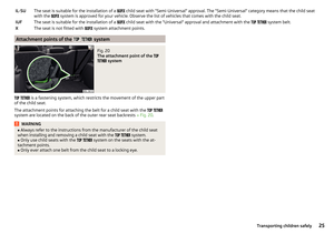 27
27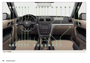 28
28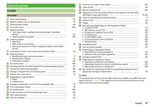 29
29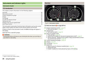 30
30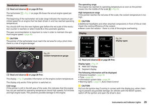 31
31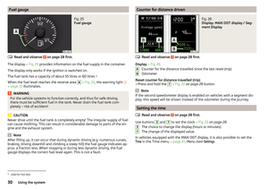 32
32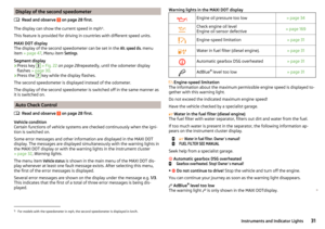 33
33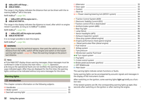 34
34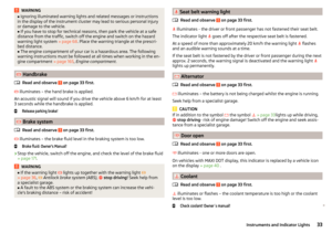 35
35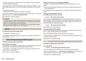 36
36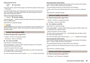 37
37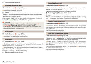 38
38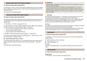 39
39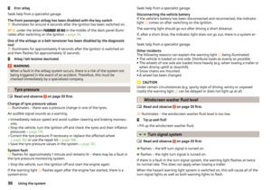 40
40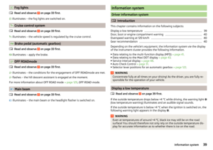 41
41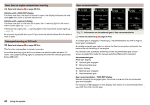 42
42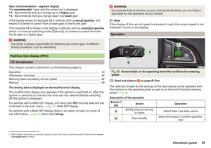 43
43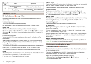 44
44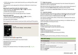 45
45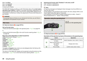 46
46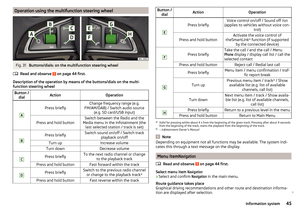 47
47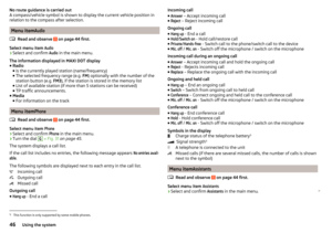 48
48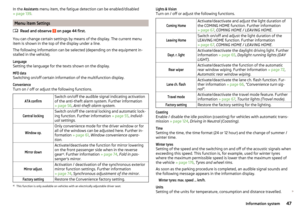 49
49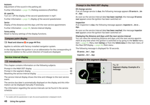 50
50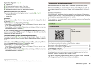 51
51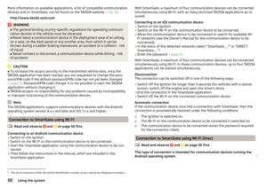 52
52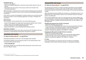 53
53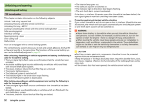 54
54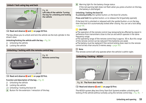 55
55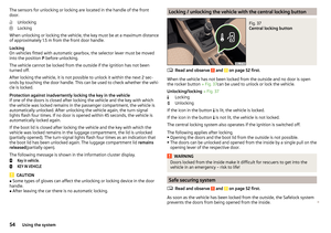 56
56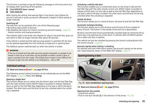 57
57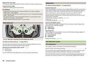 58
58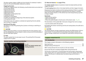 59
59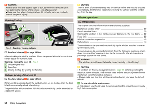 60
60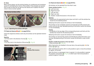 61
61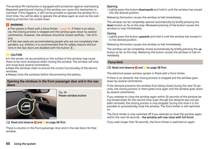 62
62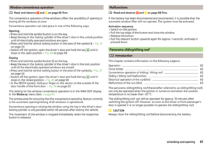 63
63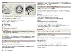 64
64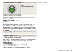 65
65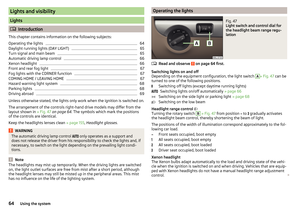 66
66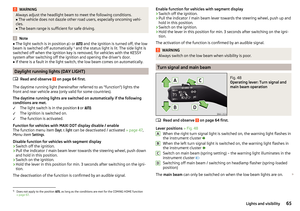 67
67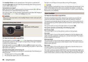 68
68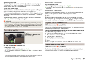 69
69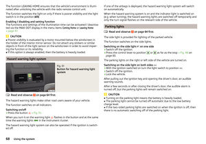 70
70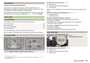 71
71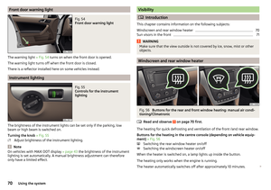 72
72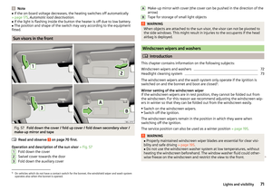 73
73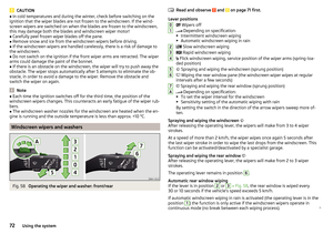 74
74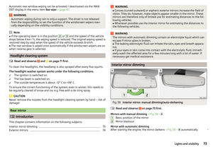 75
75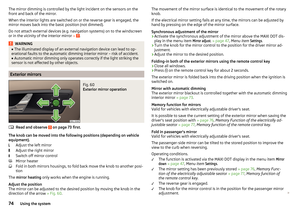 76
76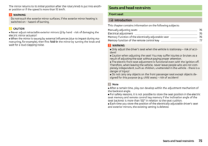 77
77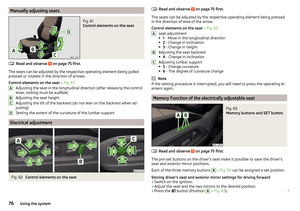 78
78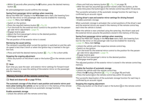 79
79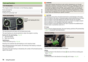 80
80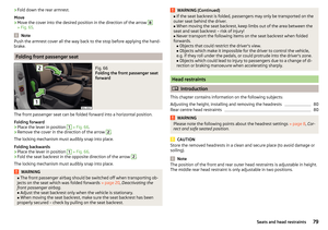 81
81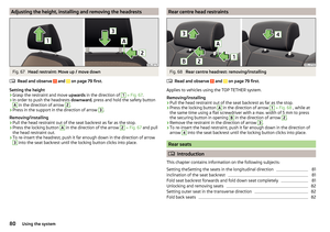 82
82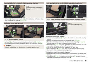 83
83 84
84 85
85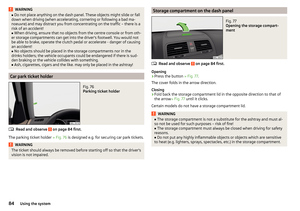 86
86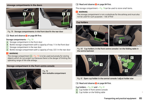 87
87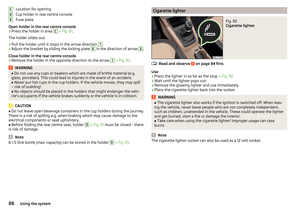 88
88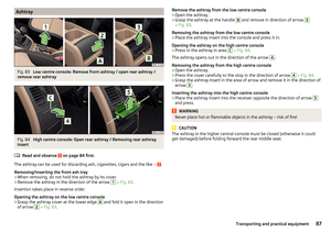 89
89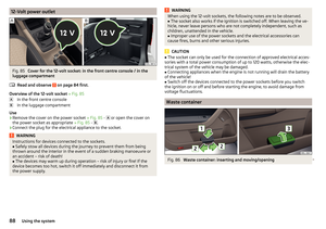 90
90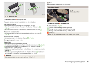 91
91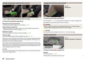 92
92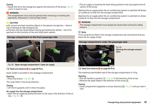 93
93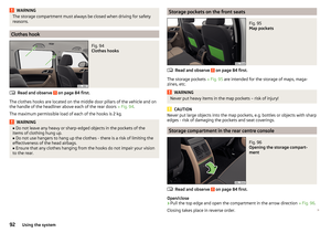 94
94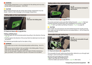 95
95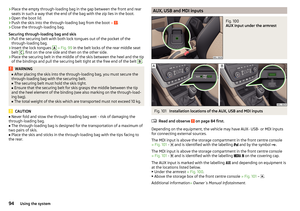 96
96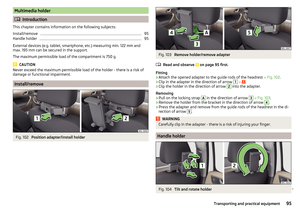 97
97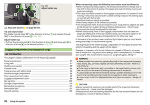 98
98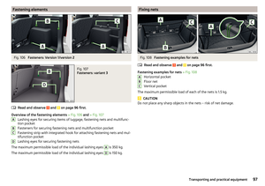 99
99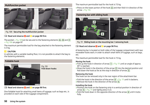 100
100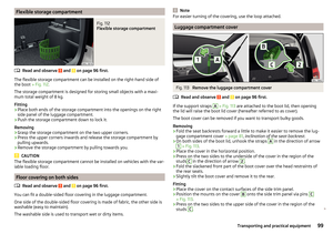 101
101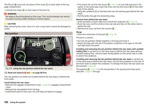 102
102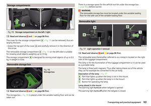 103
103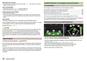 104
104 105
105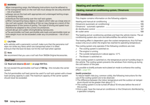 106
106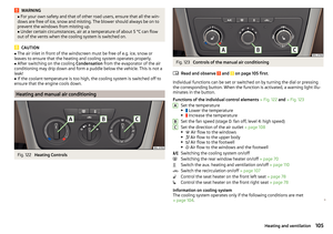 107
107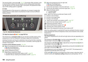 108
108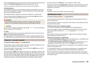 109
109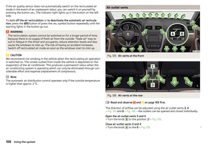 110
110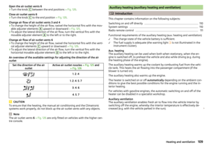 111
111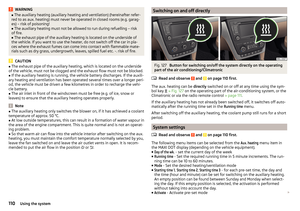 112
112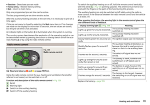 113
113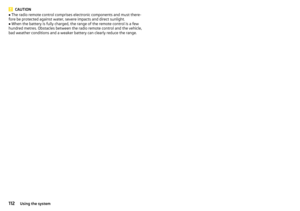 114
114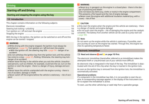 115
115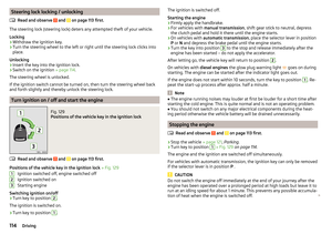 116
116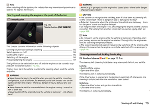 117
117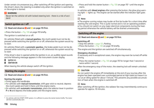 118
118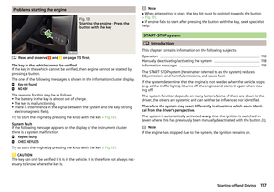 119
119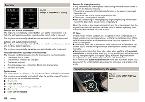 120
120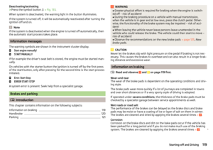 121
121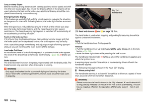 122
122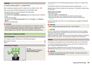 123
123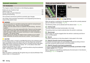 124
124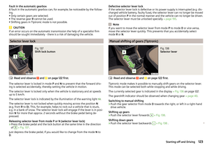 125
125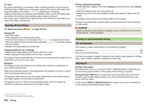 126
126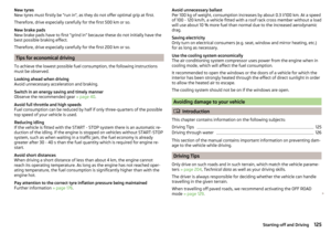 127
127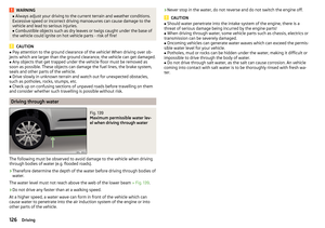 128
128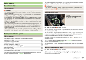 129
129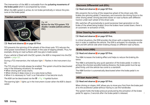 130
130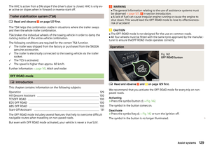 131
131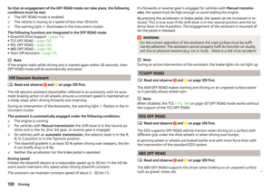 132
132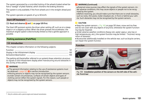 133
133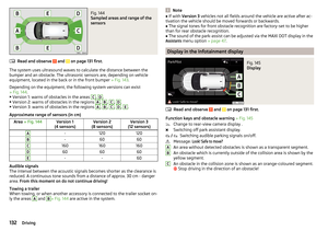 134
134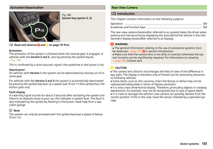 135
135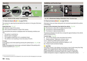 136
136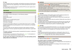 137
137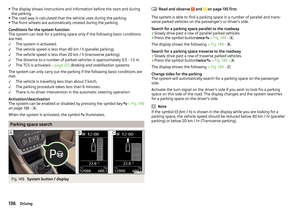 138
138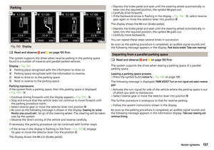 139
139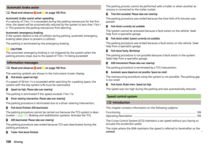 140
140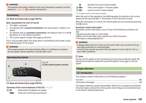 141
141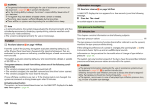 142
142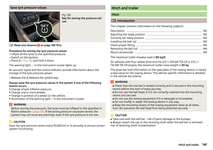 143
143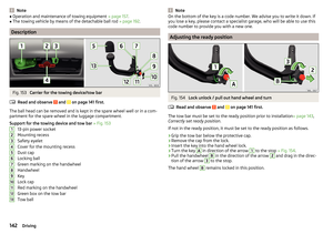 144
144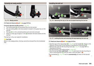 145
145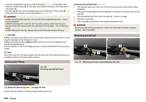 146
146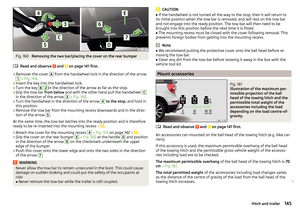 147
147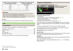 148
148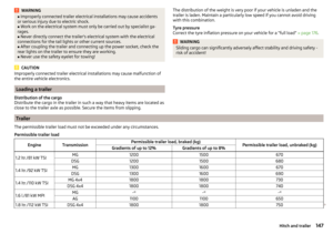 149
149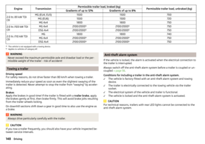 150
150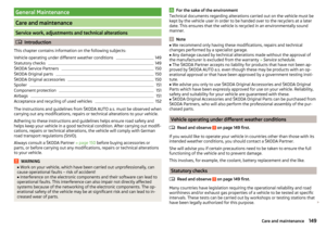 151
151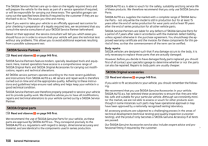 152
152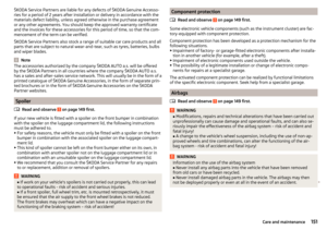 153
153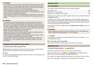 154
154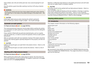 155
155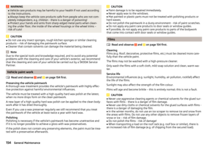 156
156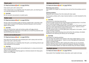 157
157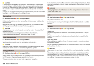 158
158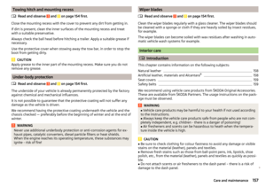 159
159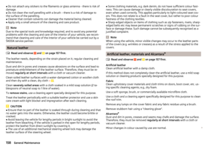 160
160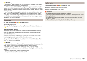 161
161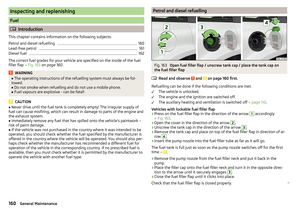 162
162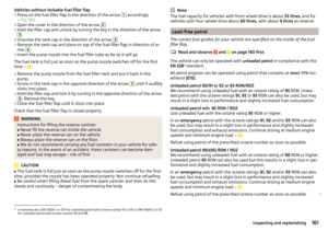 163
163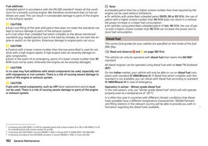 164
164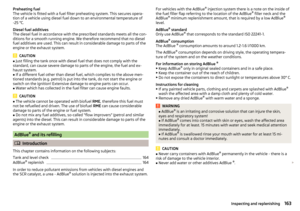 165
165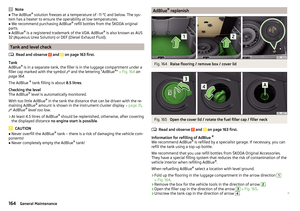 166
166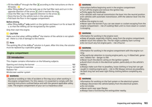 167
167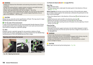 168
168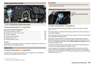 169
169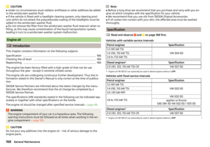 170
170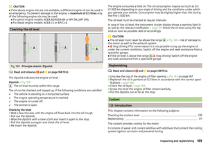 171
171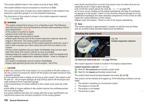 172
172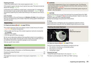 173
173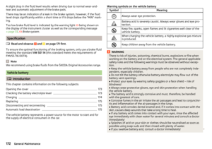 174
174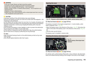 175
175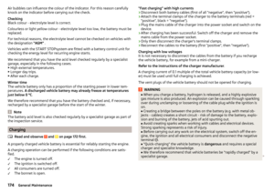 176
176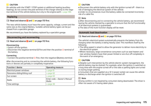 177
177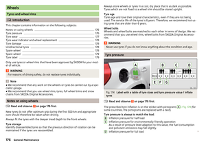 178
178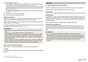 179
179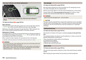 180
180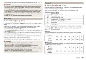 181
181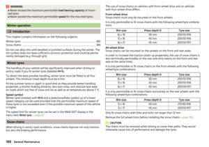 182
182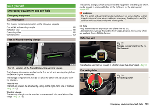 183
183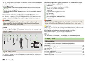 184
184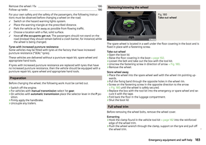 185
185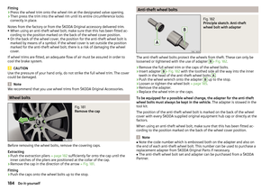 186
186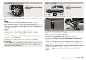 187
187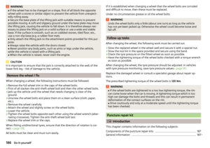 188
188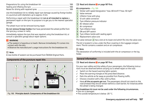 189
189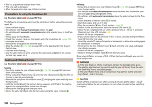 190
190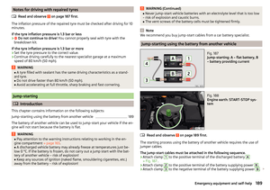 191
191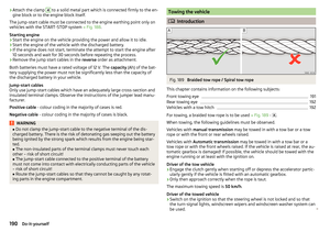 192
192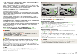 193
193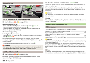 194
194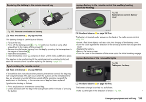 195
195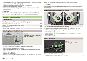 196
196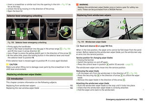 197
197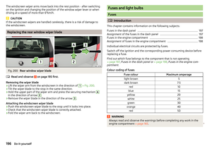 198
198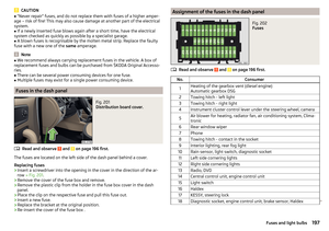 199
199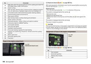 200
200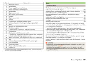 201
201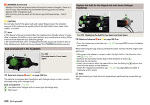 202
202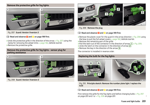 203
203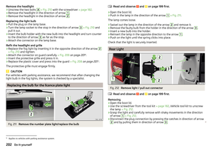 204
204 205
205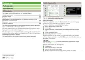 206
206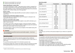 207
207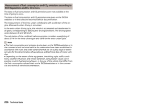 208
208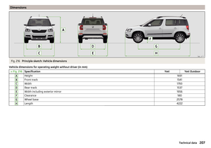 209
209 210
210 211
211 212
212 213
213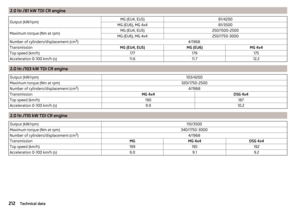 214
214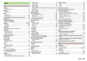 215
215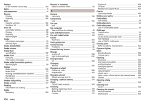 216
216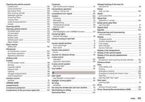 217
217 218
218 219
219 220
220 221
221 222
222 223
223 224
224 225
225 226
226 227
227 228
228 229
229 230
230 231
231