Page 137 of 232

Note■The orientation lines are immobile, and therefore the spacing of the bars be-
hind the vehicle will vary, depending on the vehicle load state and the road in-
clination.■
If reduced park assistance display is switched off the acoustic signal cannot
be turned off with the button
.
Park Assist
Introduction
This chapter contains information on the following subjects:
Functioning
135
Parking space search
136
Parking
137
Departing from a parallel parking space
137
Automatic brake assist
138
Information messages
138
Park Assist (hereinafter referred to as system) helps drivers park in suitable
parallel and perpendicular parking places or also to manoeuvre out of parallel
parking spaces.
The system takes over the steering movements when parking or leaving a
parking space. The driver operates the pedals and the shift lever or gear selec-
tor.
The state in which the steering wheel is operated by the system, is referred to
as parking operation.
The Park Assist is an extension of the parking aid » page 131 and operates on
the basis of data collected by the ultrasonic sensors.
For this reason, the chapter on the parking aid is to be read carefully and the safety notes are to be observed.
WARNING■ The general information relating to the use of assistance systems must
be observed » page 127, in section Introduction .■
During the parking process, the system automatically performs rapid
steering movements. While it is doing so, do not place your hands between
the steering wheel – risk of injury!
■
During a parking manoeuvre on loose or slippery surfaces (gravel, snow,
ice, etc.) you may stray from the calculated road. Therefore we suggest that
you do not use the system in such situations.
CAUTION
The correct evaluation of the parking space and the parking procedure de-
pends on the circumference of the wheels on the vehicle.■
The system only works correctly if the vehicle is fitted with the wheel size
approved by the manufacturer.
■
Abstain from using the system when the vehicle is fitted with snow chains or
a temporary spare wheel.
■
If wheels other than those approved by the manufacturer are mounted, the
resulting position of the vehicle in the parking space can differ slightly. This
can be avoided by readjusting the system at a specialist garage.
CAUTION
If other vehicles are parked behind the kerb or on it, the system can also guide
your vehicle beyond the kerb or onto it. Ensure that the wheels or the wheel
rims of your vehicle are not damaged and if necessary intervene in time.
Note
■ We recommend performing the parking at a safe speed to about 5 km / h.■The driver can stop the parking process at any time by pressing the symbol
key
» Fig. 149 on page 136 or by a driver steering intervention.
Functioning
Read and observe
and on page 135 first.
The system support is provided in the following manner.▶ While the parking space search is going on, a measurement and evaluation of
the parking space size is completed.
▶ Suitable parking spaces are shown in the display of the instrument cluster
(hereinafter only in the display).
135Assist systems
Page 138 of 232

▶The display shows instructions and information before the start and during
the parking.
▶ The road way is calculated that the vehicle uses during the parking.
▶ The front wheels are automatically rotated during the parking.
Conditions for the system function
The system can look for a parking space only if the following basic conditions
are met.
The system is activated.
The vehicle speed is less than 40 km / h (parallel parking).
The vehicle speed is less than 20 km / h (transverse parking).
The distance to a number of parked vehicles is approximately 0.5 - 1.5 m.
The TCS is activated » page 127, Braking and stabilisation systems .
The system can only carry out the parking if the following basic conditions are
met.
The vehicle is travelling less than about 7 km/h.
The parking procedure takes less than 6 minutes.
There is no driver intervention in the automatic steering operation.
Activation/deactivation
The system can be enabled or disabled by pressing the symbol key
» Fig. 149
on page 136 -
.
When the system is activated, the symbol illuminates.
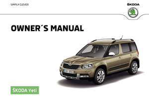
Parking space search
Fig. 149
System button / display
Read and observe and on page 135 first.
The system is able to find a parking space in a number of parallel and trans-
verse parked vehicles on the passenger's or driver's side.
Search for a parking space parallel to the roadway
›
Slowly drive past a row of parallel parked vehicles.
›
Press the symbol button once
» Fig. 149 -
.
The display shows the following » Fig. 149 -
.
Search for a parking space traverse to the roadway
›
Slowly drive past a row of traverse parked vehicles.
›
Press the symbol button twice
» Fig. 149 -
.
The display shows the following » Fig. 149 -
.
Change sides for the parking
The system will automatically search for a parking space on the passenger
side.
Activate the turn signal on the driver's side if you wish to look fro a parking
space on this side of the road. The display changes and the system searches
for a parking space on the driver's side.
Note
If the symbol (km / h) is shown in the display while you are looking for a
parking space, the vehicle speed should be reduced below 40 km / hr (parallel parking) or below 20 km / hr (Transverse parking).136Driving
Page 139 of 232

ParkingFig. 150
Display
Read and observe
and on page 135 first.
The system supports the driver when reverse parking in the parking space
found in a number of traverse and parallel parked vehicles.
Display » Fig. 150
Parking place recognised with the information to drive on.
Parking space recognised with the information to reverse.
Note to drive on to the parking space.
Note to reverse to the parking space.
Parking manoeuvre
If the system finds a parking space, then this parking space is displayed
» Fig. 150 -
.
›
Continue driving forwards until the display appears
» Fig. 150 -
.
›
Stop and ensure that the vehicle does not continue to move forward until
the parking procedure starts.
›
Select reverse gear or move the selector lever into position R.
›
As soon as the following message is shown in the display:
Steering int. active.Monitor area around veh.!
, let go of the steering wheel. The steering will be taken
over by the system.
›
Observe the direct vicinity of the vehicle and reverse carefully.
If necessary, the parking procedure can be continued with further steps.
›
If the arrow in the display is flashing to the front » Fig. 150
, engage
1st gear or move the selector lever into the position D.
The display shows the icon (brake pedal).
›Depress the brake pedal and wait until the steering wheel automatically ro-
tates into the required position, the symbol goes out.›
Carefully drive forwards.
›
If the backwards arrow is flashing in the display » Fig. 150 -
, select reverse
gear again or move the selector lever into position R .
The display shows the
icon (brake pedal).
›
Depress the brake pedal and wait until the steering wheel automatically ro-
tates into the required position, the symbol
goes out.
›
Carefully move backwards.
You can repeat these steps several times in succession.
As soon as the parking procedure is completed, an audible signal sounds and
the following message appears in the display:
Park Assist ended. Take over steering!
Departing from a parallel parking space
Read and observe
and on page 135 first.
The system supports the driver when leaving a parking space of a parallel
parking space.
Leaving a parking space process
›
Press the symbol button once
» Fig. 149 on page 136 .
The following message is displayed:
PARK ASSIST Turn on turn signal and select reversegear.›
Activate the turn signal for side of the vehicle where the parking space is out
of which you wish to manoeuvre.
›
Select reverse gear or move the selector lever into position R.
The further procedure is analogous to that for reverse parking.
›
Follow the system instructions shown in the display.
As soon as the parking procedure is completed, an audible signal sounds and
the following message appears in the information display:
Take over steering andcontinue driving.137Assist systems
Page 140 of 232

Automatic brake assistRead and observe
and on page 135 first.
Automatic brake assist when speeding
If a velocity of 7 km / h is exceeded during the parking manoeuvre for the first
time, the speed will be automatically reduced by the system to less than 7 km /
h. This prevents the parking manoeuvre from aborting.
Automatic emergency braking
If the system detects a risk of collision during parking, automatic emergency
braking takes place to prevent a collision.
The parking is terminated by the emergency braking.
CAUTION
The automatic emergency braking is not triggered by the system when the
parking process stops due to the speed of 7 km / hr being exceeded!
Information messages
Read and observe
and on page 135 first.
The warning symbols are shown in the instrument cluster display.
Park Assist: speed too high.
If a speed of 50 km / h is exceeded while searching for a parking space, the
system with the key symbol is must be reactivated.
Speed too high. Please take over steering!
The parking is terminated if the speed exceeds 7 km / hr.
Driver steering intervention: Please take over steering!
The parking procedure is terminated due to a driver steering intervention.
Park Assist finished. ASR deactivated.
The parking procedure cannot be carried out because the TCS system is deac-
tivated » page 127 , Braking and stabilisation systems . Activate the TCS.
ASR deactivated. Please take over steering!
The parking procedure was ended because TCS was deactivated during the
parking procedure.
Trailer: Park Assist finished.The parking process cannot be performed with a trailer or when another ac-
cessory is connected to the trailer socket.Time limit exceeded. Please take over steering!
The parking procedure was ended because the time limit of 6 minutes was
passed.
Park Assist currently not available.
The system cannot be activated because a fault exists on the vehicle. Seek
help from a specialist garage.
Park Assist ended. System currently not available.
The parking procedure was ended because a fault exists on the vehicle. Seek
help from a specialist garage.
Park Assist faulty. Workshop!
The parking procedure is not possible because a fault exists in the system.
Seek help from a specialist garage.
ASR intervention! Please take over steering!
The parking procedure is terminated by a TCS intervention.
Automatic space departure not possible. Space too small.
The manoeuvring procedure using the system is not possible. The parking gap
is too small.
Park Assist: Brake interv. Speed too high.
The speed was too high during the parking and was automatically reduced.
Speed control system
Introduction
This chapter contains information on the following subjects:
Functioning
139
Operating Description
139
The Cruise Control System (CCS) maintains a set speed without you having to
actuate the accelerator pedal.
The state where the GRA maintains the speed is referred to hereinafter as the
control .
138Driving
Page 141 of 232

WARNINGThe general information relating to the use of assistance systems must be
observed » page 127, in section Introduction .
Functioning
Read and observe
on page 139 first.
Basic requirements for start of control The GRA is activated.
On vehicles with a manual transmission , the second gear or higher is en-
gaged.
On vehicles with an automatic transmission , the selector lever is in the D,
S position or in the Tiptronic position.
The current speed is higher than approx. 20 km/h.
This is only possible within the range which is permitted by the power output and braking power of the engine.
WARNINGIf the engine power and engine braking effect is insufficient to maintain
the set speed, vehicle operation must be taken over!
Operating Description
Fig. 151
Cruise control system controls
Read and observe on page 139 first.
Overview of the control elements of the CCS » Fig. 151ADeactivate CCS (delete set speed) Interrupt control (sprung position) Activate CCS (control deactivated)BTake control again a)
/ Increase speedCLaunch control / reduce speeda)
If no speed is set the current speed is adopted.
After the start of the regulation, the GRA regulates the vehicle to the current
speed and the warning light
illuminates in the instrument cluster.
After the interruption in control, the stored speed can be resumed by pressing
the
B
button.
Automatic control interruption
Automatic control interruption occurs if any of the following conditions are
met.
▶ By pressing the brake or clutch pedal.
▶ When one of the brake assist systems (e.g. ESC) intervenes.
▶ Through an airbag deployment.
WARNING■ Always deactivate the cruise control system after use to prevent the sys-
tem being switched on unintentionally.■
Control may only be resumed if the set speed is not too high for the cur-
rent traffic conditions.
Note
During control, speed can be increased by pressing the accelerator pedal. Re-
leasing the accelerator pedal will cause the speed to drop again to the set
speed.
Fatigue detection
Introduction
This chapter contains information on the following subjects:
Function
140
Information messages
140
The fatigue detection system (hereinafter referred to as system) recommends
the driver takes a break from driving when driver fatigue can be detected due
to the driver's steering behaviour.
139Assist systems
Page 142 of 232

WARNING■The general information relating to the use of assistance systems must
be observed » page 127, in section Introduction .■
For the driving ability is always the driver's responsibility. Never drive if
you feel tired.
■
The system may not detect all cases where a break is needed.
■
Therefore, take regular, sufficient breaks during long trips.
■
There will be no system warning during the so-called micro-sleep.
Note
■ In some situations, the system may evaluate the driving incorrectly and thus
mistakenly recommend a break (e.g. sporty driving, adverse weather condi-
tions or poor road conditions).■
The system is designed primarily for use on motorways.
Function
Read and observe
on page 140 first.
From the start of the journey, the system evaluates steering behaviour. If,
while driving, there have been changes in the steering behaviours that are
evaluated by the system as indicating possible fatigue, a break recommenda-
tion is issued.
The system evaluates steering behaviour and recommends a break at speeds
of 65-200 km / h.
The system detects a break from driving when one of the following condi-
tions is met.
▶ The vehicle is stopped and the ignition switched off.
▶ The vehicle is stopped, the seat belt removed and the driver's door opened.
▶ The vehicle is stopped for more than 15 minutes.
If none of these conditions are met or if the driving style is not changed, the
system recommends a driving break again after 15 minutes.
Activation/deactivation
The system can be activated/deactivated via the MAXI DOT display in the
Assis-tants
menu option » page 44.
Information messages
Read and observe
on page 140 first.
In MAXI DOT display the icon appears for a few seconds and the following
message.
Driver alert.
Take a break!
An audible signal is also emitted.
Tyre pressure monitoring
Introduction
This chapter contains information on the following subjects:
Save tyre pressure values
141
The tyre pressure monitoring function (hereinafter referred to as the system)
monitors the tyre pressure while driving.
If the rolling circumference of a wheel is changed, the warning light in the
instrument cluster lights up and an audible signal sounds.
Information on the procedure for the notification of change of tyre inflation
pressure » page 38 .
The system can only function properly if the tyres have the prescribed inflation
pressure and these pressure values are stored in the system.
WARNING■ The general information relating to the use of assistance systems must
be observed » page 127, in section Introduction .■
Having the correct tyre inflation pressure is always the driver's responsi-
bility. Tyre pressure should be checked regularly » page 176.
■
The system cannot warn in case of very rapid tyre inflation pressure loss,
e.g. in case of sudden tyre damage.
140Driving
Page 143 of 232

Save tyre pressure valuesFig. 152
Key for storing the pressure val-
ues
Read and observe on page 140 first.
Procedure for storing the tyre pressure values
›
Inflate all the tyres to the specified pressure.
›
Switch on the ignition.
›
Press
» Fig. 152 and hold it down.
The warning light in the instrument cluster lights up.
An acoustic signal and the control indicator provide information about the
storage of the tyre pressure values.
›
Release the Release the symbol key.
Always save the tyre pressure values in the system if one of the following
events occurs.
▶ Change of tyre inflation pressure.
▶ Change one or more wheels.
▶ Change in position of a wheel on the vehicle.
▶ Illumination of the warning light in the instrument cluster.
WARNINGBefore storing the pressures, the tyres must be inflated to the specified in-
flation pressure » page 176. If the wrong pressure valuesare stored, the
system may not issue any warnings, even if the tyre pressure is too low.
CAUTION
Save the tyre pressure values every 10,000 km or 1x annually to ensure correct
system functioning.Hitch and trailer
Hitch
Introduction
This chapter contains information on the following subjects:
Description
142
Adjusting the ready position
142
Correctly set ready position
143
Installing the ball rod
143
Check proper fitting
144
Removing the ball rod
144
Mount accessories
145
The maximum trailer drawbar load is 80 kg/h.
On vehicles with four-wheel drive and the 2.0 l / 103 kW TDI CR or 2.0 L /
110 kW TDI CR engine, the maximum trailer nose weight is 85 kg .
The draw bar load information on the type plate of the towing device is merely
a test value for the towing device. The vehicle-specific information is detailed
in the vehicle documents.
WARNING■ Check that the tow bar is seated correctly and is secured in the mounting
recess before the start of every journey.■
Do not use the ball head, if it is not correctly inserted into the mounting
recess and secured.
■
Do not use the towing equipment if it is damaged or incomplete.
■
Do not modify or adapt the towing device in any way.
■
Keep the mounting recess of the towing equipment clean at all times.
Such dirt prevents the ball head from being attached securely.
CAUTION
■ Take care with the ball bar - risk of paint damage to the bumper.■Always attach the cap to the receiving shaft when the ball bar is removed -
risk of receiving-shaft contamination. 141Hitch and trailer
Page 144 of 232

Note■Operation and maintenance of towing equipment » page 157.■The towing vehicle by means of the detachable ball rod » page 192.
Description
Fig. 153
Carrier for the towing device/tow bar
Read and observe
and on page 141 first.
The ball head can be removed and is kept in the spare wheel well or in a com-
partment for the spare wheel in the luggage compartment.
Support for the towing device and tow bar » Fig. 153
13-pin power socket
Mounting recess
Safety eyelet
Cover for the mounting recess
Dust cap
Locking ball
Green marking on the handwheel
Handwheel
Key
Lock cap
Red marking on the handwheel
Green box on the tow bar
Tow ball
12345678910111213NoteOn the bottom of the key is a code number. We advise you to write it down. If
you lose a key, please contact a specialist garage, who will be able to use this
code number to provide you with a new one.
Adjusting the ready position
Fig. 154
Lock unlock / pull out hand wheel and turn
Read and observe
and on page 141 first.
The tow bar must be set to the ready position prior to installation » page 143,
Correctly set ready position .
If not in the ready position, it must be set to the ready position as follows.
›
Grip the tow bar below the protective cap.
›
Remove the cap from the lock.
›
Insert the key into the hand wheel lock.
›
Turn the key
A
in direction of the arrow
1
to the stop » Fig. 154.
›
Pull the handwheel
B
in the direction of the arrow
2
and drag in the direc-
tion of the arrow
3
to the stop.
The hand wheel
B
remains locked in this position.
142Driving
 1
1 2
2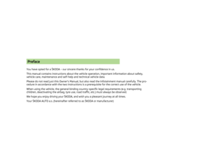 3
3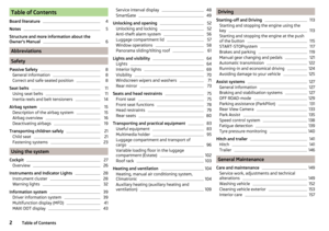 4
4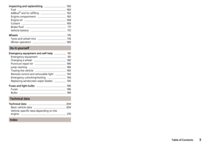 5
5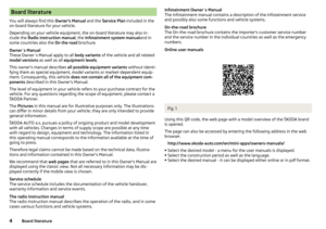 6
6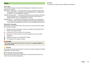 7
7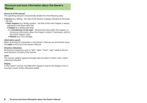 8
8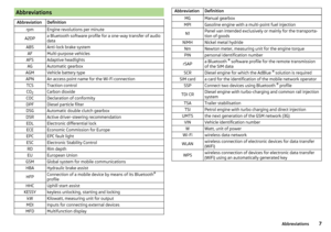 9
9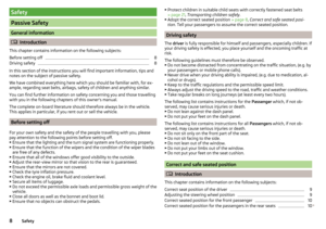 10
10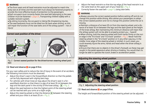 11
11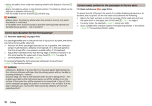 12
12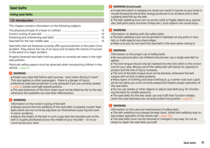 13
13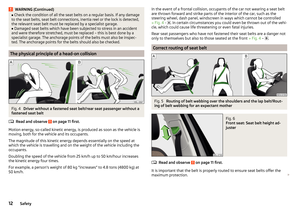 14
14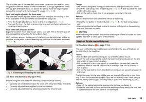 15
15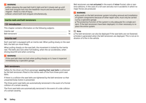 16
16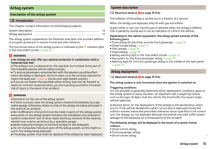 17
17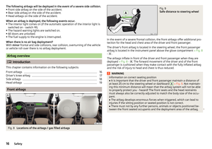 18
18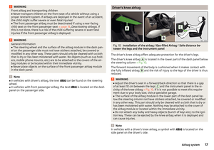 19
19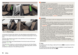 20
20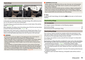 21
21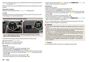 22
22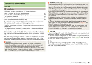 23
23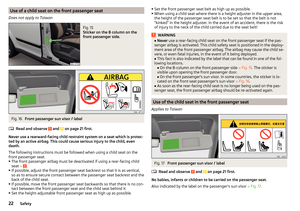 24
24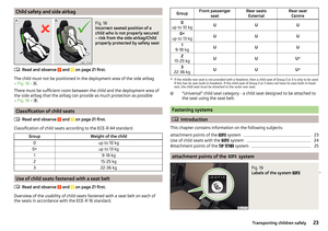 25
25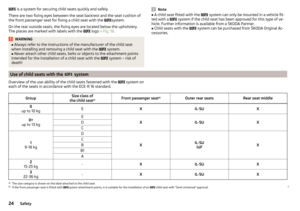 26
26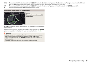 27
27 28
28 29
29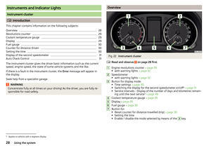 30
30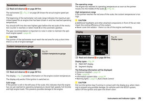 31
31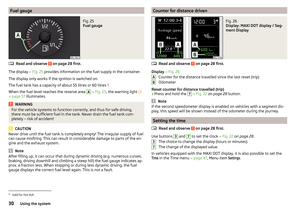 32
32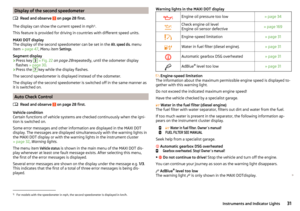 33
33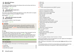 34
34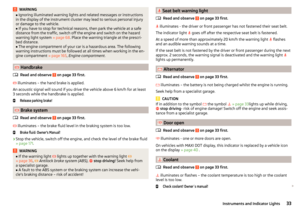 35
35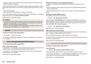 36
36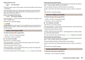 37
37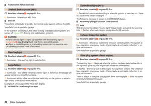 38
38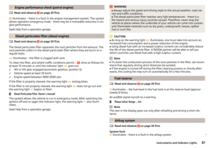 39
39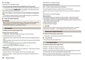 40
40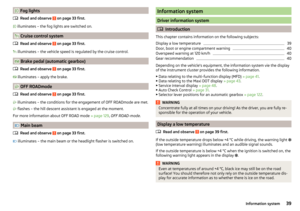 41
41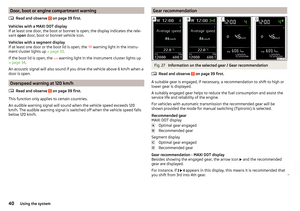 42
42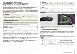 43
43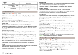 44
44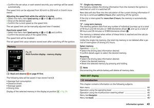 45
45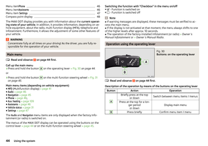 46
46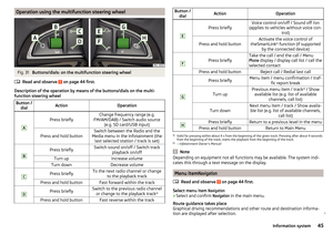 47
47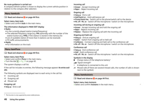 48
48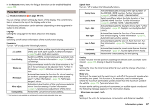 49
49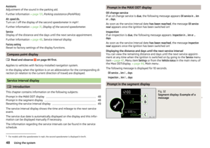 50
50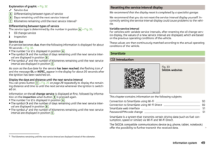 51
51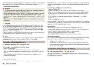 52
52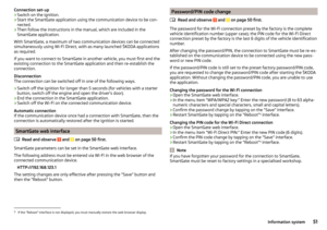 53
53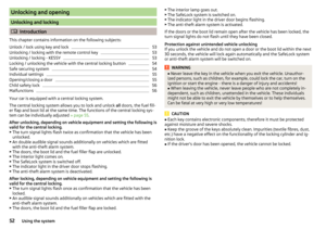 54
54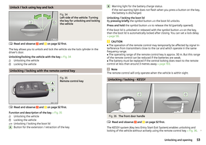 55
55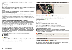 56
56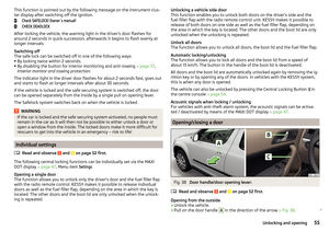 57
57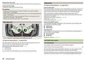 58
58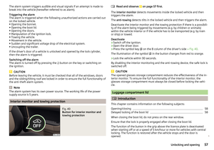 59
59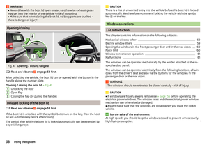 60
60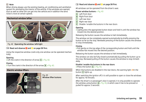 61
61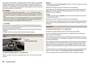 62
62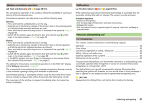 63
63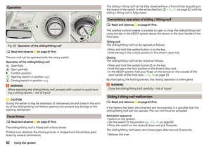 64
64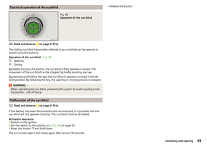 65
65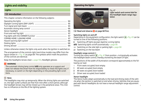 66
66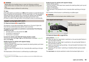 67
67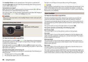 68
68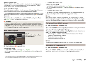 69
69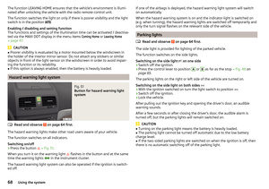 70
70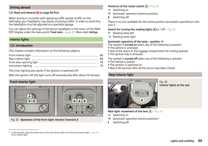 71
71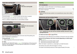 72
72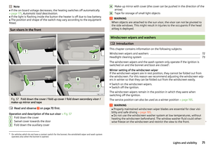 73
73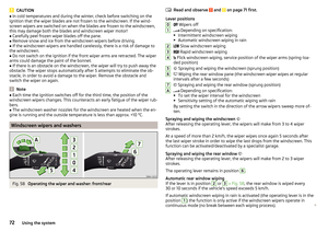 74
74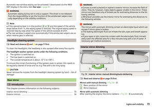 75
75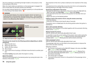 76
76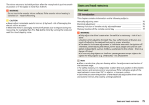 77
77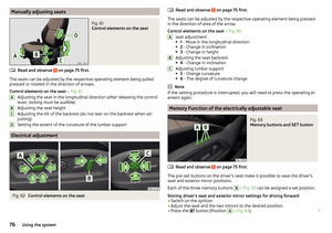 78
78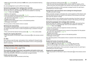 79
79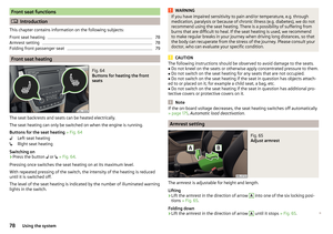 80
80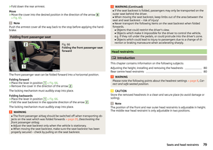 81
81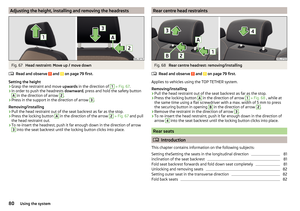 82
82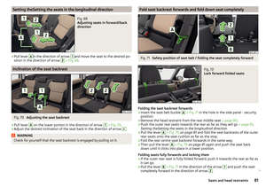 83
83 84
84 85
85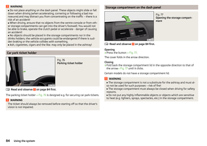 86
86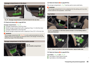 87
87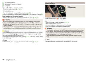 88
88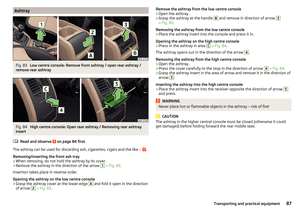 89
89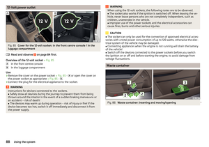 90
90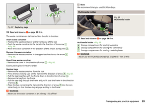 91
91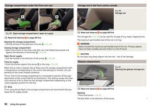 92
92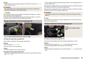 93
93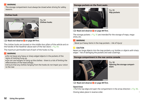 94
94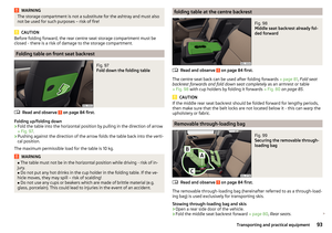 95
95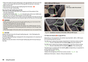 96
96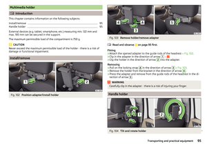 97
97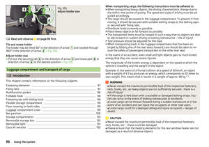 98
98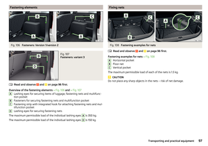 99
99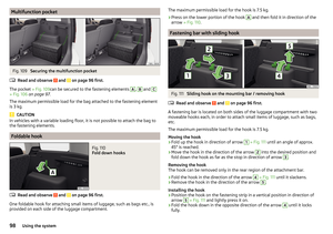 100
100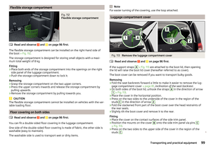 101
101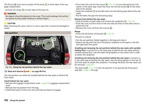 102
102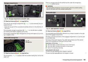 103
103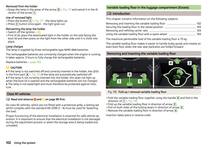 104
104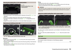 105
105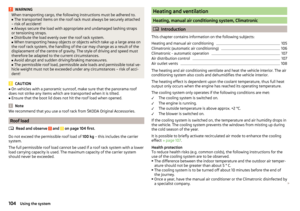 106
106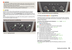 107
107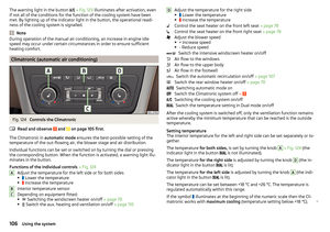 108
108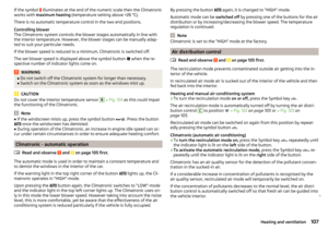 109
109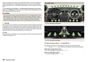 110
110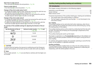 111
111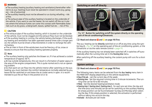 112
112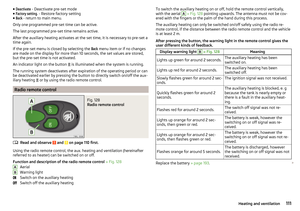 113
113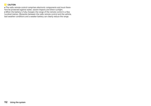 114
114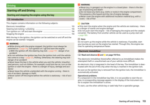 115
115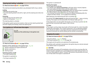 116
116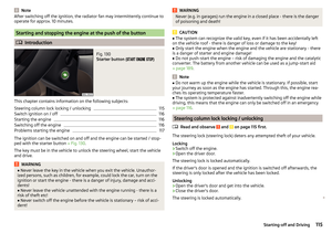 117
117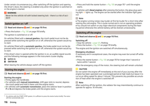 118
118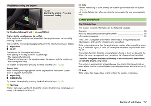 119
119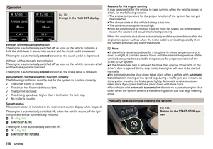 120
120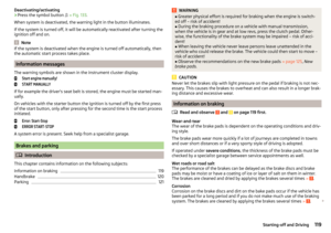 121
121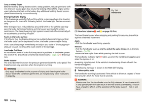 122
122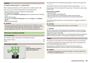 123
123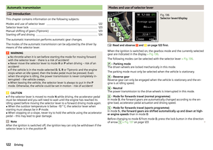 124
124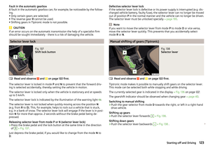 125
125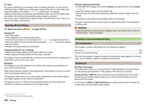 126
126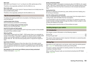 127
127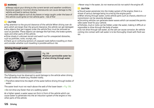 128
128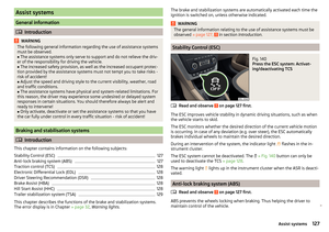 129
129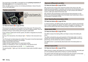 130
130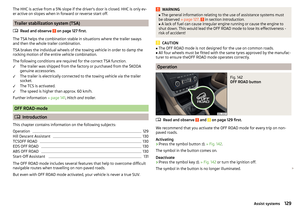 131
131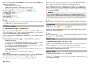 132
132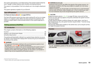 133
133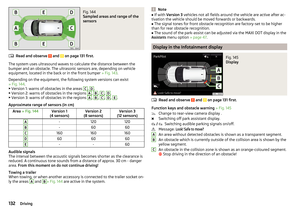 134
134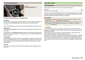 135
135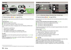 136
136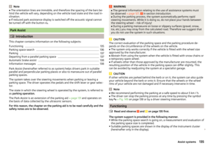 137
137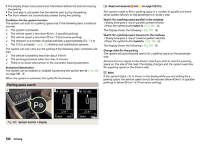 138
138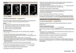 139
139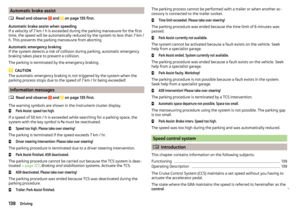 140
140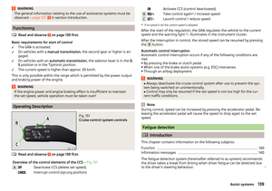 141
141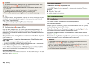 142
142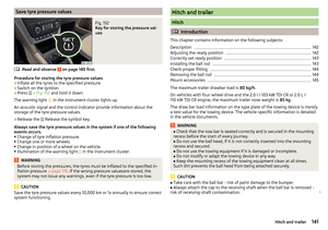 143
143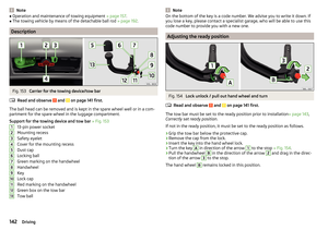 144
144 145
145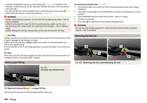 146
146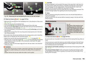 147
147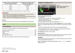 148
148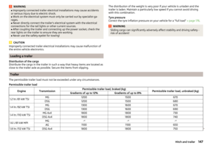 149
149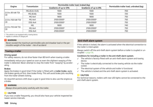 150
150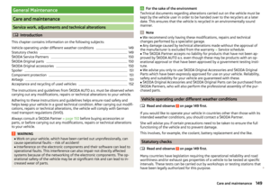 151
151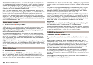 152
152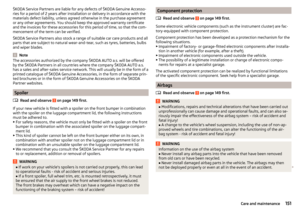 153
153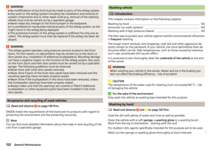 154
154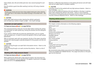 155
155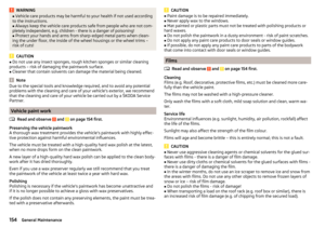 156
156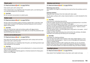 157
157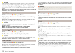 158
158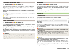 159
159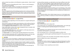 160
160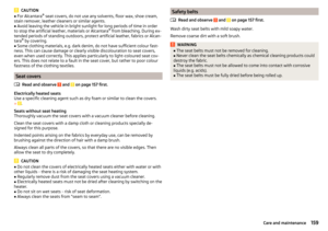 161
161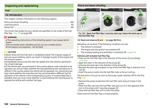 162
162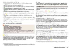 163
163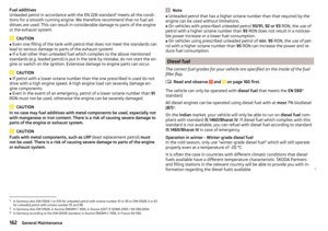 164
164 165
165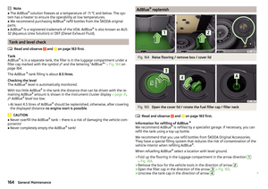 166
166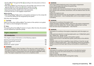 167
167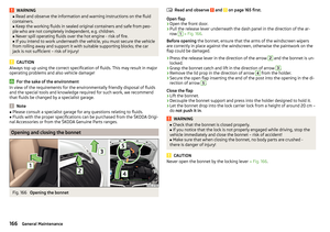 168
168 169
169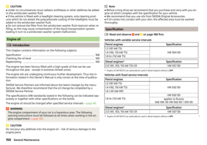 170
170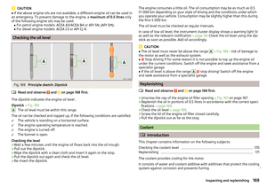 171
171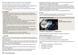 172
172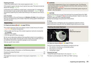 173
173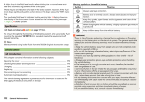 174
174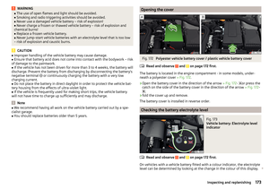 175
175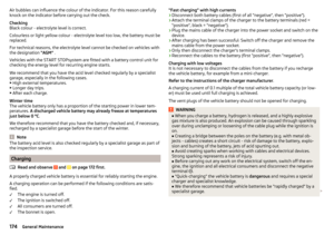 176
176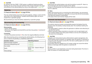 177
177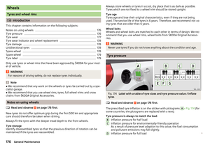 178
178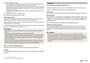 179
179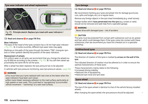 180
180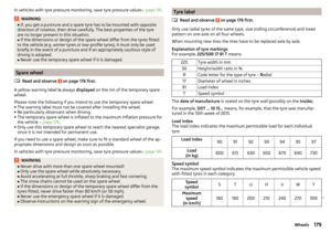 181
181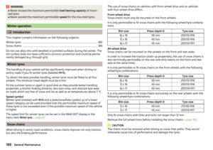 182
182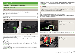 183
183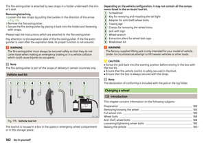 184
184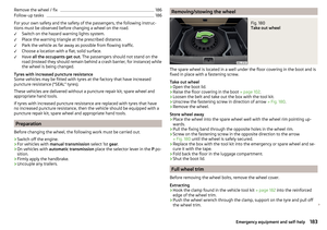 185
185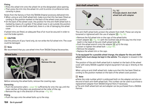 186
186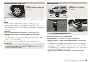 187
187 188
188 189
189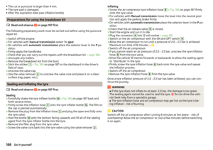 190
190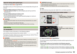 191
191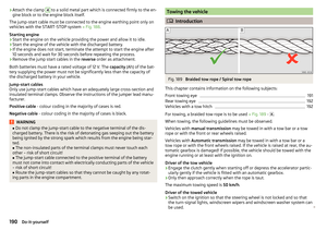 192
192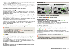 193
193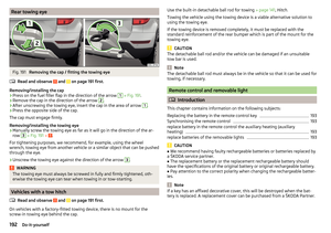 194
194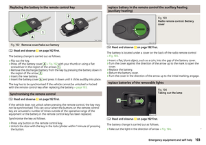 195
195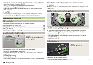 196
196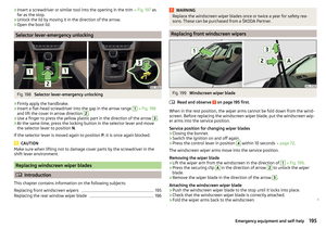 197
197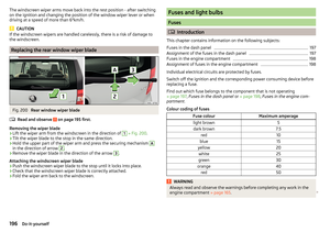 198
198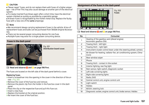 199
199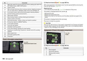 200
200 201
201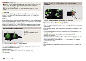 202
202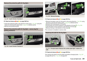 203
203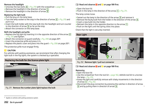 204
204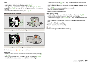 205
205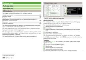 206
206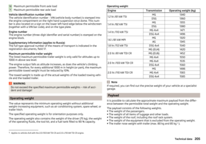 207
207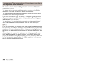 208
208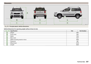 209
209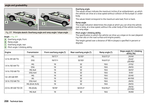 210
210 211
211 212
212 213
213 214
214 215
215 216
216 217
217 218
218 219
219 220
220 221
221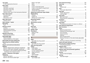 222
222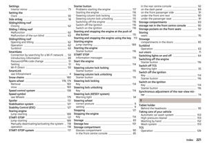 223
223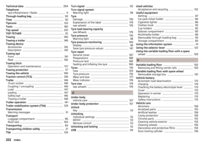 224
224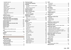 225
225 226
226 227
227 228
228 229
229 230
230 231
231