Page 129 of 232

Assist systems
General information
Introduction
WARNINGThe following general information regarding the use of assistance systems
must be observed.■
The assistance systems only serve to support and do not relieve the driv-
er of the responsibility for driving the vehicle.
■
The increased safety provision, as well as the increased occupant protec-
tion provided by the assistance systems must not tempt you to take risks -
risk of accident!
■
Adjust the speed and driving style to the current visibility, weather, road
and traffic conditions.
■
The assistance systems have physical and system-related limitations. For
this reason, the driver may experience some undesired or delayed system
responses in certain situations. You should therefore always be alert and
ready to intervene!
■
Only activate, deactivate or set the assistance systems so that you have
the car fully under control in every traffic situation - risk of accident!
Braking and stabilisation systems
Introduction
This chapter contains information on the following subjects:
Stability Control (ESC)
127
Anti-lock braking system (ABS)
127
Traction control (TCS)
128
Electronic Differential Lock (EDL)
128
Driver Steering Recommendation (DSR)
128
Brake Assist (HBA)
128
Hill Start Assist (HHC)
128
Trailer stabilization system (TSA)
129
This chapter describes the functions of the brake and stabilization systems.
The error display is in Chapter » page 32, Warning lights .
The brake and stabilization systems are automatically activated each time the
ignition is switched on, unless otherwise indicated.WARNINGThe general information relating to the use of assistance systems must be
observed » page 127, in section Introduction .
Stability Control (ESC)
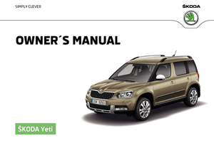
Fig. 140
Press the ESC system: Activat-
ing/deactivating TCS
Read and observe on page 127 first.
The ESC improves vehicle stability in dynamic driving situations, such as when
the vehicle starts to skid.
The ESC monitors whether the desired direction of the current vehicle motion
is occurring. In case of any deviation (e.g. over steer), the ESC automatically
brakes individual wheels to maintain the desired direction.
During an intervention of the system, the indicator light
flashes in the in-
strument cluster.
The ESC system cannot be deactivated. The
» Fig. 140 button can only be
used to deactivate the TCS » page 128.
The warning light
lights up in the instrument cluster when the ASR is deacti-
vated.
Anti-lock braking system (ABS)
Read and observe
on page 127 first.
ABS prevents the wheels locking when braking. Thus helping the driver to
maintain control of the vehicle.
127Assist systems
Page 130 of 232

The intervention of the ABS is noticeable from the pulsating movements of
the brake pedal which is accompanied by noises.
When the ABS system is active, do not brake periodically or reduce the pres- sure on the brake pedal.
Traction control (TCS)
Fig. 141
Button for the TCS system: TCS
disable / enable (vehicle without
ESC)
Read and observe on page 127 first.
TCS prevents the spinning of the wheels of the driven axle. TCS reduces the
drive power transmitted to the wheels in the case of slipping wheels. Thus, for
example, driving on road surfaces with low grip is made easier.
If your vehicle is fitted with the ESC system, the ASR is integrated into the ESC
system » page 127 .
During a TCS intervention, the indicator light flashes in the instrument clus-
ter.
The TCS should normally always be enabled. The system should be deactivated
only in the following situations, for example. ▶ When driving with snow chains.
▶ When driving in deep snow or on a very loose surface.
▶ When it is necessary to “rock” a car free when it has become stuck.
The ASR can be deactivated via the
» Fig. 141 symbol button.
The warning light lights up in the instrument cluster when the ASR is deacti-
vated.
Electronic Differential Lock (EDL)
Read and observe
on page 127 first.
EDL prevents the turning of the respective wheel of the driven axle. EDL
brakes the spinning wheel, if necessary, and transmits the driving force to the
other driving wheel. Driving becomes easier on road surfaces with different
traction under each wheel of the driven axle.
EDL switches off automatically to avoid excessive heat generation on the
brake of the wheel being braked. Once the brakes have cooled down, there is
an automatic re-activation of EDL.
Driver Steering Recommendation (DSR)
Read and observe
on page 127 first.
In critical situations, the DSR provides the driver with a steering recommenda-
tion in order to stabilise the vehicle. The DSR is activated, for example, on the
right and left vehicle side when braking sharply on different road surfaces.
Brake Assist (HBA)
Read and observe
on page 127 first.
The HBA increases the braking effect and helps to reduce the braking dis-
tance.
The HBA is activated by very quick operation of the brake pedal. In order to
achieve the shortest possible braking distance, the brake pedal must be ap-
plied firmly until the vehicle has come to a standstill.
The HBA function is automatically deactivated when the brake pedal is re-
leased.
Hill Start Assist (HHC)
Read and observe
on page 127 first.
When driving on slopes, HHC allows you to move your foot from the brake ped-
al to the accelerator pedal without having to use the handbrake.
The system holds the brake pressure produced by the activation of the brake pedal for approx. 2 seconds after the brake pedal is released.
128Driving
Page 131 of 232

Read and observe
on pag")
The HHC is active from a 5% slope if the driver's door is closed. HHC is only ev-
er active on slopes when in forward or reverse start off.
Trailer stabilization system (TSA)
Read and observe
on page 127 first.
The TSA helps the combination stable in situations where the trailer sways
and then the whole trailer combination.
TSA brakes the individual wheels of the towing vehicle in order to damp the
rocking motion of the entire vehicle combination.
The following conditions are required for the correct TSA function. The trailer was shipped from the factory or purchased from the ŠKODA
genuine accessories.
The trailer is electrically connected to the towing vehicle via the trailer
socket.
The TCS is activated.
The speed is higher than approx. 60 km/h.
Further information » page 141, Hitch and trailer .
OFF ROAD-mode
Introduction
This chapter contains information on the following subjects:
Operation
129
Hill Descent Assistant
130
TCSOFF ROAD
130
EDS OFF ROAD
130
ABS OFF ROAD
130
Start-Off Assistant
131
The OFF ROAD mode includes several features that help to overcome difficult
navigable routes when travelling on non-paved roads.
But even with OFF ROAD mode activated, your vehicle is never a true SUV.
WARNING■ The general information relating to the use of assistance systems must
be observed » page 127, in section Introduction .■
A lack of fuel can cause irregular engine running or cause the engine to
shut down. This would lead the OFF ROAD mode to lose its effectiveness -
risk of accident!
CAUTION
■ The OFF ROAD mode is not designed for the use on common roads.■All four wheels must be fitted with the same tyres approved by the manufac-
turer to ensure theOFF ROAD mode operates correctly.
Operation
Fig. 142
OFF ROAD button
Read and observe and on page 129 first.
We recommend that you activate the OFF ROAD mode for every trip on non- paved roads.
Activating
›
Press the symbol button
» Fig. 142 .
The symbol in the button comes on.
Deactivate
›
Press the symbol key
» Fig. 142 or turn the ignition off.
The symbol in the button is no longer illuminated.
129Assist systems
Page 132 of 232

So that an engagement of the OFF ROAD mode can take place, the following
conditions must be met.
The OFF ROAD mode is enabled.
The vehicle is moving at a speed of less than 30 km/h. The warning light
illuminates in the instrument cluster.
The following functions are integrated in the OFF ROAD mode.
▶ Downhill Drive Support » page 130.
▶ TCS OFF ROAD » page 130.
▶ EDL OFF ROAD » page 130.
▶ ABS OFF ROAD » page 130.
▶ Start-Off Assistant » page 131.
Note
If the engine stalls while driving and is started again within 30 seconds, then
OFF ROAD mode will be automatically activated.
Hill Descent Assistant
Read and observe
and on page 129 first.
The hill descent assistant (hereinafter referred to as assistant), with its auto-
matic braking action on all wheels, ensures a constant speed is maintained on
a steep slope when driving forwards and reversing.
During an intervention of the Assistants, the warning light flashes in the in-
strument cluster.
The assistant is automatically engaged under the following conditions. The engine is running.
For vehicles with Manual transmission the shift lever is in the neutral po-
sition and or the 1st, 2nd, 3rd gear, or reverse gear is engaged.
On vehicles with an automatic transmission , the selector lever is in the R,
N, D, S position or in the Tiptronic position.
The downhill gradient is at least 10 % (when driving over sleepers, the lim-
it can briefly drop to 8 %).
Neither the accelerator nor the brake pedal is operated.
Driving speed
Initiate the downhill decent at a reasonable speed up to 30 km / h the hill de-
scent assist maintains this speed when driving downhill constant.
The assistant can maintain constant speed of about 2 - 30 km / h.
If a forwards or reverse gear is engaged for vehicles with Manual transmis-
sion , the speed must be high enough to avoid stalling the engine.
By pressing the accelerator or brake pedal, the speed can be increased or re-
duced. This is true even if the shift lever is in the neutral position and the se-
lector lever in the N position. The engagement of the assistant is resumed af-
ter the pedal is released.WARNINGFor the correct operation of the assistant the road surface must be suffi-
ciently adherent. The assistant cannot properly fulfil its function on slushy
soil due to physical reasons (e.g. ice or mud). - there is a risk of an accident!
Note
During an active intervention of the assistant, the brake lights do not light up.
TCSOFF ROAD
Read and observe
and on page 129 first.
The ASR OFF ROAD makes starting and driving on an unpaved surface easier
as it partially allows wheel-spin.
Note
When disabled, the TCS » Fig. 140 on page 127 OFF ROAD mode works without
the support of the TCS OFF ROAD.
EDS OFF ROAD
Read and observe
and on page 129 first.
The EDS supports OFF ROAD vehicle traction when driving on a surface withdifferent grip under the drive wheels or when driving over bumps.
A spinning wheel or wheels are braked earlier and with more force than with
the intervention of the standard EDS system.
ABS OFF ROAD
Read and observe
and on page 129 first.
The ABS OFF ROAD supports the driver when braking on an unpaved surface
such as gravel, snow, etc.
130Driving
Page 133 of 232

The system generated by a controlled locking of the wheels braked wheel be-
fore a “wedge” of piled material, which shortens the braking distance.
The system is only available, if the front wheels are in the straight-ahead posi-
tion.
The system operates at speeds of up to 50 km/h.
Start-Off Assistant 1)
Read and observe
and on page 129 first.
The Start-Off assistant assists the driver when setting off, such as on a steep
slope or on a slippery surface. When the driver presses the accelerator, the
maximum engine speed is electronically limited so that a gentle approach is
possible.
Parking assistance (ParkPilot)
Introduction
This chapter contains information on the following subjects:
Function
131
Display in the Infotainment display
132
Activation/deactivation
133
The parking aid (hereinafter referred to as system) draws attention via acous- tic signals or the Infotainment display when manoeuvring around obstacles in
the vicinity of the vehicle.
WARNING■ The general information relating to the use of assistance systems must
be observed » page 127, in section Introduction .■
Moving persons or objects may not be recognized by the system sensors.
■
Under certain circumstances, surfaces of certain objects and types of
clothing cannot reflect the system signals. For this reason, such people or
objects may not be recognised by the system sensors.
WARNING (Continued)■ External noise sources may affect the signals of the system sensors. Un-
der adverse conditions, this may cause objects or people not to be recog-
nised by the system.■
Before reversing, you should make sure that there are no small obstacles,
such as rocks, thin posts, trailer drawbars etc. in front or behind your vehi-
cle. Such obstacles may not be recognised by the system sensors.
CAUTION
■ Keep the system sensors » Fig. 143 on page 131 clean, snow-and ice-free
and do not cover with any objects of any kind, otherwise the system function-
ing may be impaired.■
Under adverse weather conditions (heavy rain, water vapour, very low or
high temperatures, etc.), the system function may be limited - “incorrect recog-
nition of obstacle”.
■
Accessories additionally installed on the vehicle rear, such as bicycle carriers,
can impair the system function.
Function
Fig. 143
Installation position of the sensors on the left side of the vehi-
cle: front/rear
1)
Only for vehicles with a petrol engine and manual transmission.
131Assist systems
Page 134 of 232

Fig. 144
Sampled areas and range of the
sensors
Read and observe and on page 131 first.
The system uses ultrasound waves to calculate the distance between the
bumper and an obstacle. The ultrasonic sensors are, depending on vehicle
equipment, located in the back or in the front bumper » Fig. 143.
Depending on the equipment, the following system versions can exist
» Fig. 144 .
▶ Version 1: warns of obstacles in the areas
C
,
D
.
▶ Version 2: warns of obstacles in the regions
A
,
B
,
C
,
D
.
▶ Version 3: warns of obstacles in the regions
A
,
B
,
C
,
D
,
E
.
Approximate range of sensors (in cm)
Area » Fig. 144Version 1
(4 sensors)Version 2
(8 sensors)Version 3
(12 sensors)A-120120B-6060C160160160D606060E--60
Audible signals
The interval between the acoustic signals becomes shorter as the clearance is
reduced. A continuous tone sounds from a distance of approx. 30 cm - danger
area. From this moment on do not continue driving!
Towing a trailer
When towing, or when another accessory is connected to the trailer socket on-
ly the areas
A
and
B
» Fig. 144 are active in the system.
Note■
If with Version 3 vehicles not all fields around the vehicle are active after ac-
tivation the vehicle should be moved forwards or backwards.■
The signal tones for front obstacle recognition are factory-set to be higher
than for rear obstacle recognition.
■
The sound of the park-assist can be adjusted via the MAXI DOT display in the
Assistants
menu option » page 47.
Display in the Infotainment display
Fig. 145
Display
Read and observe and on page 131 first.
Function keys and obstacle warning » Fig. 145
Change to rear-view camera display .
Switching off park assistant display. Switching audible parking signals on/off.
Message:
Look! Safe to move?
An area without detected obstacles is shown as a transparent segment.
An obstacle which is currently outside of the collision area is shown by the
yellow segment.
An obstacle in the collision zone is shown as an orange-coloured segment.
Stop driving in the direction of an obstacle!
ABC132Driving
Page 135 of 232

Read and observe and on page 131 first.
Activation
The activation of the system is initiated when the reverse gear is engaged, or
vehicles w")
Activation/deactivationFig. 146
System key (option 2, 3)
Read and observe and on page 131 first.
Activation
The activation of the system is initiated when the reverse gear is engaged, or
vehicles with the Variant 2 and 3 , also by pressing the symbol key
» Fig. 146 .
This is confirmed by a short acoustic signal ( the symbol in the button is lit).
Deactivation
On vehicles with Version 1, the system can be deactivated by moving out of re-
verse gear.
For vehicles with the Version 2 and 3 the system is automatically deactivated
by pressing the symbol key or at a speed over 15 km / h (the symbol
in the
button goes out).
Fault display
If a warning signal sounds for about 3 seconds after activating the system and
there is no obstacle close to your car, this indicates a system fault. The fault is
also indicated by the symbol flashing in the button. Seek help from a spe-
cialist garage.
Note
The system can only be activated with the symbol key at a speed of below
15 km / hr.Rear View Camera
Introduction
This chapter contains information on the following subjects:
Operation
134
Guidelines and function keys
134
The rear view camera (hereinafter referred to as system) helps the driver when
parking and manoeuvring by displaying the area behind the vehicle in the Info-
tainment display (hereinafter referred to as display).
WARNING■ The general information relating to the use of assistance systems must
be observed » page 127, in section Introduction .■
Make sure that the camera lens is not dirty or covered, otherwise the sys-
tem function can be significantly impaired. For information on cleaning
» page 156 , Camera lens
CAUTION
■
The camera lens distorts and enlarges the field of view of the difference in
eye sight. The display is therefore only of limited use for estimating distances
to following vehicles.■
Some items, such as thin columns, chain link fences or lattice may not be
represented adequately in terms of display resolution.
■
It is only a two-dimensional display. Therefore, protruding objects or roadway
depressions, for example, may not be recognised due to lack of space depth.
■
In a crash or damage the vehicle's rear camera can possibly deviate from the
correct position. If this is the case, have the sensor checked by a specialist ga-
rage.
133Assist systems
Page 136 of 232

OperationFig. 147
Position of the camera / monitored area
Read and observe
and on page 133 first.
The camera for capturing the area behind the vehicle is in the grip of the boot
lid » Fig. 147 .
Supervised area » Fig. 147
Detection range of the camera.
Area outside the detection range of the camera.
The area behind the vehicle is displayed when the following conditions are
met.
The ignition is switched on.
Reverse gear is engaged. 1)
The luggage compartment lid is completely closed.
The vehicle is not travelling at more than about 15 km/h.
Note
■ The display can be interrupted by pressing the symbol key » Fig. 144 on
page 132 .■
After disengaging the reverse gear, automatic display of the parking aid is
carried out (variant 2, 3) » page 131.
ABGuidelines and function keysFig. 148
Infotainment display: Orientation lines / function keys
Read and observe
and on page 133 first.
Orientation lines are shown along with the monitored area behind the vehicle
in the display.
Distance of the orientation lines behind the vehicle » Fig. 148
The distance is about 40 cm (safety distance limit).
The distance is approximately 100 cm.
The distance is approximately 200 cm.
The distance between the side lines corresponds approximately to the vehicle width including mirrors.
Function keys » Fig. 148
Turns off the display of the area behind the vehicle.
Display settings - brightness, contrast, colour. Switching audible parking signals on/off.
Switching reduced park assistance display on / off.
Change to park assistance display.
CAUTION
The objects shown in the display can be closer or even further away than they
appear. This is especially the case in the following situations.■
Protruding objects, such as a hitch, the rear of a truck and the like.
■
When driving from a horizontal surface into a slope or a depression.
■
When driving from a slope or a depression onto a horizontal surface.
ABC
1)
The area behind the vehicle can be displayed for a few seconds more after disengaging the reverse gear.
134Driving
 1
1 2
2 3
3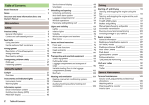 4
4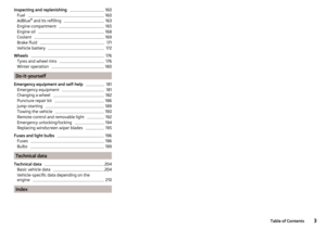 5
5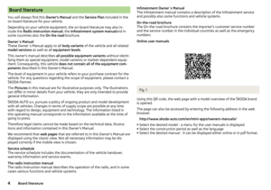 6
6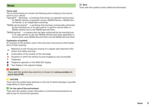 7
7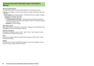 8
8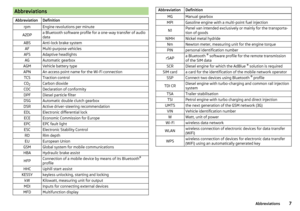 9
9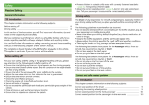 10
10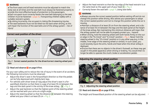 11
11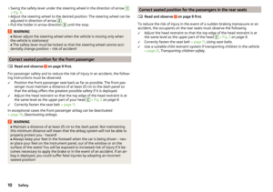 12
12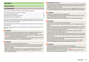 13
13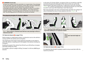 14
14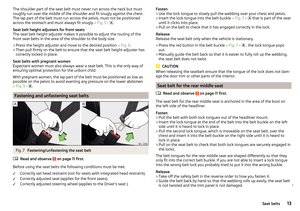 15
15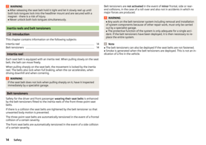 16
16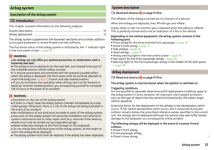 17
17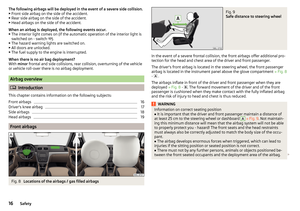 18
18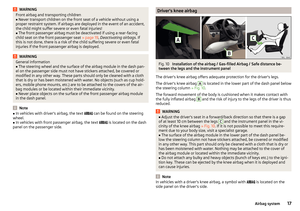 19
19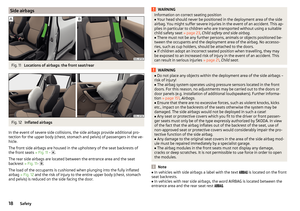 20
20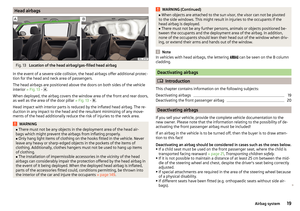 21
21 22
22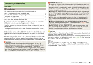 23
23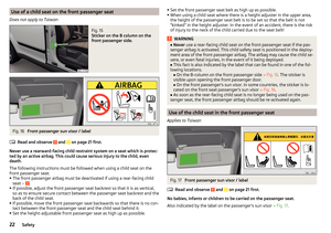 24
24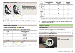 25
25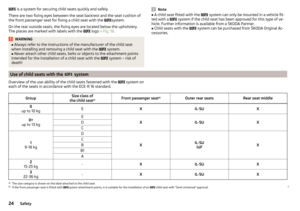 26
26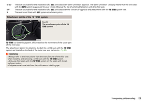 27
27 28
28 29
29 30
30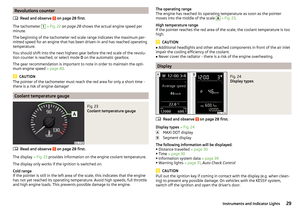 31
31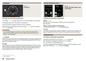 32
32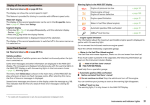 33
33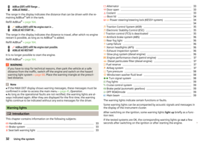 34
34 35
35 36
36 37
37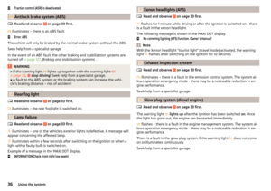 38
38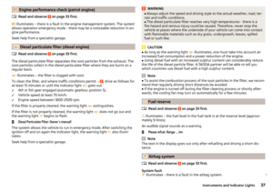 39
39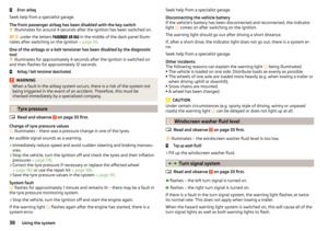 40
40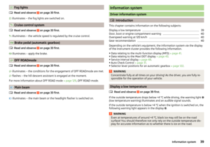 41
41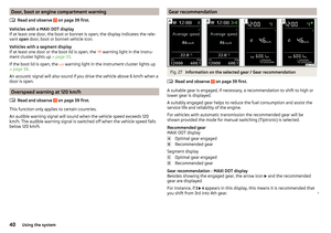 42
42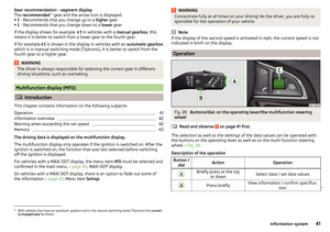 43
43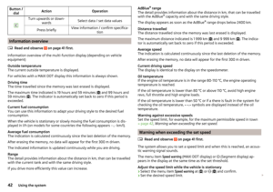 44
44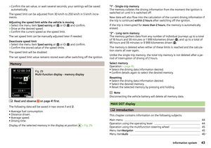 45
45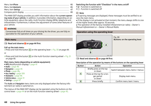 46
46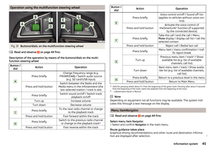 47
47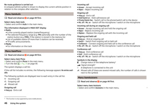 48
48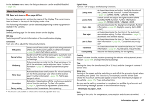 49
49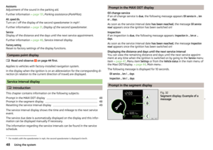 50
50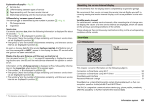 51
51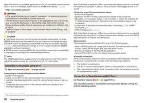 52
52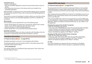 53
53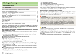 54
54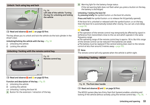 55
55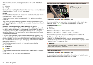 56
56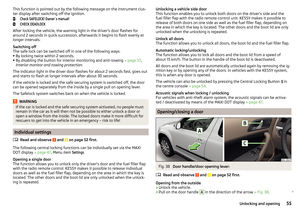 57
57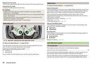 58
58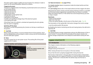 59
59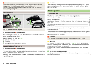 60
60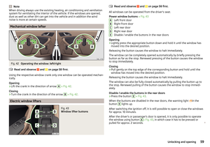 61
61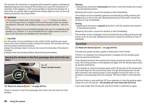 62
62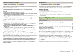 63
63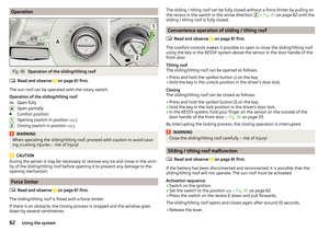 64
64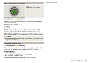 65
65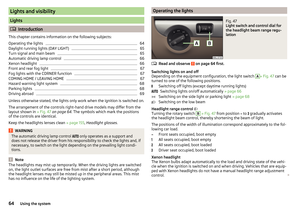 66
66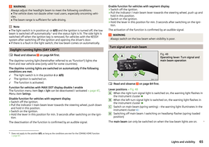 67
67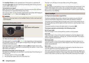 68
68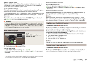 69
69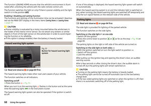 70
70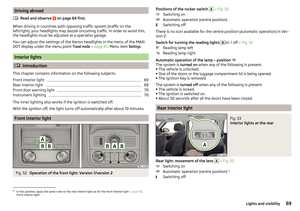 71
71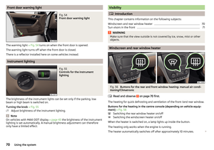 72
72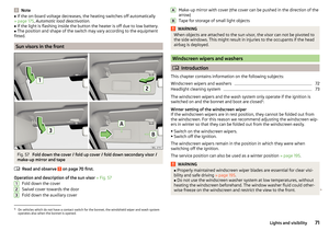 73
73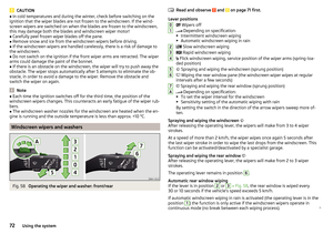 74
74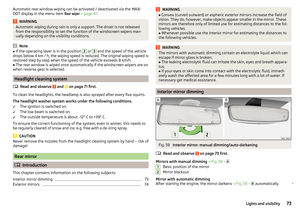 75
75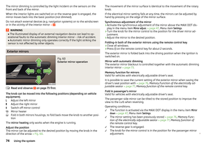 76
76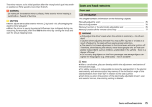 77
77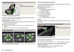 78
78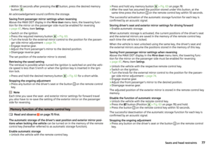 79
79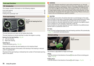 80
80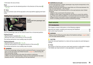 81
81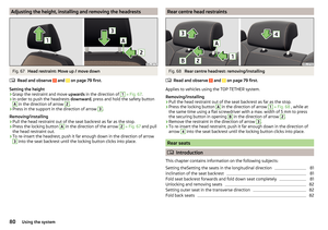 82
82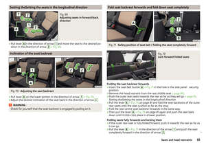 83
83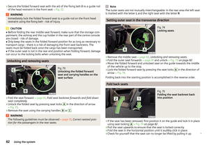 84
84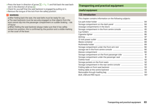 85
85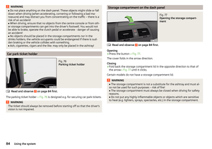 86
86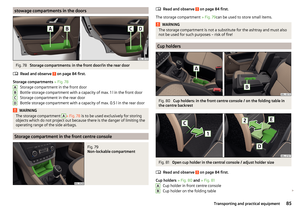 87
87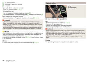 88
88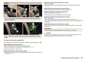 89
89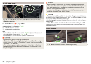 90
90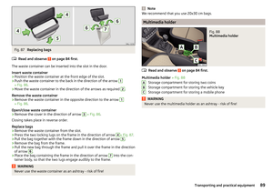 91
91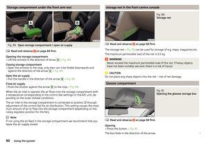 92
92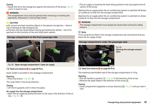 93
93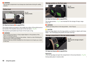 94
94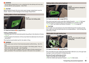 95
95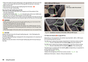 96
96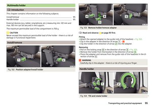 97
97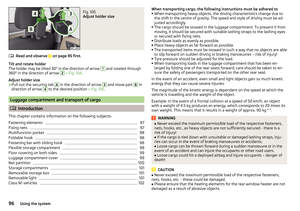 98
98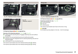 99
99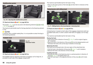 100
100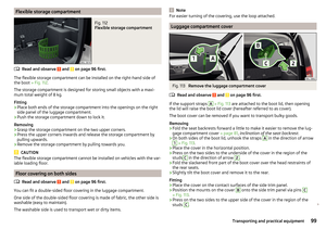 101
101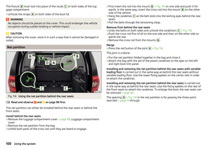 102
102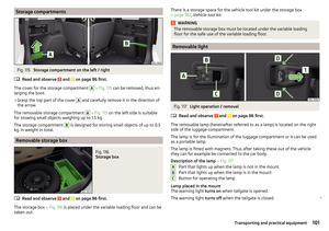 103
103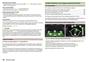 104
104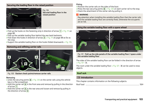 105
105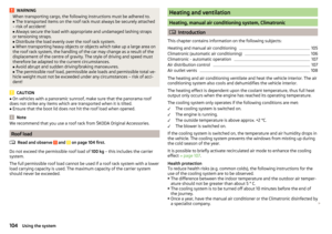 106
106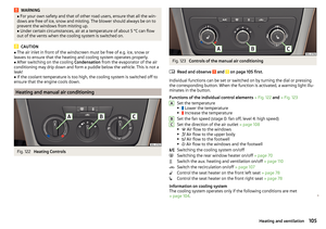 107
107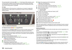 108
108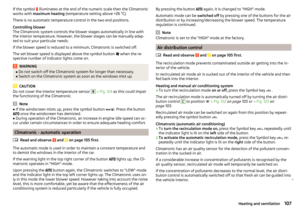 109
109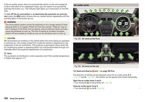 110
110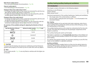 111
111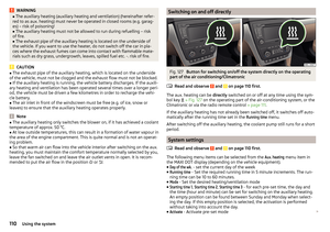 112
112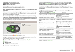 113
113 114
114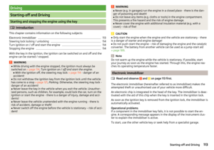 115
115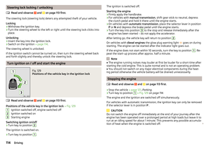 116
116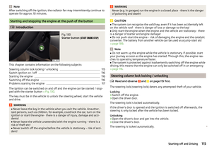 117
117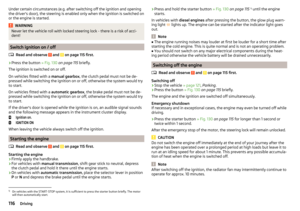 118
118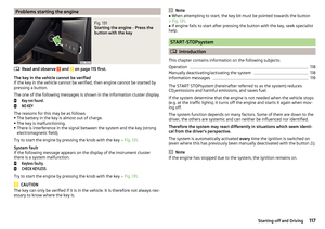 119
119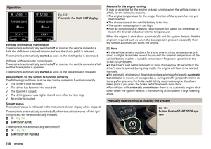 120
120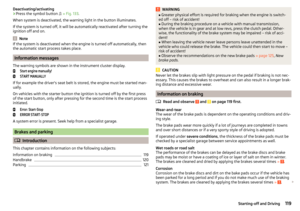 121
121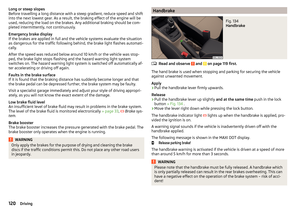 122
122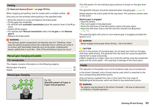 123
123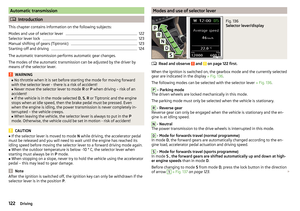 124
124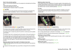 125
125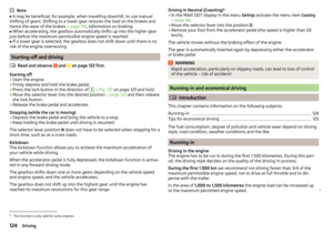 126
126 127
127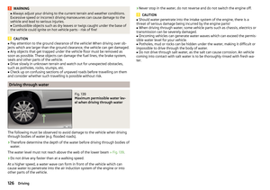 128
128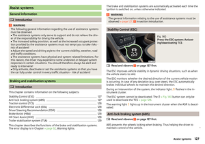 129
129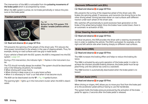 130
130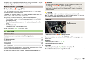 131
131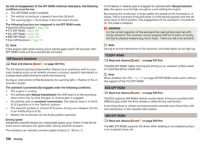 132
132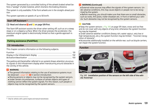 133
133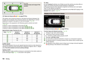 134
134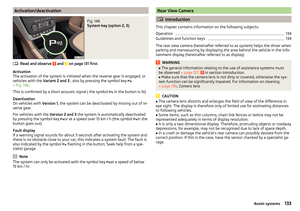 135
135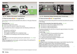 136
136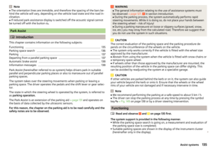 137
137 138
138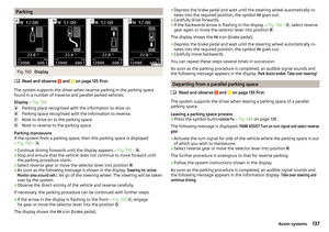 139
139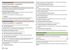 140
140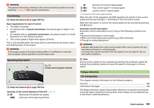 141
141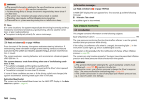 142
142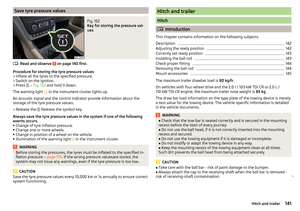 143
143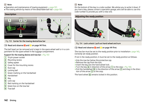 144
144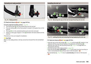 145
145 146
146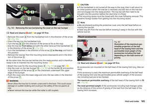 147
147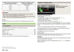 148
148 149
149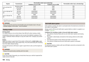 150
150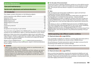 151
151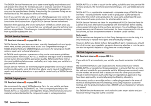 152
152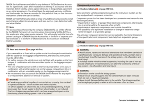 153
153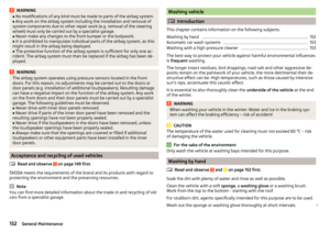 154
154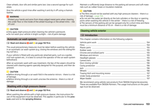 155
155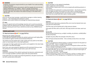 156
156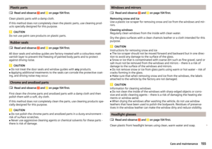 157
157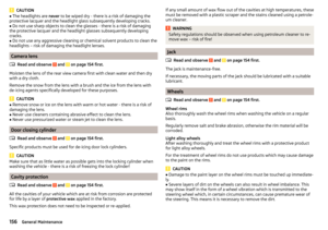 158
158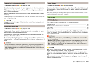 159
159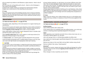 160
160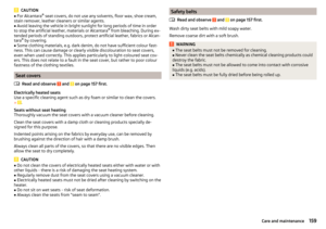 161
161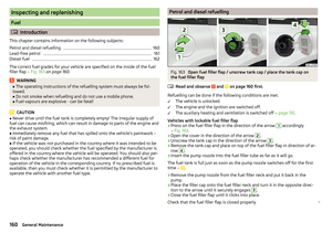 162
162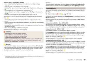 163
163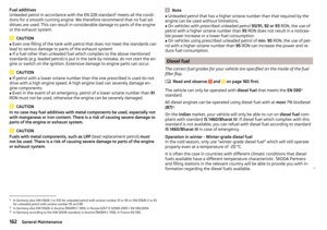 164
164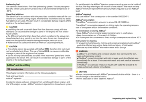 165
165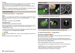 166
166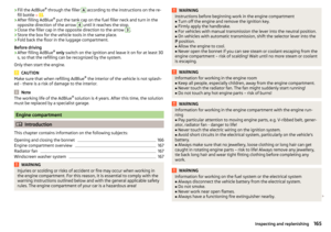 167
167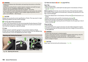 168
168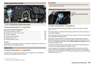 169
169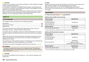 170
170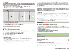 171
171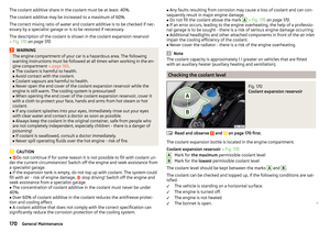 172
172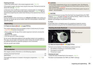 173
173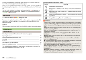 174
174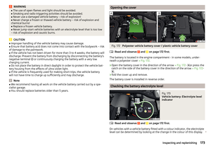 175
175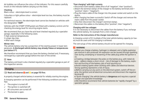 176
176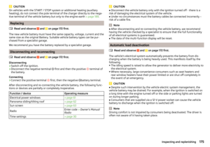 177
177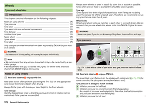 178
178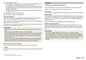 179
179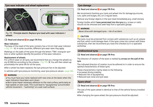 180
180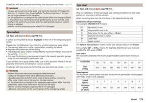 181
181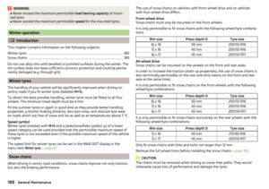 182
182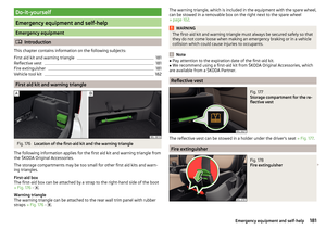 183
183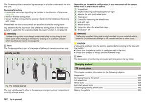 184
184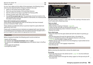 185
185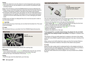 186
186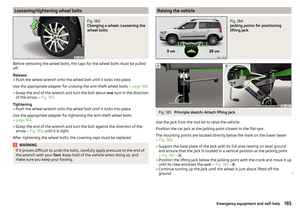 187
187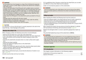 188
188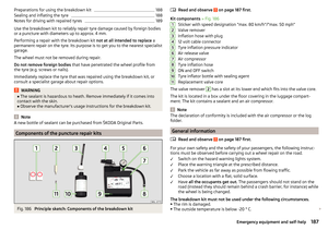 189
189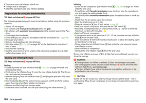 190
190 191
191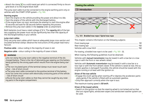 192
192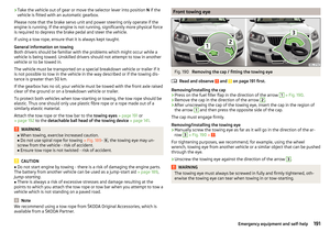 193
193 194
194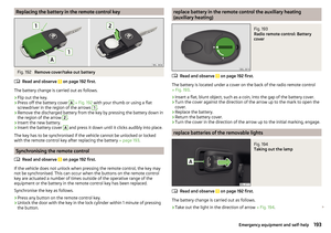 195
195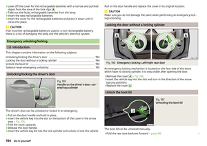 196
196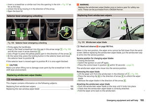 197
197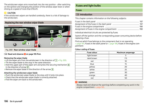 198
198 199
199 200
200 201
201 202
202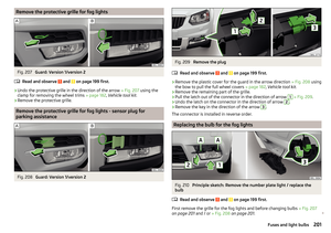 203
203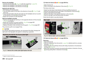 204
204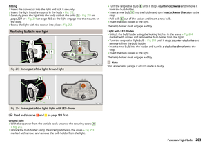 205
205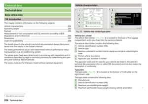 206
206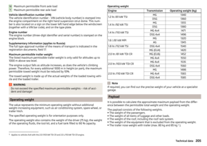 207
207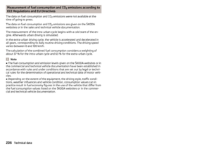 208
208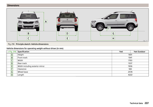 209
209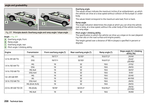 210
210 211
211 212
212 213
213 214
214 215
215 216
216 217
217 218
218 219
219 220
220 221
221 222
222 223
223 224
224 225
225 226
226 227
227 228
228 229
229 230
230 231
231