Page 105 of 232

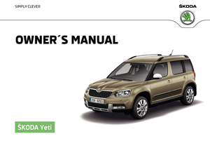
Securing the loading floor in the raised positionFig. 119
Secured loading floor in the
raised position
›
Fold up the hooks on the fastening strip in direction of arrow
1
» Fig. 111 on
page 98 .
›
Fold up the variable loading floor behind the rear back backrests.
›
Fold down the hooks in direction of arrow
3
» Fig. 111 on page 98 as far as
the stop.
›
Support the variable loading floor on the hooks folded downwards » Fig. 119.
Removing and refitting carrier rails
Fig. 120
Slacken check points/remove carrier rails
Removing
›
Undo the securing points
B
» Fig. 120 on the carrier rails using the vehicle
key or a flat screwdriver.
›
Hold the carrier rail
A
in the front area and remove by pulling in the direction
of arrow
1
.
›
Hold the carrier rail
A
in the rear area and loosen and remove by pulling in
the direction of arrow
2
.
Fitting›Position the carrier rails on the sides of the boot.›
Press the two securing points
B
» Fig. 120 on each carrier rail to the stop.
›
Check the attachment of the carrier rails by pulling it.
WARNINGPay attention when installing the variable loading floor that the carrier rails
and the variable loading floor are correctly fixed, otherwise the occupants
are at risk.
Using the variable loading floor with a spare wheel
Fig. 121
Fold up the side panels of the variable loading floor / space under
the variable loading floor
The sides of the variable loading floor can be folded in the direction of arrow
» Fig. 121 -
.
The room under the variable loading floor » Fig. 121 -
can be used to stow
objects.
Roof rack
Introduction
This chapter contains information on the following subjects:
Roof load
104
103Transporting and practical equipment
Page 106 of 232

WARNINGWhen transporting cargo, the following instructions must be adhered to.■The transported items on the roof rack must always be securely attached
– risk of accident!■
Always secure the load with appropriate and undamaged lashing straps
or tensioning straps.
■
Distribute the load evenly over the roof rack system.
■
When transporting heavy objects or objects which take up a large area on
the roof rack system, the handling of the car may change as a result of the
displacement of the centre of gravity. The style of driving and speed must
therefore be adapted to the current circumstances.
■
Avoid abrupt and sudden driving/braking manoeuvres.
■
The permissible roof load, permissible axle loads and permissible total ve-
hicle weight must not be exceeded under any circumstances – risk of acci-
dent!
CAUTION
■ On vehicles with a panoramic sunroof, make sure that the panorama roof
does not strike any items which are transported when it is tilted.■
Ensure that the boot lid does not hit the roof load when opened.
Note
We recommend that you use a roof rack from ŠKODA Original Accessories.
Roof load
Read and observe
and on page 104 first.
Do not exceed the permissible roof load of 100 kg – this includes the carrier
system.
The full permissible roof load cannot be used if a roof rack system with a lower
load carrying capacity is used. The maximum capacity of the carrier system
should never be exceeded.
Heating and ventilation
Heating, manual air conditioning system, Climatronic
Introduction
This chapter contains information on the following subjects:
Heating and manual air conditioning
105
Climatronic (automatic air conditioning)
106
Climatronic - automatic operation
107
Air distribution control
107
Air outlet vents
108
The heating and air conditioning ventilate and heat the vehicle interior. The air
conditioning system also cools and dehumidifies the vehicle interior.
The heating effect is dependent upon the coolant temperature, thus full heat
output only occurs when the engine has reached its operating temperature.
The cooling system only operates if the following conditions are met: The cooling system is switched on.
The engine is running.
The outside temperature is above approx. +2 °C.
The blower is switched on.
If the cooling system is switched on, the temperature and air humidity drops in the vehicle. The cooling system prevents the windows from misting up during
the cold season of the year.
It is possible to briefly activate recirculated air mode to enhance the cooling
effect » page 107 .
Health protection
To reduce health risks (e.g. common colds), the following instructions for the
use of the cooling system are to be observed. ▶ The difference between the indoor temperature and the outdoor air temper-
ature should not be greater than about 5 ° C.
▶ The cooling system is to be turned off about 10 minutes before the end of
the journey.
▶ Once a year, have the manual air conditioner or the Climatronic disinfected by
a specialist company.
104Using the system
Page 107 of 232

WARNING■For your own safety and that of other road users, ensure that all the win-
dows are free of ice, snow and misting. The blower should always be on to
prevent the windows from misting up.■
Under certain circumstances, air at a temperature of about 5 °C can flow
out of the vents when the cooling system is switched on.
CAUTION
■ The air inlet in front of the windscreen must be free of e.g. ice, snow or
leaves to ensure that the heating and cooling system operates properly.■
After switching on the cooling Condensation from the evaporator of the air
conditioning may drip down and form a puddle below the vehicle. This is not a
leak!
■
If the coolant temperature is too high, the cooling system is switched off to
ensure that the engine cools down.
Heating and manual air conditioning
Fig. 122
Heating Controls
Fig. 123
Controls of the manual air conditioning
Read and observe
and on page 105 first.
Individual functions can be set or switched on by turning the dial or pressing the corresponding button. When the function is activated, a warning light illu-
minates in the button.
Functions of the individual control elements » Fig. 122 and » Fig. 123
Set the temperature
▶ Lower the temperature
▶ Increase the temperature
Set the fan speed (stage 0: fan off, level 4: high speed)
Set the direction of the air outlet » page 108
▶ Air flow to the windows
▶ Air flow to the upper body
▶ Air flow to the footwell
▶ Air flow to the windows and the footwell
Switching the cooling system on/off
Switching the rear window heater on/off » page 70
Switch the aux. heating and ventilation on/off » page 110
Switch the recirculation on/off » page 107
Control the seat heater on the front left seat » page 78
Control the seat heater on the front right seat » page 78
Information on cooling system
The cooling system operates only if the following conditions are met
» page 104 .
ABC105Heating and ventilation
Page 108 of 232

The warning light in the button » Fig. 123 illuminates after activation, even
if not all of the conditions for the function of the cooling system have been
met. By lighting up of the indicator light in the button, the operational readi-
ness of the cooling system is signalled.
Note
During operation of the manual air conditioning, an increase in engine idle
speed may occur under certain circumstances in order to ensure sufficient
heating comfort.
Climatronic (automatic air conditioning)
Fig. 124
Controls the Climatronic
Read and observe
and on page 105 first.
The Climatronic in automatic mode ensures the best-possible setting of the
temperature of the out-flowing air, the blower stage and air distribution.
Individual functions can be set or switched on by turning the dial or pressing
the corresponding button. When the function is activated, a warning light illu-
minates in the button.
Functions of the individual controls » Fig. 124
Adjust the temperature for the left side or for both sides
▶ Lower the temperature
▶ Increase the temperature
Interior temperature sensor
Depending on equipment fitted:
▶ Switching the windscreen heater on/off
» page 70
▶ Switch the aux. heating and ventilation on/off
» page 110
ABCAdjust the temperature for the right side
▶ Lower the temperature
▶ Increase the temperature
Control the seat heater on the front left seat » page 78
Control the seat heater on the front right seat » page 78
Adjust the blower speed ▶ + Increase speed
▶ - Reduce speed
Switch the intensive windscreen heater on/off
Air flow to the windows
Air flow to the upper body
Air flow in the footwell Switch the automatic recirculation on/off » page 107
Switch the rear window heater on/off » page 70
Switching automatic mode on
Switch the Climatronic system off »
Switching the cooling system on/off
Switch the temperature setting in Dual mode on/off
After the cooling system is switched off, only the ventilation function remains
active whereby the minimum temperature that can be reached is the outside
temperature.
Setting temperature
The interior temperature for the left and right side can be set separately or to-
gether.
The temperature for both sides, is set by turning the knob
A
» Fig. 124 (the
indicator light in the button is not illuminated).
The temperature for the right side is adjusted by turning the knob
D
(the in-
dicator light in the button is lit).
The temperature for the left side is adjusted by turning the knob
A
(the indi-
cator light in the button is lit).
The temperature can be set between +18 °C and +26 °C. The temperature is
regulated automatically within this range.
If the symbol illuminates at the beginning of the numeric scale then the Cli-
matronic works with maximum cooling (temperature setting below +18 °C).
D106Using the system
Page 109 of 232
.
There is no automatic temperature control in the tw")
If the symbol illuminates at the end of the numeric scale then the Climatronic
works with maximum heating (temperature setting above +26 °C).
There is no automatic temperature control in the two end positions.
Controlling blower
The Climatronic system controls the blower stages automatically in line with the interior temperature. However, the blower stages can be manually adap-
ted to suit your particular needs.
If the blower speed is reduced to a minimum, Climatronic is switched off.
The set blower speed is displayed above the symbol button
when the re-
spective number of indicator lights come on.WARNING■ Do not switch off the Climatronic system for longer than necessary.■Switch on the Climatronic system as soon as the windows mist up.
CAUTION
Do not cover the interior temperature sensor B » Fig. 124 as this could impair
the functioning of the Climatronic.
Note
■ If the windscreen mists up, press the symbol button . Press the button
once the windscreen has demisted.■
During operation of the Climatronic, an increase in engine idle speed can oc-
cur under certain circumstances in order to ensure adequate heating comfort.
Climatronic - automatic operation
Read and observe
and on page 105 first.
The automatic mode is used in order to maintain a constant temperature andto demist the windows in the interior of the car.
If the warning light in the top right corner of the button lights up, the Cli-
matronic operates in “HIGH”-mode.
Upon pressing the button again, the Climatronic switches to “LOW”-mode
and the indicator light in the top left corner lights up. The Climatronic uses on-
ly in this mode the lower blower speed. However taking into account the noise
level, this is more comfortable, yet be aware that the effectiveness of the air
conditioning system is reduced particularly if the vehicle is fully occupied.
By pressing the button again, it is changed to “HIGH”-mode.
Automatic mode can be switched off by pressing one of the buttons for the air
distribution or by increasing/decreasing the blower speed. The temperature
regulation is continued.
Note
Climatronic is set to the “HIGH” mode at the factory.
Air distribution control
Read and observe
and on page 105 first.
The recirculation mode prevents contaminated outside air getting into the in-
terior of the vehicle.
In recirculated air mode air is sucked out of the interior of the vehicle and then
fed back into the interior.
Heating and manual air conditioning system
›
To turn the recirculation mode on or off, press the Symbol key
.
The air recirculation mode is automatically turned off by turning the air distri-
bution control
C
to position
» Fig. 122 on page 105 or » Fig. 123 on
page 105 .
Recirculated air mode can be switched on again from this position by repeat-
edly pressing the symbol button .
Climatronic (automatic air conditioning)
›
To turn the recirculation mode on, press the Symbol key
repeatedly until
the indicator light is lit on the left side of the button.
›
To activate the automatic recirculation mode, press the Symbol key
re-
peatedly until the indicator light is lit on the right side of the button.
Climatronic has an air quality sensor for the detection of the pollutant concen-
tration in the sucked-in air.
If a considerable increase in concentration of pollutants is recognised by the
air quality sensor, recirculated air mode will temporarily be switched on.
If the concentration of pollutants decreases to the normal level, the air distri-
bution control is automatically switched off so that fresh air can be guided into
the vehicle interior.
107Heating and ventilation
Page 110 of 232

If the air quality sensor does not automatically switch on the recirculated air
mode in the event of an unpleasant odour, you can switch it on yourself by
pressing the button . The indicator light lights up in the button on the left
side.
To turn off the air recirculation or to deactivate the automatic air recircula-
tion , press the
button of press the symbol button repeatedly until the
warning lights in the button go out.WARNINGThe recirculation system cannot be switched on for a longer period of time,
because there is no supply of fresh air from the outside. “Stale air” may re-
sult in fatigue in the driver and occupants, reduce attention levels and also
cause the windows to mist up. The risk of having an accident increases.
Switch off recirculated air mode as soon as the windows start to mist up.
CAUTION
We recommend not smoking in the vehicle when the recirculating air operation
is switched on. The smoke sucked from inside the vehicle is deposited on the
evaporator of the air conditioner. This produces a permanent odour when the
air conditioning system is operating which can only be eliminated through con-
siderable effort and expense (replacement of compressor).
Note
The automatic air distribution control operates only if the outside temperature
is higher than approx. 2 °C.Air outlet ventsFig. 125
Air vents at the front
Fig. 126
Air vents at the rear
Read and observe
and on page 105 first.
The direction of airflow can be adjusted using the air outlet vents 3, 4
» Fig. 125 and 6 » Fig. 126 – the outlets can be opened and closed individually.
Open the air outlet vents 3 and 4
›
Turn the knob
B
to the position
» Fig. 125 .
Close air outlet vents 3 and 4
›
Turn the knob
B
to the 0 » Fig. 125 .
108Using the system
Page 111 of 232

Open the air outlet vents 6›Turn the knob C between the end positions » Fig. 126.
Close air outlet vents 6›
Turn the knob
C
to the end position » Fig. 126.
Change air flow of air outlet vents 3 and 4
›
To change the height of the air flow, swivel the horizontal fins with the mov-
able adjuster elements
A
upward or downward » Fig. 125.
›
To adjust the lateral direction of the air flow, turn the vertical fins with the
movable adjuster element
A
to the left or to the right.
Change air flow of air outlet vents 6
›
To change the height of the air flow, swivel the horizontal fins with the verti-
cal adjuster elements
C
upward or downward » Fig. 126.
›
To adjust the lateral direction of the air flow, turn the vertical fins with the
horizontal movable adjuster element
D
to the left or to the right.
An overview of the available settings for adjusting the direction of the air
outlet
Set the direction of the air outletActive air outlet nozzles » Fig. 125 and
» Fig. 126 1. 2 . 41. 2 . 4 . 5 . 7 3. 4 . 64 . 5 . 7
CAUTION
To ensure that the heating, the manual air conditioning and the Climatronic
systems work properly, do not block up the air outlet vents with any objects.
Note
The air outlet vents 6 » Fig. 126 are only fitted on vehicles with the higher cen-
tre console.Auxiliary heating (auxiliary heating and ventilation)
Introduction
This chapter contains information on the following subjects:
Switching on and off directly
110
System settings
110
Radio remote control
111
Functional requirements of the auxiliary heating (aux. heating and ventilation) The charge state of the vehicle battery is sufficient.
The fuel supply is adequate (the warning light is not illuminated in the
instrument cluster).
Aux. heating
The auxiliary heating can be used when both when stationary, when the en-
gine is switched off, to preheat the vehicle and also while driving (e.g. during
the heating phase of the engine).
The auxiliary heating warms up the coolant by combusting fuel from the vehi-
cle tank. This heats the air flowing into the passenger compartment (if the
blower is turned on).
The auxiliary heating also warms up the engine.
The heater is switched on or off automatically depending on the ambient con-
ditions to give the best possible conditions for the engine running and the in-
terior heating.
For vehicles with gasoline engines, the automatic switching on and off of the
heater can be disabled in a specialist workshop.
Auxiliary ventilation
The auxiliary ventilation enables fresh air to flow into the vehicle interior by
switching off the engine, whereby the interior temperature is effectively de-
creased (e.g. with the vehicle parked in the sun).
109Heating and ventilation
Page 112 of 232
 (hereinafter refer-
red to as aux. heating) must never be operated in closed rooms (e.g. garag-
es) – risk of poisoning!■
The au")
WARNING■The auxiliary heating (auxiliary heating and ventilation) (hereinafter refer-
red to as aux. heating) must never be operated in closed rooms (e.g. garag-
es) – risk of poisoning!■
The auxiliary heating must not be allowed to run during refuelling – risk
of fire.
■
The exhaust pipe of the auxiliary heating is located on the underside of
the vehicle. If you want to use the heater, do not switch off the car in pla-
ces where the exhaust fumes can come into contact with flammable mate-
rials such as dry grass, undergrowth, leaves, spilled fuel etc. -. risk of fire.
CAUTION
■ The exhaust pipe of the auxiliary heating, which is located on the underside
of the vehicle, must not be clogged and the exhaust flow must not be blocked.■
If the auxiliary heating is running, the vehicle battery discharges. If the auxili-
ary heating and ventilation has been operated several times over a longer peri-
od, the vehicle must be driven a few kilometres in order to recharge the vehi-
cle battery.
■
The air inlet in front of the windscreen must be free (e.g. of ice, snow or
leaves) to ensure that the auxiliary heating operates properly.
Note
■ The auxiliary heating only switches the blower on, if it has achieved a coolant
temperature of approx. 50 °C.■
At low outside temperatures, this can result in a formation of water vapour in
the area of the engine compartment. This is quite normal and is not an operat-
ing problem.
■
So that warm air can flow into the vehicle interior after switching on the aux.
heating, you must maintain the comfort temperature normally selected by you,
leave the fan switched on and leave the air outlet vents in open. It is recom-
mended to put the air flow in the position
or
.
Switching on and off directlyFig. 127
Button for switching on/off the system directly on the operating
part of the air conditioning/Climatronic
Read and observe
and on page 110 first.
The aux. heating can be directly switched on or off at any time using the sym-
bol key
» Fig. 127 on the operating part of the air-conditioning system, or the
Climatronic or via the radio remote control » page 111.
If the auxiliary heating has not already been switched off, it switches off auto-
matically after the running time set in the
Running time
menu.
After switching off the auxiliary heating, the coolant pump still runs for a short
period.
System settings
Read and observe
and on page 110 first.
The following menu items can be selected from the
Aux. heating
menu item in
the MAXI DOT display (depending on the vehicle equipment). ■
Day of the wk.
- set the current day of the week
■
Running time
- Set the required running time in 5 minute increments. The run-
ning time can be 10 to 60 minutes.
■
Mode
- Set the desired heating/ventilation mode
■
Starting time 1
,
Starting time 2
,
Starting time 3
- for each pre-set time, the day and
the time (hour and minute) can be set for switching on the auxiliary heating.
An empty position can be found between Sunday and Monday when select-
ing the day. If this empty position is selected, the activation is performed
without taking into account the day.
■
Activate
- Activate pre-set mode
110Using the system
 1
1 2
2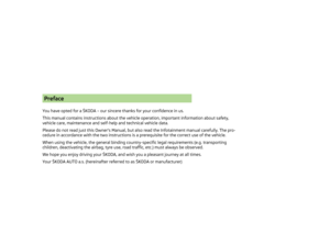 3
3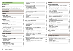 4
4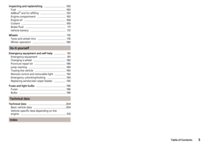 5
5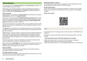 6
6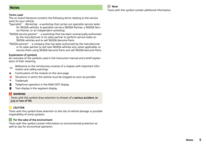 7
7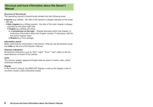 8
8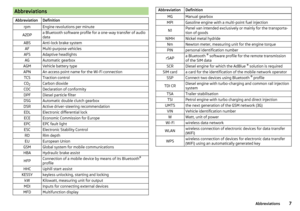 9
9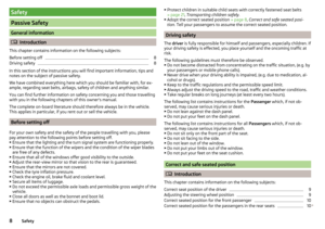 10
10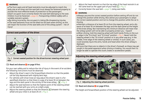 11
11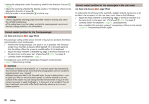 12
12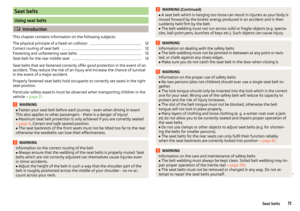 13
13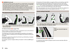 14
14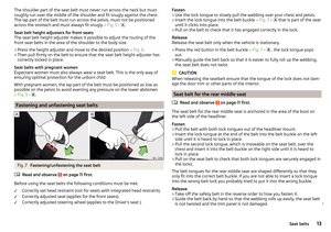 15
15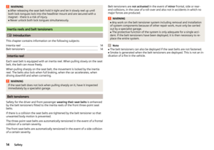 16
16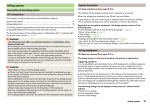 17
17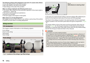 18
18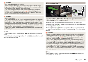 19
19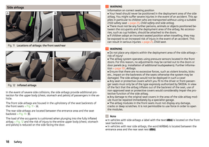 20
20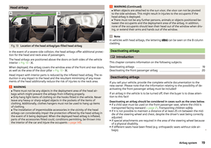 21
21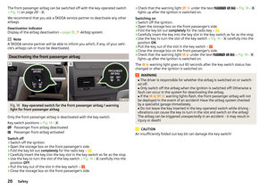 22
22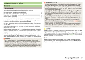 23
23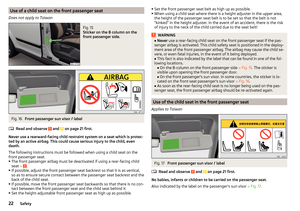 24
24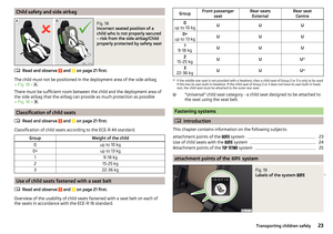 25
25 26
26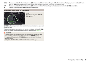 27
27 28
28 29
29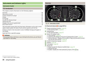 30
30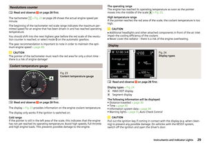 31
31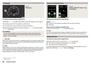 32
32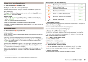 33
33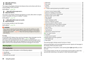 34
34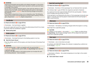 35
35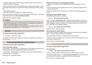 36
36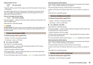 37
37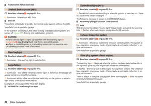 38
38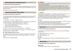 39
39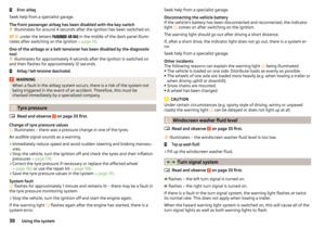 40
40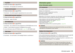 41
41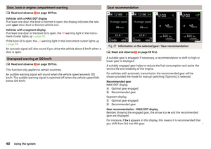 42
42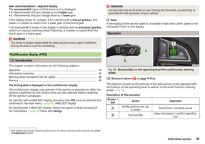 43
43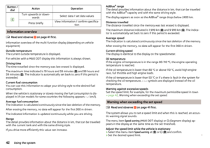 44
44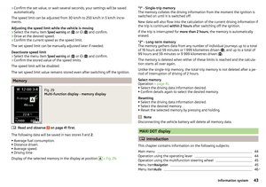 45
45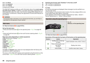 46
46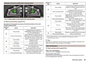 47
47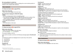 48
48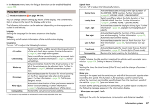 49
49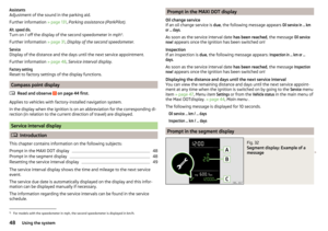 50
50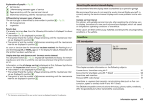 51
51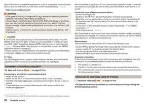 52
52 53
53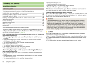 54
54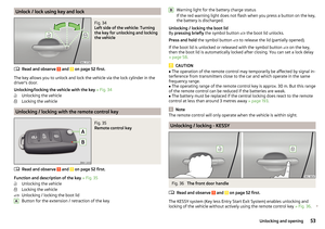 55
55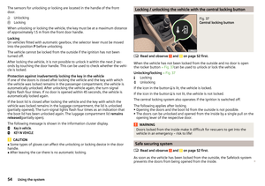 56
56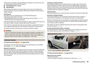 57
57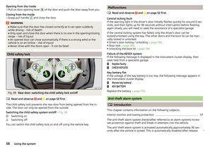 58
58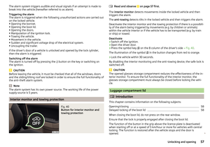 59
59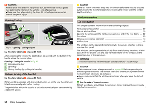 60
60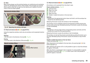 61
61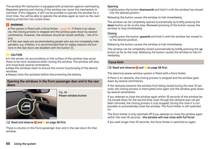 62
62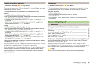 63
63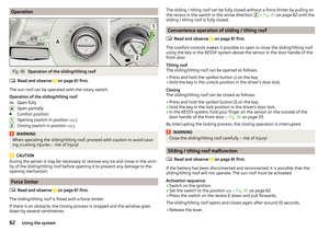 64
64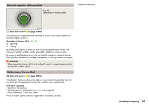 65
65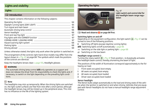 66
66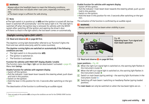 67
67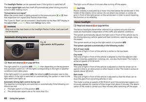 68
68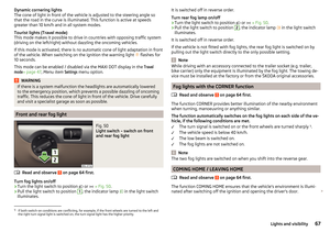 69
69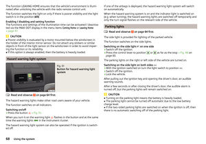 70
70 71
71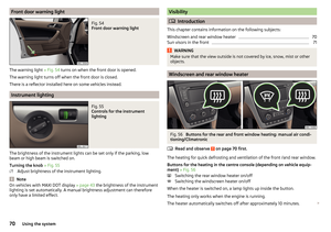 72
72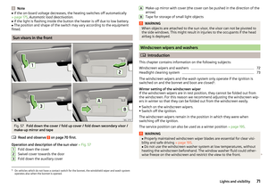 73
73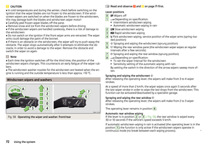 74
74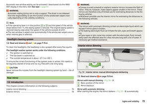 75
75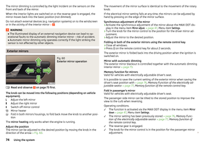 76
76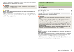 77
77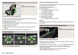 78
78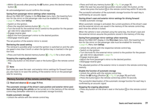 79
79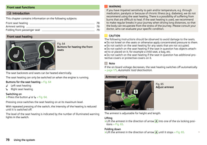 80
80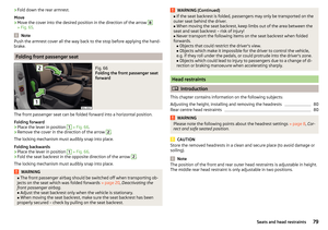 81
81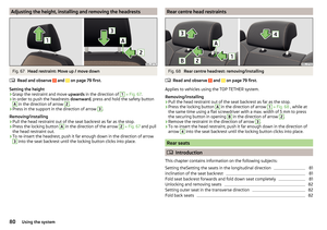 82
82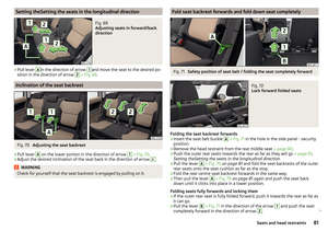 83
83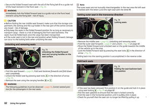 84
84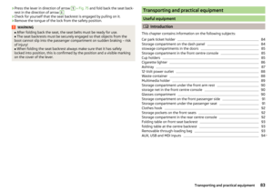 85
85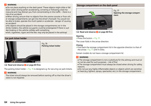 86
86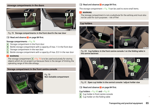 87
87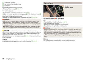 88
88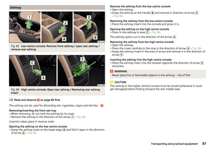 89
89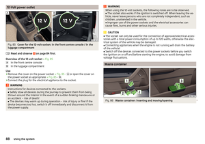 90
90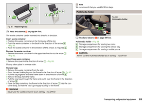 91
91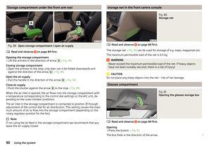 92
92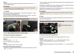 93
93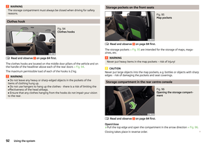 94
94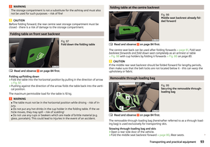 95
95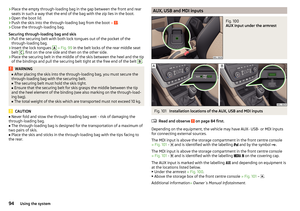 96
96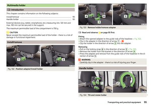 97
97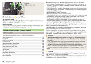 98
98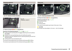 99
99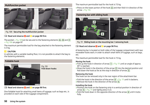 100
100 101
101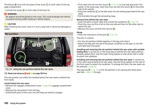 102
102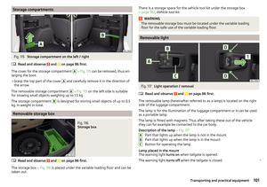 103
103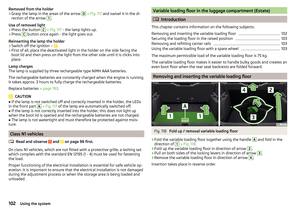 104
104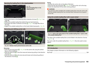 105
105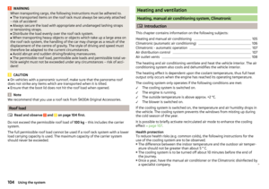 106
106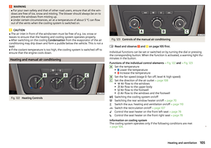 107
107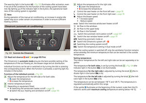 108
108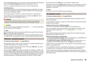 109
109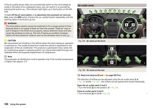 110
110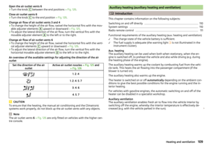 111
111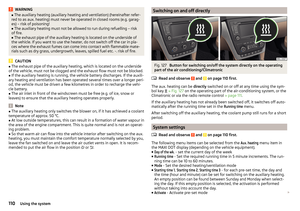 112
112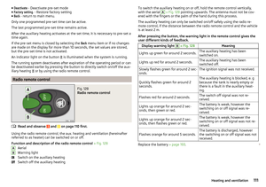 113
113 114
114 115
115 116
116 117
117 118
118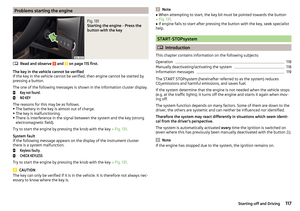 119
119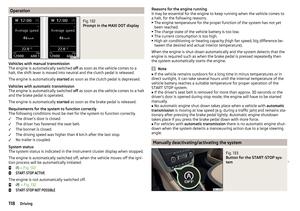 120
120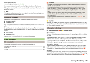 121
121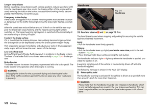 122
122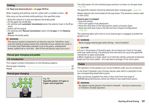 123
123 124
124 125
125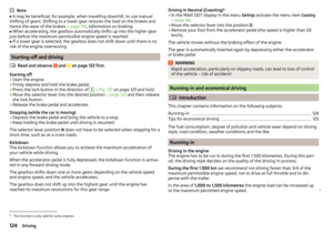 126
126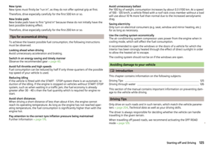 127
127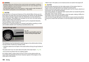 128
128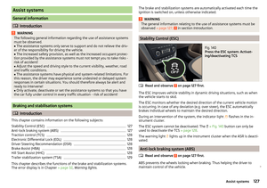 129
129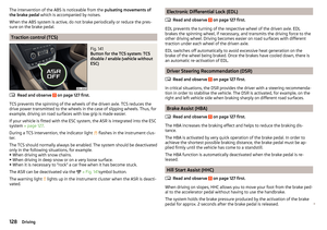 130
130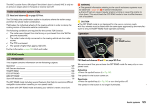 131
131 132
132 133
133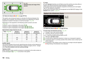 134
134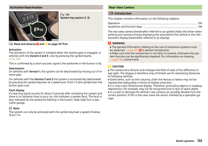 135
135 136
136 137
137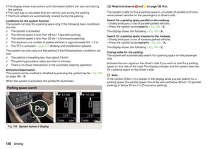 138
138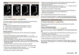 139
139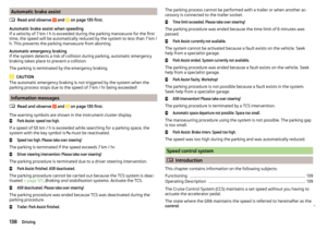 140
140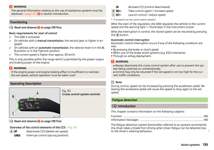 141
141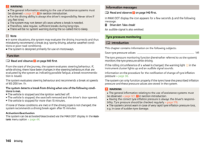 142
142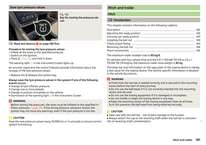 143
143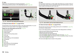 144
144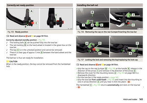 145
145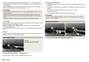 146
146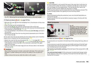 147
147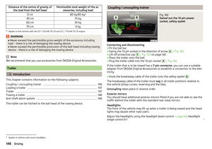 148
148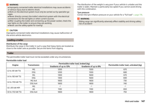 149
149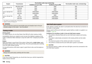 150
150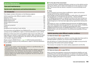 151
151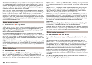 152
152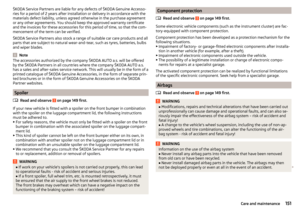 153
153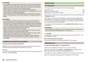 154
154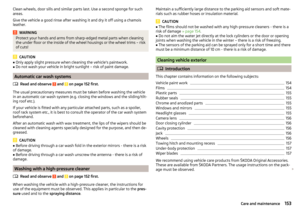 155
155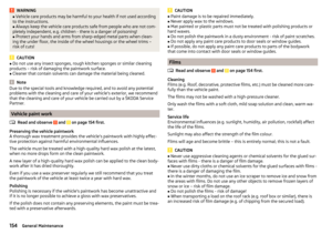 156
156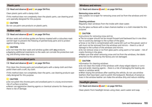 157
157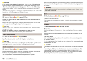 158
158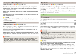 159
159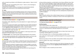 160
160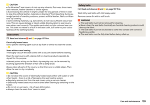 161
161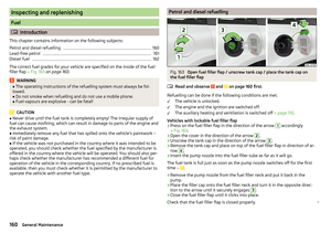 162
162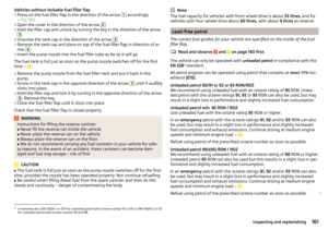 163
163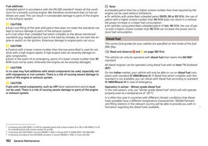 164
164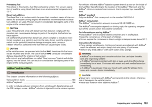 165
165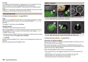 166
166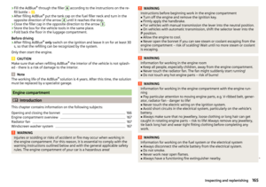 167
167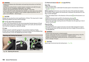 168
168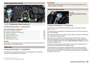 169
169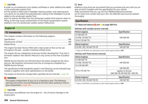 170
170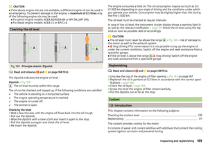 171
171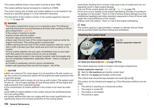 172
172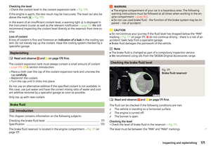 173
173 174
174 175
175 176
176 177
177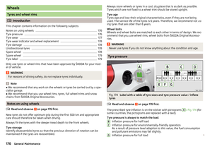 178
178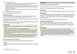 179
179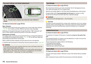 180
180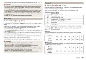 181
181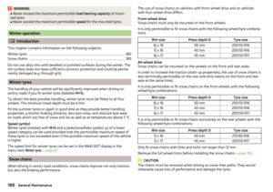 182
182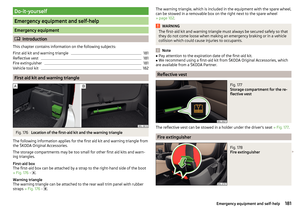 183
183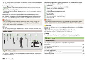 184
184 185
185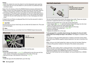 186
186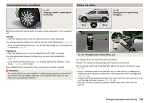 187
187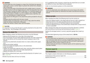 188
188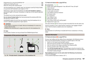 189
189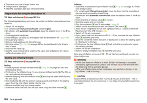 190
190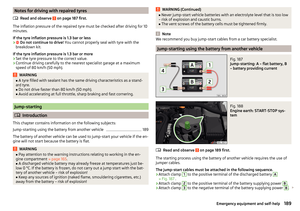 191
191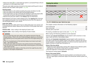 192
192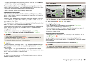 193
193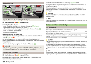 194
194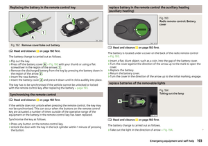 195
195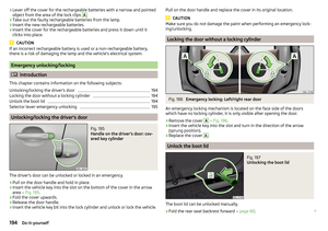 196
196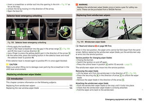 197
197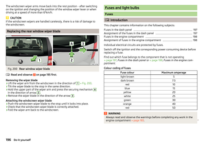 198
198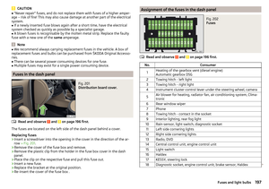 199
199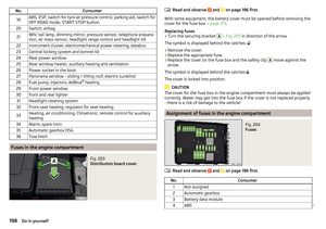 200
200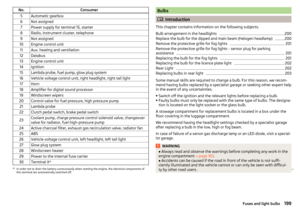 201
201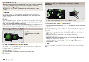 202
202 203
203 204
204 205
205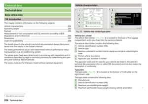 206
206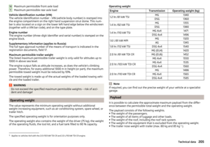 207
207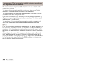 208
208 209
209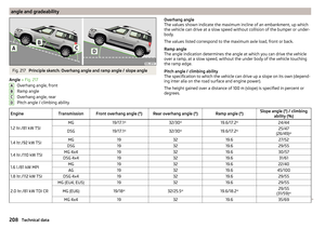 210
210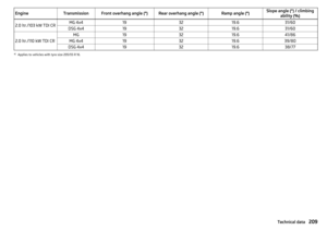 211
211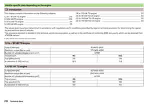 212
212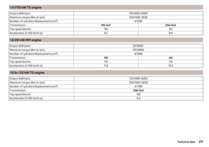 213
213 214
214 215
215 216
216 217
217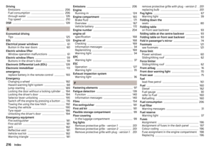 218
218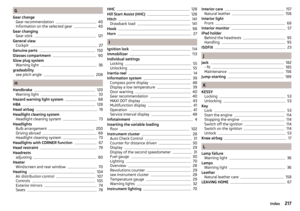 219
219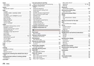 220
220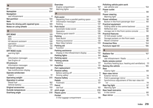 221
221 222
222 223
223 224
224 225
225 226
226 227
227 228
228 229
229 230
230 231
231