Page 97 of 232
 measuring min. 122 mm")
Multimedia holder
Introduction
This chapter contains information on the following subjects:
Install/remove
95
Handle holder
95
External devices (e.g. tablet, smartphone, etc.) measuring min. 122 mm and
max. 195 mm can be secured in the support.
The maximum permissible load of the compartment is 750 g.
CAUTION
Never exceed the maximum permissible load of the holder - there is a risk of
damage or functional impairment.
Install/remove
Fig. 102
Position adapter/install holder
Fig. 103
Remove holder/remove adapter
Read and observe
on page 95 first.
Fitting
›
Attach the opened adapter to the guide rods of the headrest » Fig. 102.
›
Clip in the adapter in the direction of arrow
1
» .
›
Clip the holder in the direction of arrow
2
into the adapter.
Removing
›
Pull on the locking strap
A
in the direction of arrow
3
» Fig. 103 .
›
Remove the holder from the bracket in the direction of arrow
4
.
›
Press the adapter and remove from the guide rods of the headrest in the di-
rection of arrow
5
.
WARNINGCarefully clip in the adapter - there is a risk of injuring your finger.
Handle holder
Fig. 104
Tilt and rotate holder
95Transporting and practical equipment
Page 98 of 232

Fig. 105
Adjust holder size
Read and observe on page 95 first.
Tilt and rotate holder
The holder may be tilted 30° in the direction of arrow
1
and rotated through
360° in the direction of arrow
2
» Fig. 104 .
Adjust holder size
›
Pull out the securing tab
A
in the direction of arrow
3
and move part
B
in
direction of arrow
4
to the desired position » Fig. 105.
Luggage compartment and transport of cargo
Introduction
This chapter contains information on the following subjects:
Fastening elements
97
Fixing nets
97
Multifunction pocket
98
Foldable hook
98
Fastening bar with sliding hook
98
Flexible storage compartment
99
Floor covering on both sides
99
Luggage compartment cover
99
Net partition
100
Storage compartments
101
Removable storage box
101
Removable light
101
Class N1 vehicles
102When transporting cargo, the following instructions must be adhered to ▶ When transporting heavy objects, the driving characteristics change due to
the shift in the centre of gravity. The speed and style of driving must be ad-
justed accordingly.
▶ The cargo should be stowed in the luggage compartment. To prevent it from
moving, it should be secured with suitable lashing straps to the lashing eyes
or secured with fixing nets.
▶ Distribute loads as evenly as possible.
▶ Place heavy objects as far forward as possible.
▶ The transported items must be stowed in such a way that no objects are able
to slip forward on sudden driving or braking manoeuvres – risk of injury!
▶ Tyre pressure should be adjusted for the load.
▶ When transporting loads in the luggage compartment that has been en-
larged by folding one of the rear seats forward, care should be taken to en-
sure the safety of passengers transported on the other rear seat.
In the event of an accident, even small and light objects gain so much kinetic
energy that they can cause severe injuries.
The magnitude of the kinetic energy is dependent on the speed at which the
vehicle is travelling and the weight of the object.
Example: In the event of a frontal collision at a speed of 50 km/h, an object
with a weight of 4.5 kg produces an energy, which corresponds to 20 times its
own weight. This means that it results in a weight of approx. 90 kg “ ”.WARNING■ Never exceed the maximum permissible load of the respective fasteners,
nets, hooks, etc., as heavy objects are not sufficiently secured - there is a
risk of injury!■
If the cargo is tied down with unsuitable or damaged lashing straps, inju-
ries can occur in the event of braking manoeuvres or accidents.
■
Loose cargo can be thrown forward during a sudden manoeuvre or in the
event of an accident and can injure the occupants or other road users.
■
Loose cargo could hit a deployed airbag and injure occupants – danger of
death!
CAUTION
■ Never exceed the maximum permissible load of the respective fasteners,
nets, hooks, etc. - these could be damaged.■
Please ensure that the heating elements for the rear window heater are not
damaged as a result of abrasive objects.
96Using the system
Page 99 of 232
Fastening elementsFig. 106
Fasteners: Version 1/version 2
Fig. 107
Fasteners: variant 3
Read and observe and on page 96 first.
Overview of the fastening elements » Fig. 106 and » Fig. 107
Lashing eyes for securing items of luggage, fastening nets and multifunc-
tion pocket
Fasteners for securing fastening nets and multifunction pocket
Fastening strip with integrated hook for attaching fastening nets and mul-
tifunction pocket
Lashing eyes for securing fastening nets
The maximum permissible load of the individual lashing eyes
A
is 350 kg.
The maximum permissible load of the individual lashing eyes
D
is 150 kg.
ABCDFixing netsFig. 108
Fastening examples for nets
Read and observe
and on page 96 first.
Fastening examples for nets » Fig. 108
Horizontal pocket
Floor net
Vertical pocket
The maximum permissible load of each of the nets is 1.5 kg.
CAUTION
Do not place any sharp objects in the nets – risk of net damage.ABC97Transporting and practical equipment
Page 100 of 232

Multifunction pocketFig. 109
Securing the multifunction pocket
Read and observe
and on page 96 first.
The pocket » Fig. 109can be secured to the fastening elements
A
,
B
and
C
» Fig. 106 on page 97 .
The maximum permissible load for the bag attached to the fastening element
is 3 kg.
CAUTION
In vehicles with a variable loading floor, it is not possible to attach the bag to
the fastening elements.
Foldable hook
Fig. 110
Fold down hooks
Read and observe and on page 96 first.
One foldable hook for attaching small items of luggage, such as bags etc., is
provided on each side of the luggage compartment.
The maximum permissible load for the hook is 7.5 kg.›
Press on the lower portion of the hook
A
and then fold it in direction of the
arrow » Fig. 110 .
Fastening bar with sliding hook
Fig. 111
Sliding hook on the mounting bar / removing hook
Read and observe
and on page 96 first.
A fastening bar is located on both sides of the luggage compartment with two moveable hooks each, in order to attach small items of luggage, such as bags,
etc.
The maximum permissible load for the hook is 7.5 kg.
Moving the hook
›
Fold up the hook in direction of arrow
1
» Fig. 111 until an angle of approx.
45° is reached.
›
Move the hook in the direction of the arrow
2
into the desired position and
fold down the hook as far as the stop in direction of arrow
3
.
Removing the hook
The hook can be removed only in the rear region of the attachment bar.
›
Fold the hook in the direction of the arrow
4
» Fig. 111 until it slackens.
›
Remove the hook in the direction of the arrow
5
.
Installing the hook
›
Position the hook on the fastening strip in a vertical position in direction of
arrow
5
» Fig. 111 and lightly press it on.
›
Fold the hook down in the opposite direction of the arrow
4
until it locks
fully.
98Using the system
Page 101 of 232

Flexible storage compartmentFig. 112
Flexible storage compartment
Read and observe and on page 96 first.
The flexible storage compartment can be installed on the right-hand side ofthe boot » Fig. 112.
The storage compartment is designed for storing small objects with a maxi-
mum total weight of 8 kg.
Fitting
›
Place both ends of the storage compartment into the openings on the right
side panel of the luggage compartment.
›
Push the storage compartment down to lock it.
Removing
›
Grasp the storage compartment on the two upper corners.
›
Press the upper corners inwards and release the storage compartment by
pulling upwards.
›
Remove the storage compartment by pulling towards you.
CAUTION
The flexible storage compartment cannot be installed on vehicles with the var-
iable loading floor.
Floor covering on both sides
Read and observe
and on page 96 first.
You can fit a double-sided floor covering in the luggage compartment.
One side of the double-sided floor covering is made of fabric, the other side is
washable (easy to maintain).
The washable side is used to transport wet or dirty items.
NoteFor easier turning of the covering, use the loop attached.
Luggage compartment cover
Fig. 113
Remove the luggage compartment cover
Read and observe
and on page 96 first.
If the support straps
A
» Fig. 113 are attached to the boot lid, then opening
the lid will raise the boot lid cover (hereafter referred to as cover).
The boot cover can be removed if you want to transport bulky goods.
Removing
›
Fold the seat backrests forward a little to make it easier to remove the lug-
gage compartment cover » page 81, inclination of the seat backrest .
›
On both sides of the boot lid, unhook the straps
A
in the direction of arrow
1
» Fig. 113 .
›
Place the cover in the horizontal position.
›
Press on the two sides to the underside of the cover in the region of the
studs
C
in the direction of arrow
2
.
›
Fold the slackened front part of the boot cover over the head restraints of
the rear seats.
›
Slightly tilt the boot cover and remove it to the rear.
Fitting
›
Place the cover on the contact surfaces of the side trim panel.
›
Position the mounts on the cover
B
onto the side trim panel via pins
C
» Fig. 113 .
›
Press on the two sides to the upper side of the cover in the region of the
studs
C
.
99Transporting and practical equipment
Page 102 of 232

The fixture B must lock into place of the studs C on both sides of the lug-
gage compartment.›
Unhook the straps
A
on both sides of the boot lid.
WARNINGNo objects should be placed on the cover. This could endanger the vehicle
occupants during sudden braking or vehicle impact.
CAUTION
After removing the cover, store it in such a way that it cannot be damaged or
soiled.
Net partition
Fig. 114
Using the net partition behind the rear seats
Read and observe
and on page 96 first.
The net partition can either be installed behind the rear seats or behind the front seats.
Install behind the rear seats
›
Remove the luggage compartment cover » page 99, Luggage compartment
cover .
›
Remove the net partition from the bag.
›
Unfold both parts of the cross rod until they are heard to engage.
›First insert the rod into the mount B
» Fig. 114 on one side and push it for-
wards. In the same way, insert the cross rod into the mount B on the other
side of the vehicle.›
Hang the carabines
C
at the belt ends into the lashing eyes behind the rear
seats.
›
Pull the belts through the tensioning clasp.
Remove from behind the rear seats
›
Undo the belts on both sides and unhook the carabiners
C
» Fig. 114 .
›
Push the cross rod first of all on the one side and then on the other side to-
wards the rear.
›
Remove the cross rod from the mounts
B
.
Merge
›
Press the red button of the joint
A
» Fig. 114 .
The joint is undone.
›
Put the net partition folded together in the bag and close it.
›
Attach the bag with the aid of the plastic carabines to the eyes on the left
and right boot trim panel.
Installing and removing the net partition behind the rear seats with variable
loading floor is carried out in the same way as behind the rear seats without
variable loading floor. Use the lower fixing eyelets on the carrier rails in order
to attach the carabines.
Installing and removing the net partition behind the rear seats is carried out
in the same way as behind the rear seats. Use the fixing eyelets on the rear of
the front seats to attach the carabines. To enlarge the boot, the rear seats can
be removed » page 82.
The opening
D
» Fig. 114 in the net partition is for passing the three-point
seat belt » page 13 through.
100Using the system
Page 103 of 232

Storage compartmentsFig. 115
Storage compartment on the left / right
Read and observe
and on page 96 first.
The cover for the storage compartment
A
» Fig. 115 can be removed, thus en-
larging the boot.
›
Grasp the top part of the cover
A
and carefully remove it in the direction of
the arrow.
The removable storage compartment
A
» Fig. 115 on the left side is suitable
for stowing small objects weighing up to 1.5 kg.
The storage compartment
B
is designed for storing small objects of up to 0.5
kg. in weight in total.
Removable storage box
Fig. 116
Storage box
Read and observe and on page 96 first.
The storage box » Fig. 116 is placed under the variable loading floor and can be
taken out.
There is a storage space for the vehicle tool kit under the storage box » page 182 , Vehicle tool kit .WARNINGThe removable storage box must be located under the variable loading
floor for the safe use of the variable loading floor.
Removable light
Fig. 117
Light operation / removal
Read and observe
and on page 96 first.
The removable lamp (hereinafter referred to as a lamp) is located on the right side of the luggage compartment.
The lamp is for the illumination of the luggage compartment or it can be used
as a portable lamp.
The lamp is fitted with magnets. Thus after taking these out of the vehicle
they can for example be connected to the car body.
Description of the lamp » Fig. 117
Part that lights up when the lamp is not in the mount
Part that lights up when the lamp is in the mount
Button for operating the lamp
Lamp placed in the mount
The warning light turns on when tailgate is opened.
The warning light turns off when the tailgate is closed.
ABC101Transporting and practical equipment
Page 104 of 232

Removed from the holder›Grasp the lamp in the areas of the arrow D » Fig. 117 and swivel it in the di-
rection of the arrow 1
.
Use of removed light
›
Press the button
C
» Fig. 117 - the lamp lights up.
›
Press
C
button once again - the light goes out.
Reinserting the lamp the holder
›
Switch off the ignition » .
›
First of all, place the deactivated light in the holder on the side facing the
boot lid and then press on the light from the other side until it is clicks into
place.
Lamp charges
The lamp is supplied by three rechargeable type NiMH AAA batteries.
The rechargeable batteries are constantly charged when the engine is running.
It takes approx. 3 hours to fully charge the rechargeable batteries.
Replace batteries » page 193.
CAUTION
■
If the lamp is not switched off and correctly inserted in the holder, the LEDs
in the front part A » Fig. 117 of the lamp are automatically switched off.■
If the lamp is not correctly inserted into the holder, this does not light up
when the boot lid is opened and the rechargeable batteries are not charged.
■
The lamp is not watertight and must therefore be protected against mois-
ture.
Class N1 vehicles
Read and observe
and on page 96 first.
On class N1 vehicles, which are not fitted with a protective grille, a lashing set
which complies with the standard EN 12195 (1 - 4) must be used for fastening
the load.
Proper functioning of the electrical installation is essential for safe vehicle op-
eration. It is important to ensure that the electrical installation is not damaged
during the adjustment process or when the storage area is being loaded and
unloaded.
Variable loading floor in the luggage compartment (Estate)
Introduction
This chapter contains information on the following subjects:
Removing and inserting the variable loading floor
102
Securing the loading floor in the raised position
103
Removing and refitting carrier rails
103
Using the variable loading floor with a spare wheel
103
The maximum permissible load of the variable loading floor is 75 kg.
The variable loading floor makes it easier to handle bulky goods and creates an even boot floor when the rear seat backrests are folded forward.
Removing and inserting the variable loading floor
Fig. 118
Fold up / removal variable loading floor
›
Fold the variable loading floor together using the handle
A
and fold in the
direction of
1
» Fig. 118 .
›
Fold up the variable loading floor in direction of arrow
2
.
›
Pull on both sides of the locking levers in direction of arrow
3
.
›
Remove the variable loading floor in direction of arrow
4
.
Insertion takes place in reverse order.
102Using the system
 1
1 2
2 3
3 4
4 5
5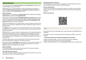 6
6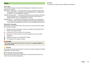 7
7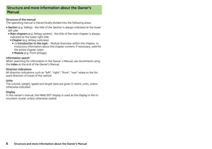 8
8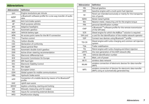 9
9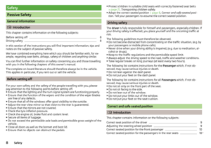 10
10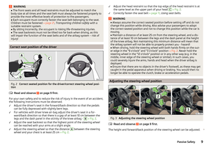 11
11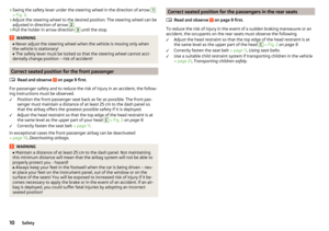 12
12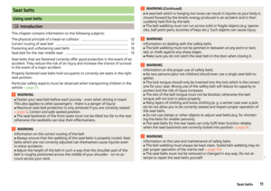 13
13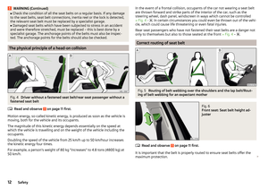 14
14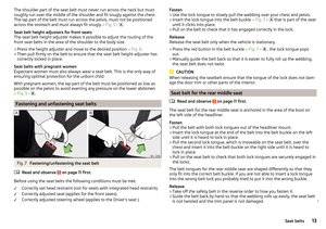 15
15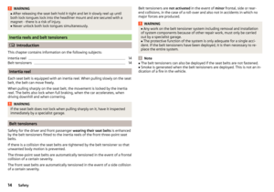 16
16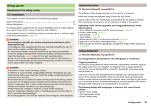 17
17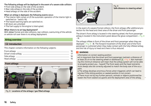 18
18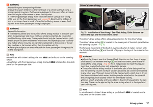 19
19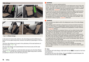 20
20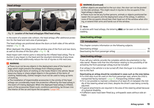 21
21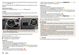 22
22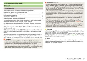 23
23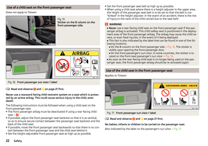 24
24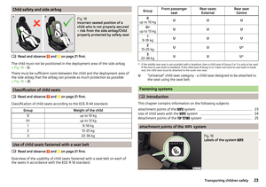 25
25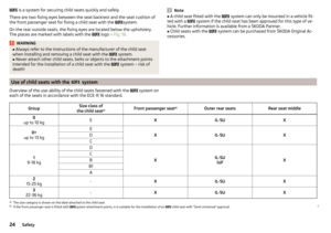 26
26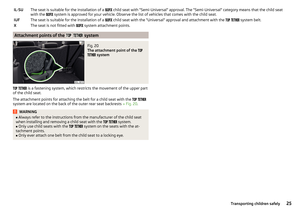 27
27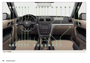 28
28 29
29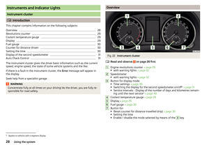 30
30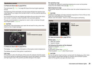 31
31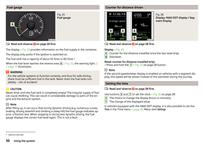 32
32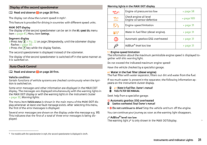 33
33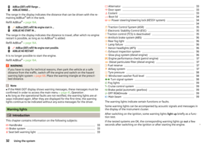 34
34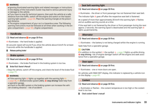 35
35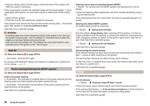 36
36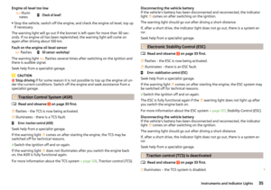 37
37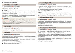 38
38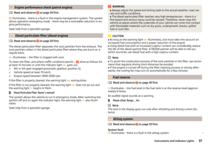 39
39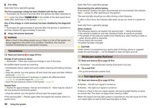 40
40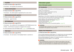 41
41 42
42 43
43 44
44 45
45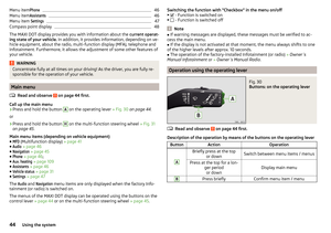 46
46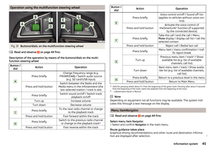 47
47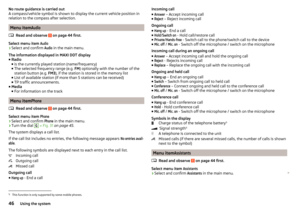 48
48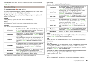 49
49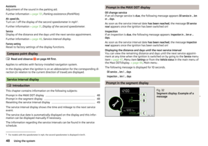 50
50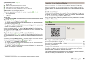 51
51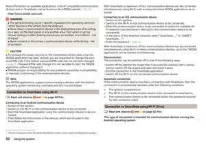 52
52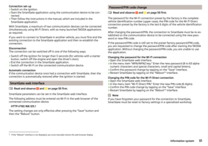 53
53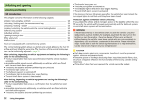 54
54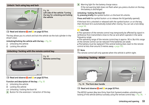 55
55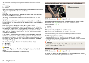 56
56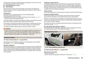 57
57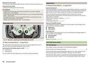 58
58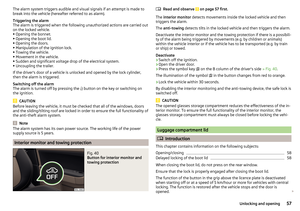 59
59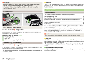 60
60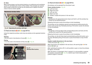 61
61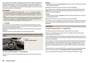 62
62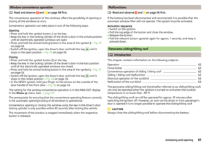 63
63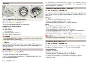 64
64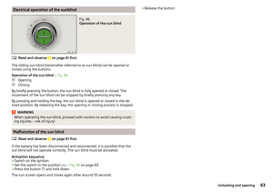 65
65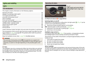 66
66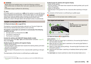 67
67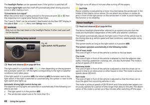 68
68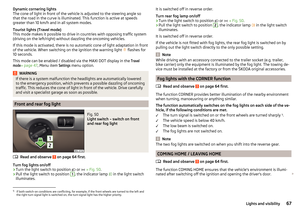 69
69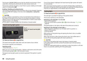 70
70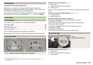 71
71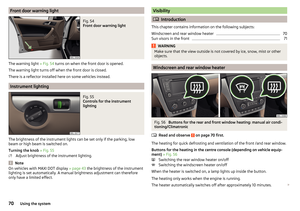 72
72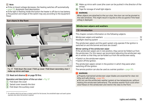 73
73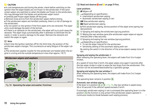 74
74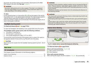 75
75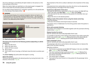 76
76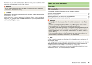 77
77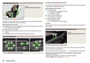 78
78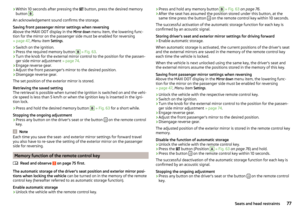 79
79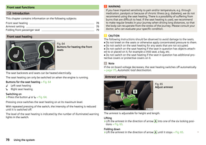 80
80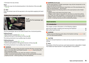 81
81 82
82 83
83 84
84 85
85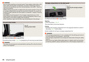 86
86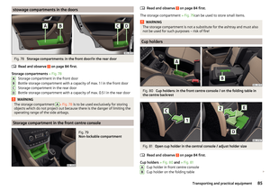 87
87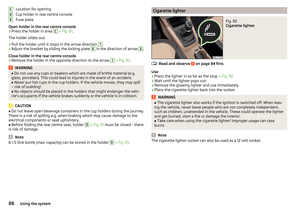 88
88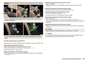 89
89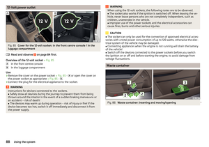 90
90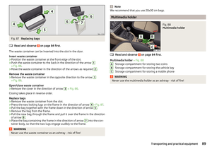 91
91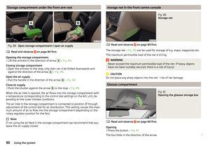 92
92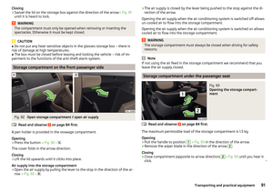 93
93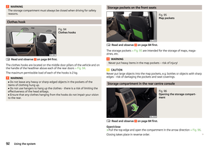 94
94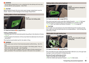 95
95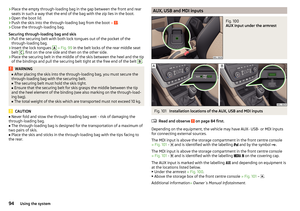 96
96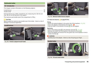 97
97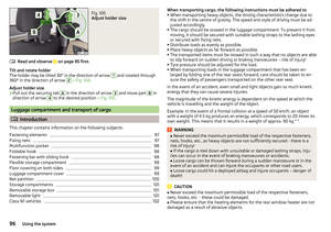 98
98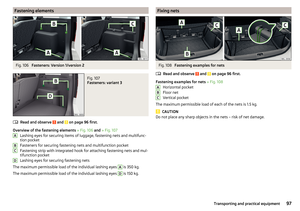 99
99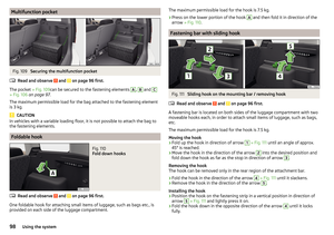 100
100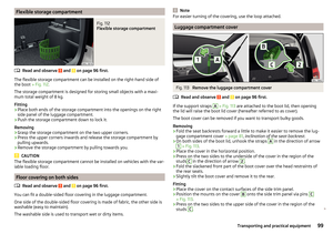 101
101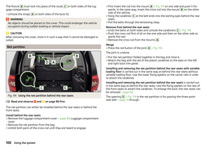 102
102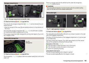 103
103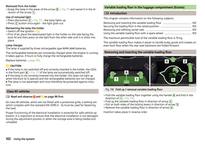 104
104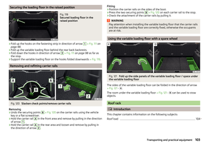 105
105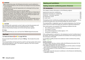 106
106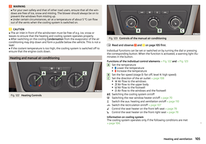 107
107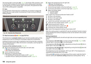 108
108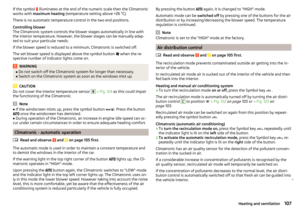 109
109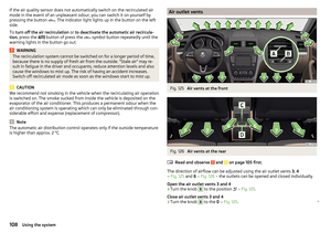 110
110 111
111 112
112 113
113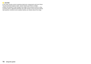 114
114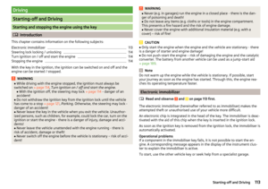 115
115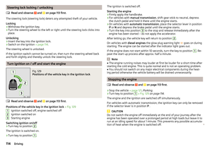 116
116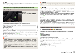 117
117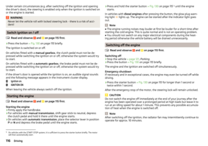 118
118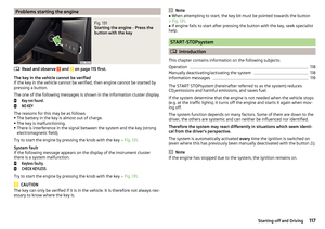 119
119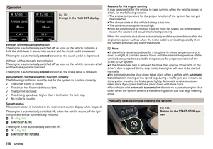 120
120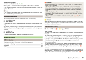 121
121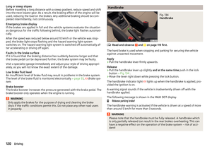 122
122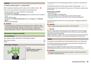 123
123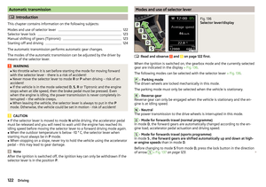 124
124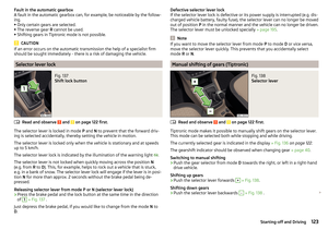 125
125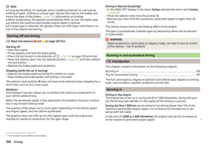 126
126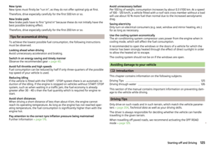 127
127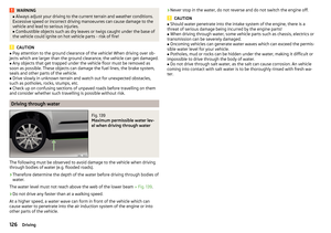 128
128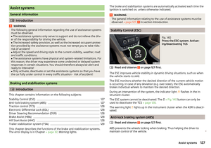 129
129 130
130 131
131 132
132 133
133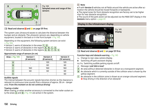 134
134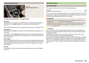 135
135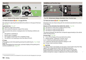 136
136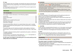 137
137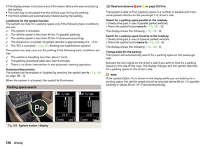 138
138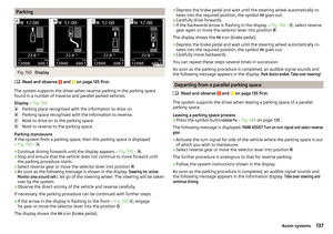 139
139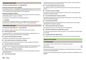 140
140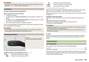 141
141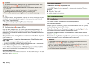 142
142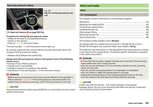 143
143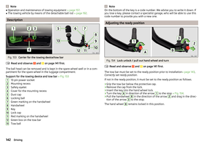 144
144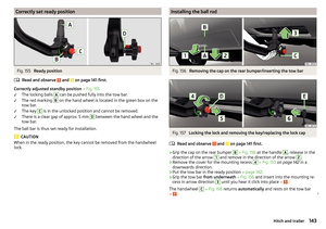 145
145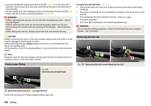 146
146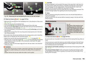 147
147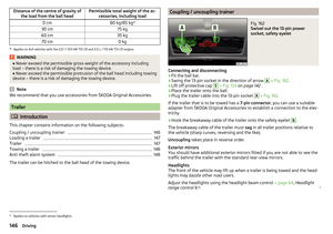 148
148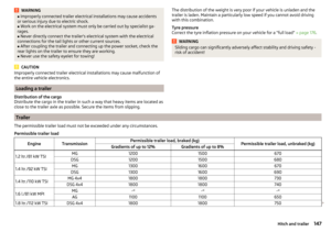 149
149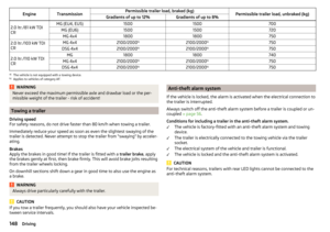 150
150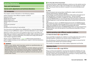 151
151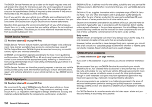 152
152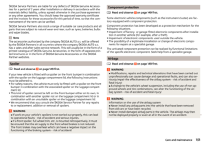 153
153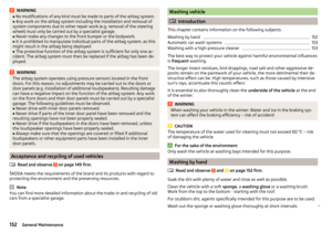 154
154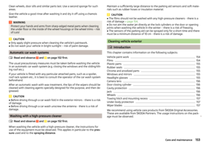 155
155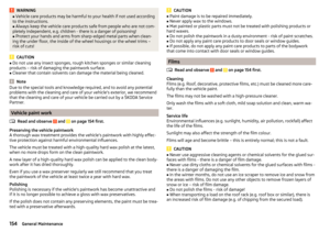 156
156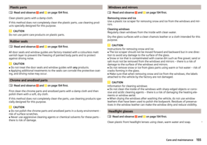 157
157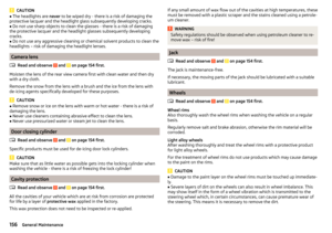 158
158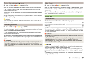 159
159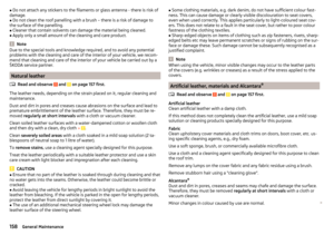 160
160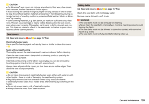 161
161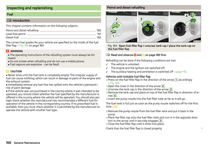 162
162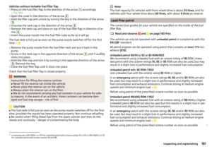 163
163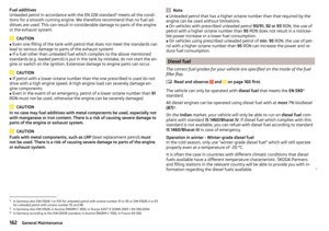 164
164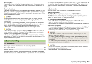 165
165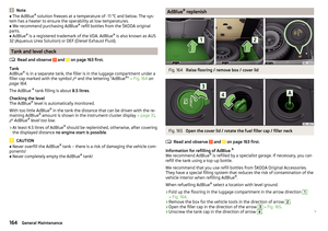 166
166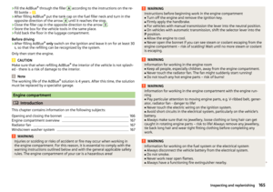 167
167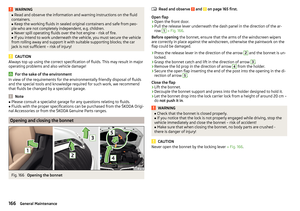 168
168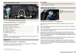 169
169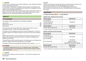 170
170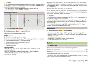 171
171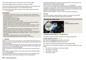 172
172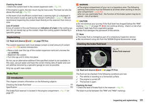 173
173 174
174 175
175 176
176 177
177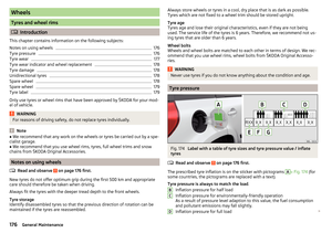 178
178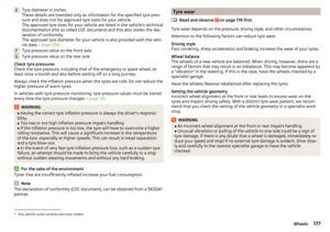 179
179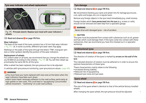 180
180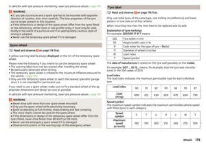 181
181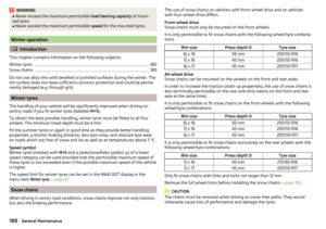 182
182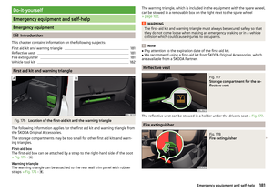 183
183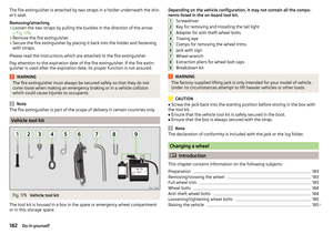 184
184 185
185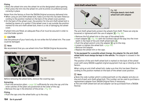 186
186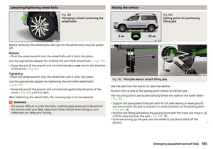 187
187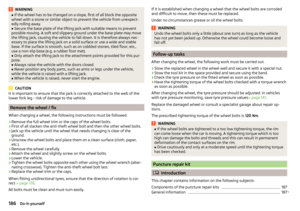 188
188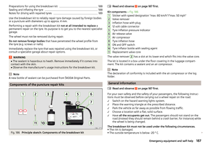 189
189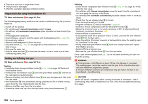 190
190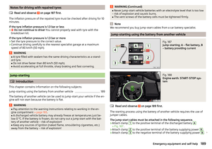 191
191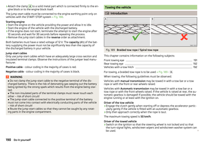 192
192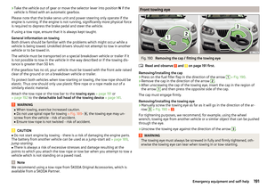 193
193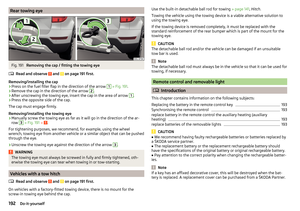 194
194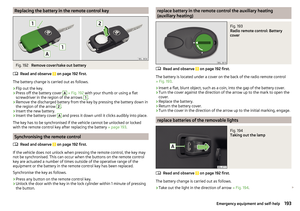 195
195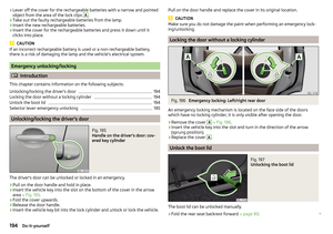 196
196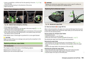 197
197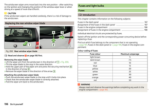 198
198 199
199 200
200 201
201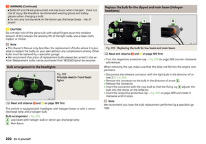 202
202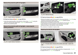 203
203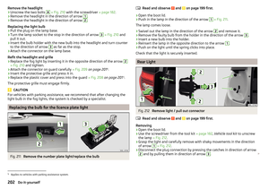 204
204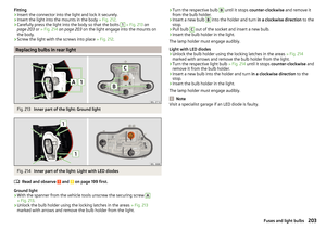 205
205 206
206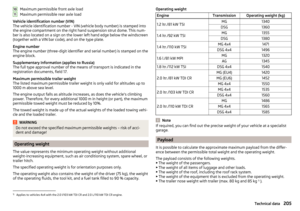 207
207 208
208 209
209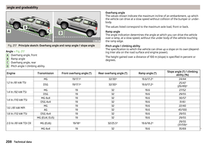 210
210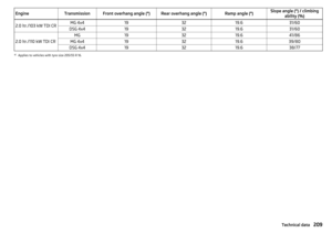 211
211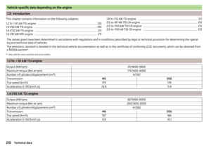 212
212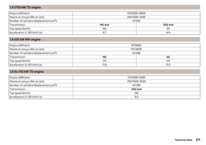 213
213 214
214 215
215 216
216 217
217 218
218 219
219 220
220 221
221 222
222 223
223 224
224 225
225 226
226 227
227 228
228 229
229 230
230 231
231