2015 MERCEDES-BENZ GLC SUV lock
[x] Cancel search: lockPage 256 of 497
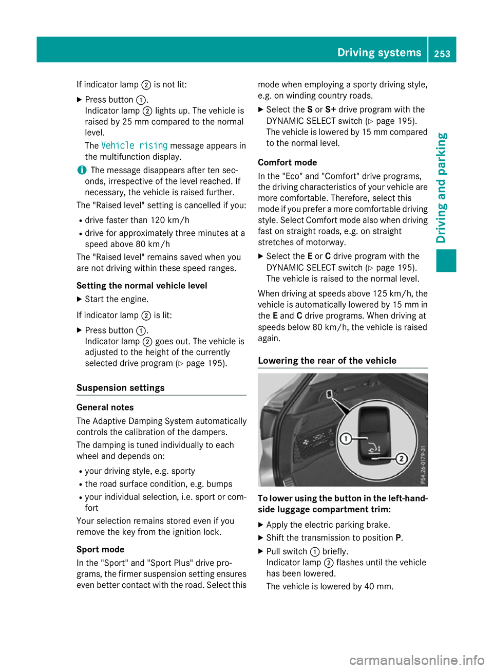
If indicator lamp
;is not lit:
X Press button :.
Indicator lamp ;lights up. The vehicle is
raised by 25 mm compared to the normal
level.
The Vehicle rising Vehicle rising message appears in
the multifunction display.
i The message disappears after ten sec-
onds, irrespective of the level reached. If
necessary, the vehicle is raised further.
The "Raised level" setting is cancelled if you:
R drive faster than 120 km/h
R drive for approximately three minutes at a
speed above 80 km/h
The "Raised level" remains saved when you
are not driving within these speed ranges.
Setting the normal vehicle level X Start the engine.
If indicator lamp ;is lit:
X Press button :.
Indicator lamp ;goes out. The vehicle is
adjusted to the height of the currently
selected drive program (Y page 195).
Suspension settings General notes
The Adaptive Damping System automatically
controls the calibration of the dampers.
The damping is tuned individually to each
wheel and depends on:
R your driving style, e.g. sporty
R the road surface condition, e.g. bumps
R your individual selection, i.e. sport or com-
fort
Your selection remains stored even if you
remove the key from the ignition lock.
Sport mode
In the "Sport" and "Sport Plus" drive pro-
grams, the firmer suspension setting ensures even better contact with the road. Select this mode when employing a sporty driving style,
e.g. on winding country roads.
X Select the Sor S+ drive program with the
DYNAMIC SELECT switch (Y page 195).
The vehicle is lowered by 15 mm compared
to the normal level.
Comfort mode
In the "Eco" and "Comfort" drive programs,
the driving characteristics of your vehicle are
more comfortable. Therefore, select this
mode if you prefer a more comfortable driving
style. Select Comfort mode also when driving fast on straight roads, e.g. on straight
stretches of motorway.
X Select the Eor Cdrive program with the
DYNAMIC SELECT switch (Y page 195).
The vehicle is raised to the normal level.
When driving at speeds above 125 km/h, the
vehicle is automatically lowered by 15 mm in the Eand Cdrive programs. When driving at
speeds below 80 km/h, the vehicle is raised
again.
Lowering the rear of the vehicle To lower using the button in the left-hand-
side luggage compartment trim:
X Apply the electric parking brake.
X Shift the transmission to position P.
X Pull switch :briefly.
Indicator lamp ;flashes until the vehicle
has been lowered.
The vehicle is lowered by 40 mm. Driving systems
253Driving and parking Z
Page 259 of 497
Rear sensors
Centre Approx. 120 cm
Corners Approx. 80 cm
Minimum distance
Centre Approx. 20 cm
Corners Approx. 15 cm
If there is an obstacle within this range, the
relevant warning displays light up and a warn- ing tone sounds. If the distance falls below
the minimum, the distance may no longer be
shown.
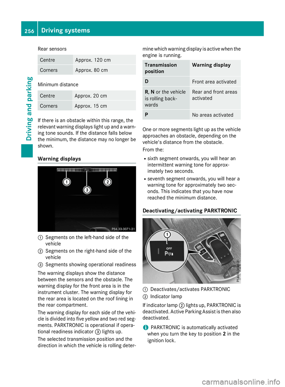
Warning displays :
Segments on the left-hand side of the
vehicle
; Segments on the right-hand side of the
vehicle
= Segments showing operational readiness
The warning displays show the distance
between the sensors and the obstacle. The
warning display for the front area is in the
instrument cluster. The warning display for
the rear area is located on the roof lining in
the rear compartment.
The warning display for each side of the vehi-
cle is divided into five yellow and two red seg- ments. PARKTRONIC is operational if opera-
tional readiness indicator =lights up.
The selected transmission position and the
direction in which the vehicle is rolling deter- mine which warning display is active when the
engine is running. Transmission
position Warning display
D
Front area activated
R,
Nor the vehicle
is rolling back-
wards Rear and front areas
activated
P
No areas activated
One or more segments light up as the vehicle
approaches an obstacle, depending on the
vehicle's distance from the obstacle.
From the:
R sixth segment onwards, you will hear an
intermittent warning tone for approx-
imately two seconds.
R seventh segment onwards, you will hear a
warning tone for approximately two sec-
onds. This indicates that you have now
reached the minimum distance.
Deactivating/activating PARKTRONIC :
Deactivates/activates PARKTRONIC
; Indicator lamp
If indicator lamp ;lights up, PARKTRONIC is
deactivated. Active Parking Assist is then also
deactivated.
i PARKTRONIC is automatically activated
when you turn the key to position 2in the
ignition lock. 256
Driving systemsDriving and pa
rking
Page 261 of 497
sharp angle. Otherwise, you may damage
the wheels or tyres.
Active Parking Assist may also display spaces not suitable for parking, e.g.:
R parking or stopping restrictions
R in front of driveways or entrances and exits
R unsuitable surfaces
Parking tips:
R on narrow roads, drive as closely as possi-
ble past the parking space
R parking spaces that are littered or over-
grown might be identified or measured
incorrectly
R parking spaces that are partially occupied
by trailer drawbars might not be identified
as such or be measured incorrectly
R snowfall or heavy rain may lead to a parking
space being measured inaccurately
R pay attention to the PARKTRONIC
(Y page 256) warning messages during the
parking procedure.
R you can intervene in the steering procedure
to correct it at any time. Active Parking
Assist will then be cancelled
R when transporting a load which protrudes
from your vehicle, you should not use
Active Parking Assist
R never use Active Parking Assist when snow
chains are fitted
R make sure that the tyre pressures are
always correct. This has a direct influence
on the parking characteristics of the vehi-
cle.
Use Active Parking Assist for parking spaces
that are:
R parallel or at right angles to the direction of
travel
R on straight roads, not bends
R on the same level as the road, e.g. not on
the pavement Detecting parking spaces Objects located above the height range of
Active Parking Assist will not be detected
when the parking space is measured. These
are not taken into account when the parking
procedure is calculated, e.g. overhanging
loads, tail sections or loading ramps of goods
vehicles. G
WARNING
If there are objects above the detection range:
R Active Park Assist may steer too early
R the vehicle may not stop in front of these
objects
This could cause a collision. There is a risk of
an accident.
If objects are located above the detection
range, stop and deactivate Active Parking
Assist.
For further information on the detection
range (Y page 255).
Active Parking Assist does not assist you
parking in spaces at right angles to the direc-
tion of travel if:
R two parking spaces are located directly
next to one another
R the parking space is directly next to a low
obstacle such as a low kerb
R you forward park
Active Parking Assist does not assist you
parking in spaces that are parallel or at right
angles to the direction of travel if:
R the parking space is on a kerb
R the system reads the parking space as
being blocked, for example by foliage or
grass paving blocks
R the area is too small for the vehicle to
manoeuvre into
R the parking space is bordered by an obsta-
cle, e.g. a tree, a post or a trailer 258
Driving systemsDriving and parking
Page 266 of 497
Activating/deactivating the reversing
camera X
To activate: make sure that the key is in
position 2in the ignition lock.
X Make sure that the Activation by R
Activation by R
gear
gear function is selected in Audio 20 or
COMAND Online (see the Digital Owner's
Manual).
X Engage reverse gear.
The reversing camera flap opens. The area
behind the vehicle is shown with guide lines
in the Audio 20 or COMAND Online display.
The image from the reversing camera is
available throughout the manoeuvring
process.
X To change the function mode for vehi-
cles with trailer tow hitch: using the
Audio 20 or COMAND Online controller,
select symbol :for the "Reverse parking"
function or symbol ;for "Coupling up a
trailer".
The symbol of the selected function is high-
lighted.
To deactivate: the reversing camera deacti-
vates if you shift the transmission to Por after
driving forwards a short distance. Messages in the Audio 20 or COMAND
Online display The reversing camera may show a distorted
view of obstacles or show them incorrectly or
not at all. Obstacles are not shown by the
reversing camera in the following locations:
R very close to the rear bumper
R under the rear bumper
R in the area immediately above the boot lid
handle or tailgate handle
! Objects not at ground level may appear to
be further away than they actually are, e.g.:
R the bumper of a parked vehicle
R the drawbar of a trailer
R the ball coupling of a trailer tow hitch
R the rear section of an HGV
R a slanted post
Use the guidelines only for orientation.
Approach objects no further than the bot-
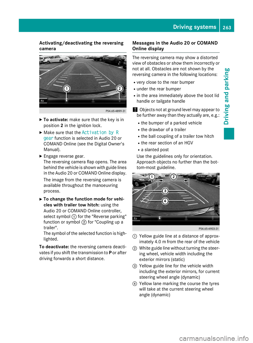
tom-most guideline. :
Yellow guide line at a distance of approx-
imately 4.0 mfrom the rear of the vehicle
; White guide line without turning the steer-
ing wheel, vehicle width including the
exterior mirrors (static)
= Yellow guide line for the vehicle width
including the exterior mirrors, for current
steering wheel angle (dynamic)
? Yellow lane marking the course the tyres
will take at the current steering wheel
angle (dynamic) Driving systems
263Driving and parking Z
Page 272 of 497
Switching on the 360° camera using
Audio 20 or COMAND Online X
To select 360° camera
360° camera in the vehicle car-
ousel: turn and press the controller.
The following appears depending on
whether transmission position Dor Ris
selected:
R a split-screen with top view and the
image from the front camera or
R a split-screen with top view and the
image from the reversing camera
Activating the 360° camera using
reverse gear You can show images from the 360° camera
automatically by engaging reverse gear.
X Make sure that the key is in position 2in the
ignition lock.
X Make sure that the Activation by R Activation by R
gear
gear function is selected in Audio 20 or
COMAND Online (see the Digital Owner's
Manual).
X To show the 360° camera image: engage
reverse gear.
The area behind the vehicle is shown in the
Audio 20 or COMAND display in split-
screen mode. You see the top view of the
vehicle and the image from the reversing
camera.
Selecting the split-screen view or full
screen mode Switching between split screen views:
X To switch to the line with the vehicle icons:
slide 5the controller.
X To select a vehicle icon: turn the controller.
Switching to full screen mode:
X 180° view
180° view Turn and press the controller. i
The full screen option is only available in
the following views:
R Top view with image from the reversing
camera
R Top view with image from the front cam-
era
Displays in the Audio 20 or COMAND
display Important safety notes
The camera system may show a distorted
view of obstacles or show them incorrectly or
not at all. Obstacles are not shown by the
system in the following locations:
R under the front and rear bumpers
R very close to the front and rear bumpers
R in the area immediately above the boot lid
handle or tailgate handle
R very close to the exterior mirrors
R in the transitional areas between the vari-
ous cameras in the virtual top view
! Objects not at ground level may appear to
be further away than they actually are, e.g.:
R the bumper of a parked vehicle
R the drawbar of a trailer
R the ball coupling of a trailer tow hitch
R the rear section of an HGV
R a slanted post
Use the guidelines only for orientation.
Approach objects no further than the bot-
tom-most guideline. Driving systems
269Driving and parking Z
Page 281 of 497
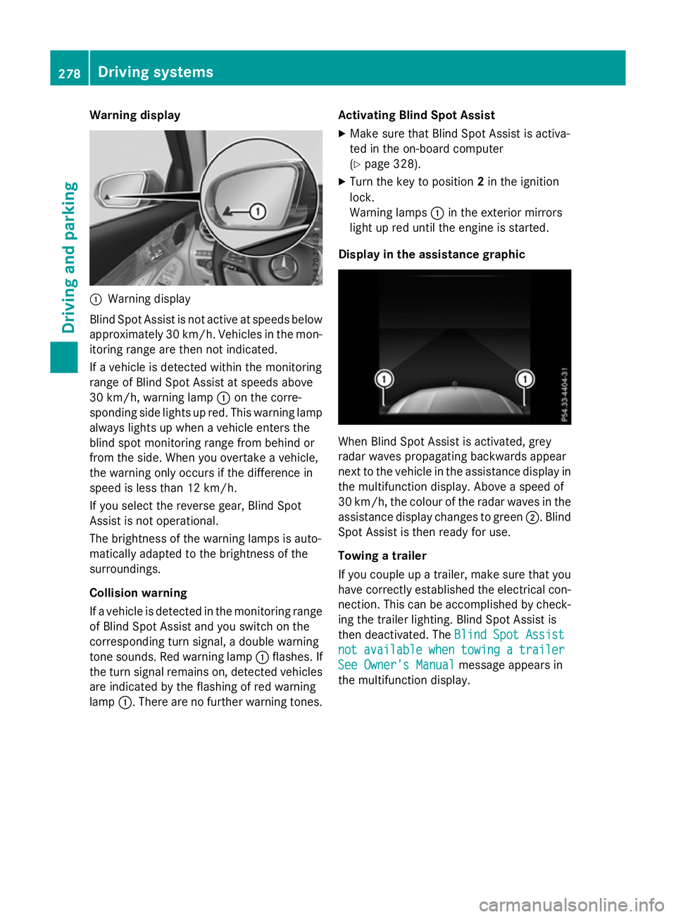
Warning display
:
Warning display
Blind Spot Assist is not active at speeds below approximately 30 km/h. Vehicles in the mon-itoring range are then not indicated.
If a vehicle is detected within the monitoring
range of Blind Spot Assist at speeds above
30 km/h, warning lamp :on the corre-
sponding side lights up red. This warning lamp
always lights up when a vehicle enters the
blind spot monitoring range from behind or
from the side. When you overtake a vehicle,
the warning only occurs if the difference in
speed is less than 12 km/h.
If you select the reverse gear, Blind Spot
Assist is not operational.
The brightness of the warning lamps is auto-
matically adapted to the brightness of the
surroundings.
Collision warning
If a vehicle is detected in the monitoring range
of Blind Spot Assist and you switch on the
corresponding turn signal, a double warning
tone sounds. Red warning lamp :flashes. If
the turn signal remains on, detected vehicles
are indicated by the flashing of red warning
lamp :. There are no further warning tones. Activating Blind Spot Assist
X Make sure that Blind Spot Assist is activa-
ted in the on-board computer
(Y page 328).
X Turn the key to position 2in the ignition
lock.
Warning lamps :in the exterior mirrors
light up red until the engine is started.
Display in the assistance graphic When Blind Spot Assist is activated, grey
radar waves propagating backwards appear
next to the vehicle in the assistance display in the multifunction display. Above a speed of
30 km/h, the colour of the radar waves in the
assistance display changes to green ;. Blind
Spot Assist is then ready for use.
Towing a trailer
If you couple up a trailer, make sure that you
have correctly established the electrical con- nection. This can be accomplished by check-ing the trailer lighting. Blind Spot Assist is
then deactivated. The Blind Spot Assist Blind Spot Assist
not
not available
available when
whentowing
towing a
atrailer
trailer
See Owner's Manual
See Owner's Manual message appears in
the multifunction display. 278
Driving systemsDriving and parking
Page 286 of 497
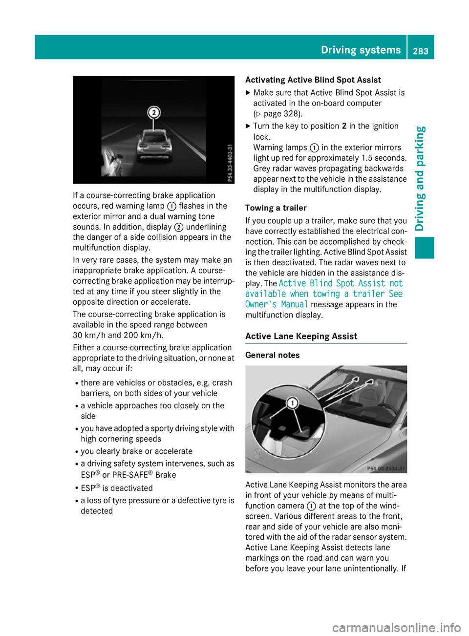
If a course-correcting brake application
occurs, red warning lamp :flashes in the
exterior mirror and a dual warning tone
sounds. In addition, display ;underlining
the danger of a side collision appears in the
multifunction display.
In very rare cases, the system may make an
inappropriate brake application. A course-
correcting brake application may be interrup-
ted at any time if you steer slightly in the
opposite direction or accelerate.
The course-correcting brake application is
available in the speed range between
30 km/h and 200 km/h.
Either a course-correcting brake application
appropriate to the driving situation, or none at all, may occur if:
R there are vehicles or obstacles, e.g. crash
barriers, on both sides of your vehicle
R a vehicle approaches too closely on the
side
R you have adopted a sporty driving style with
high cornering speeds
R you clearly brake or accelerate
R a driving safety system intervenes, such as
ESP ®
or PRE-SAFE ®
Brake
R ESP ®
is deactivated
R a loss of tyre pressure or a defective tyre is
detected Activating Active Blind Spot Assist
X Make sure that Active Blind Spot Assist is
activated in the on-board computer
(Y page 328).
X Turn the key to position 2in the ignition
lock.
Warning lamps :in the exterior mirrors
light up red for approximately 1.5 seconds. Grey radar waves propagating backwards
appear next to the vehicle in the assistance
display in the multifunction display.
Towing a trailer
If you couple up a trailer, make sure that you have correctly established the electrical con-
nection. This can be accomplished by check- ing the trailer lighting. Active Blind Spot Assist
is then deactivated. The radar waves next to
the vehicle are hidden in the assistance dis-
play. The Active
Active Blind BlindSpot
SpotAssist
Assist not
not
available
available when
whentowing
towing a
atrailer
trailer See
See
Owner's Manual
Owner's Manual message appears in the
multifunction display.
Active Lane Keeping Assist General notes
Active Lane Keeping Assist monitors the area
in front of your vehicle by means of multi-
function camera :at the top of the wind-
screen. Various different areas to the front,
rear and side of your vehicle are also moni-
tored with the aid of the radar sensor system. Active Lane Keeping Assist detects lane
markings on the road and can warn you
before you leave your lane unintentionally. If Driving systems
283Driving and parking Z
Page 295 of 497
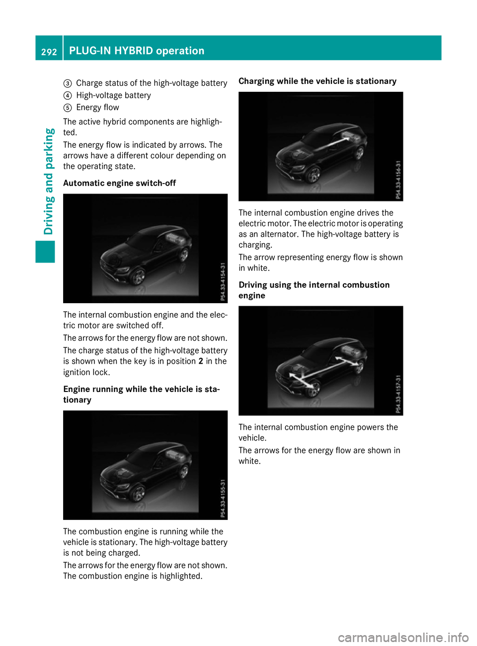
=
Charge status of the high-voltage battery
? High-voltage battery
A Energy flow
The active hybrid components are highligh-
ted.
The energy flow is indicated by arrows. The
arrows have a different colour depending on
the operating state.
Automatic engine switch-off The internal combustion engine and the elec-
tric motor are switched off.
The arrows for the energy flow are not shown.
The charge status of the high-voltage battery
is shown when the key is in position 2in the
ignition lock.
Engine running while the vehicle is sta-
tionary The combustion engine is running while the
vehicle is stationary. The high-voltage battery
is not being charged.
The arrows for the energy flow are not shown. The combustion engine is highlighted. Charging while the vehicle is stationary
The internal combustion engine drives the
electric motor. The electric motor is operating
as an alternator. The high-voltage battery is
charging.
The arrow representing energy flow is shown in white.
Driving using the internal combustion
engine The internal combustion engine powers the
vehicle.
The arrows for the energy flow are shown in
white. 292
PLUG
‑IN HYBRID operationDriving and pa rking