Page 209 of 246
 Owners Manual Jump-starting
Introduction
This chapter contains information on the following subjects:
Jump-starting using the battery from another vehicle
207
Jump-starting in vehicles with the START-STOP system")
Jump-starting
Introduction
This chapter contains information on the following subjects:
Jump-starting using the battery from another vehicle
207
Jump-starting in vehicles with the START-STOP system
208
Jump-starting vehicles with the vehicle battery in the boot
208WARNING■ A discharged vehicle battery may already freeze at temperatures just be-
low 0 °C. If the battery is frozen, do not jump start with the battery of an-
other vehicle – there is a risk of explosion.■
Pay attention to the warning instructions relating to working in the en-
gine compartment » page 182.
■
The non-insulated parts of the terminal clamps must never touch each
other – there is a risk of short circuit.
■
The jump-start cable connected to the positive terminal of the battery
must not come into contact with electrically conducting parts of the vehicle
– there is a risk of short circuit.
■
Do not clamp the jump-start cable to the negative terminal of the dis-
charged battery. There is the risk of detonating gas seeping out the battery
being ignited by the strong spark which results from the engine being star-
ted.
■
Route the jump-start cables so that they cannot be caught by any rotat-
ing parts in the engine compartment.
■
Do not bend over the battery – there is a risk of caustic burns.
■
The vent screws of the battery cells must be tightened firmly.
■
Keep any sources of ignition (naked flame, smouldering cigarettes, etc.)
away from the battery – risk of explosion!
■
Never jump-start vehicle batteries with insufficient acid levels – risk of
explosion and chemical burns.
CAUTION
■ There must not be any contact between the two vehicles otherwise current
may flow as soon as the negative terminals are connected.■
The discharged battery must be properly connected to the system of the ve-
hicle.
■
We recommend you buy jump-start cables from a car battery specialist.
Jump-starting using the battery from another vehicleFig. 182
Jump-starting: A – flat battery, B
– battery providing current
Read and observe and on page 207 first.
The battery of another vehicle can be used to jump-start your vehicle if the en-
gine will not start because the battery is flat. Jump-start cables are required for
this purpose.
The jump-start cables must be attached in the following sequence.
›
Attach clamp
1
to the positive terminal of the discharged battery
A
» Fig. 182 .
›
Attach clamp
2
to the positive terminal of the battery supplying power
B
.
›
Attach clamp
3
to the negative terminal of the battery supplying power
B
.
›
Attach the clamp
4
to a solid metal component firmly connected to the en-
gine block or to the engine block itself.
Starting engine
›
Start the engine on the vehicle providing the power and allow it to idle.
›
Start the engine of the vehicle with the discharged battery.
›
If the engine does not start, halt the attempt to start the engine after 10 sec-
onds and wait for 30 seconds before repeating the process.
›
Disconnect the cables in exactly the reverse order to the one described
above.
Both batteries must have a rated voltage of 12 V. The capacity (Ah) of the bat-
tery supplying the power must not be significantly less than the capacity of
the discharged battery in your vehicle.
Jump-start cables
Only use jump-start cables which have an adequately large cross-section and
insulated terminal clamps. Observe the instructions of the jumper lead manu-
facturer.
Positive cable - colour coding in the majority of cases is red.
207Emergency equipment and self-help
Page 210 of 246
 Owners Manual Negative cable - colour coding in the majority of cases is black.
Jump-starting in vehicles with the START-STOP system
Fig. 183
Engine earth: START-STOP sys-
tem
Read and observe and on page 207 fi")
Negative cable - colour coding in the majority of cases is black.
Jump-starting in vehicles with the START-STOP system
Fig. 183
Engine earth: START-STOP sys-
tem
Read and observe and on page 207 first.
On vehicles with the START-STOP system, the jump-start cable of the charger
must never be connected directly to the negative pole of the vehicle battery,
but only to the engine earth » Fig. 183.
Jump-starting vehicles with the vehicle battery in the boot
Fig. 184
Detail of the engine compart-
ment: Jump-starting point
Read and observe and on page 207 first.
On vehicles with the vehicle battery in the boot, the positive terminal of the
battery supplying the power can only be connected to the jump-starting point
in the engine compartment of the vehicle being started by means of a jump-
start cable » Fig. 184.
›
Open the protective cap of the jump-starting point in the direction of the ar-
row » Fig. 184 .
›
Connect the positive terminal of the battery supplying the power with the
jump-starting point.
› Attach the negative terminal of the battery supplying the power to a solid
metal part firmly connected to the engine block or to the engine block itself.›
Start the engine.
›
After starting the engine, close the protective cap of the jump-starting point.
Towing the vehicle
Introduction
This chapter contains information on the following subjects:
Front towing eye
209
Rear towing eye
210
Vehicles with a tow hitch
210
Vehicles with manual transmission may be towed in with a tow bar or a tow
rope or with the front or rear wheels raised.
Vehicles with automatic transmission may be towed in with a tow bar or a tow
rope or with the front wheels raised. If the vehicle is raised at rear, the auto-
matic gearbox is damaged!
A tow bar is the safest way of towing a vehicle and also minimises any shocks.
Only use a tow rope if a suitable tow bar is not available.
When towing, the following guidelines must be observed.
Driver of the tow vehicle
›
Release the clutch particularly gently when starting off or depress the accel-
erator particularly gently if the vehicle is fitted with an automatic gearbox.
›
On vehicles with a manual transmission, only push down on the accelerator
pedal once the rope is taught.
The maximum towing speed is 50 km/h.
Driver of the towed vehicle
›
Switch on the ignition so that the steering wheel is not locked and so that
the turn signal lights, horn, windscreen wipers and windscreen washer sys-
tem can be used.
›
Take the vehicle out of gear or move the selector lever into position N if the
vehicle is fitted with an automatic gearbox.
Please note that the brake servo unit and power steering only operate if the
engine is running. If the engine is not running, significantly more physical force
is required to depress the brake pedal and steer the vehicle.
208Do-it-yourself
Page 211 of 246
 Owners Manual If using a tow rope, ensure that it is always kept taught.
CAUTION
■Do not tow start the engine – there is a risk of damaging the engine and the
catalytic converter. The battery from another vehic")
If using a tow rope, ensure that it is always kept taught.
CAUTION
■Do not tow start the engine – there is a risk of damaging the engine and the
catalytic converter. The battery from another vehicle can be used as a jump-
start aid » page 207 , Jump-starting .■
If the gearbox no longer contains any oil because of a defect, your vehicle
must only be towed with the driven wheels raised clear of the ground or on a
special breakdown vehicle or trailer.
■
The vehicle must be transported on a special breakdown vehicle or trailer if it
is not possible to tow in the vehicle in the way described or if the towing dis-
tance is greater than 50 km.
■
To protect both vehicles when tow-starting or towing, the tow rope should
be elastic. Thus one should only use plastic fibre rope or a rope made out of a
similarly elastic material.
■
While towing, take care to avoid impermissibly high tensile forces or jerky
loads. There is always a risk of excessive stresses and damage resulting at the
points to which you attach the tow rope or tow bar when you attempt to tow a
vehicle which is not standing on a paved road.
■
Attach the tow rope or the tow bar to the towing eyes » page 209 , Front
towing eye or » page 210 , Rear towing eye to the detachable ball head of the
towing equipment » page 163 .
Note
■
We recommend using a tow rope from ŠKODA Original Accessories, which is
available from a ŠKODA Partner.■
Towing another vehicle requires a certain amount of practice. Both drivers
should be familiar with the particular points about towing a vehicle. Unskilled
drivers should not attempt to tow in another vehicle or to be towed in.
■
When towing, respect the national legal provisions, especially those which
relate to the identification of the towing vehicle and the vehicle being towed.
■
The tow rope must not be twisted as it may in certain circumstances result in
the front towing eye being unscrewed out of your vehicle.
Front towing eyeFig. 185
Removing the cap / installing the towing eye
Read and observe
on page 209 first.
›
Remove the cap from the front bumper » Fig. 185 -
.
›
Screw in the towing eye by turning to the left up to the stop
» Fig. 185 -
and tighten as much as possible. For tightening purposes, we recommend,
for example, using the wheel wrench, towing eye from another vehicle or a
similar object that can be pushed through the eye.
›
After unscrewing the towing eye, put the cap on and press into place. The
cap must engage firmly.
CAUTION
The towing eye must always be screwed in fully and firmly tightened, other-
wise the towing eye can tear when towing in or tow-starting.209Emergency equipment and self-help
Page 212 of 246
 Owners Manual Rear towing eyeFig. 186
Removing the cap / installing the towing eye
Read and observe
on page 209 first.
›
Press onto the bottom part of the cap in the rear bumper » Fig. 186 -
and
remove")
Rear towing eyeFig. 186
Removing the cap / installing the towing eye
Read and observe
on page 209 first.
›
Press onto the bottom part of the cap in the rear bumper » Fig. 186 -
and
remove it.
›
Screw in the towing eye by turning to the left up to the stop » Fig. 186 -
and tighten as much as possible. For tightening purposes, we recommend,
for example, using the wheel wrench, towing eye from another vehicle or a
similar object that can be pushed through the eye.
›
After unscrewing the towing eye, put the cap on and press into place. The
cap must engage firmly.
On vehicles with a factory-fitted towing device, there is no mount for the
screw-in towing eye behind the cap » page 210, Vehicles with a tow hitch .
CAUTION
The towing eye must always be screwed in fully and firmly tightened, other-
wise the towing eye can tear when towing in or tow-starting.
Vehicles with a tow hitch
Read and observe
on page 209 first.
On vehicles with a factory-fitted towing device, there is no mount for the
screw-in towing eye behind the cap.
Use the built-in detachable ball rod for towing » page 163, Towing device .
Towing the vehicle using the towing device is a viable alternative solution to
using the towing eye.
If the towing device is removed completely, it must be replaced with the
standard reinforcement of the rear bumper which is part of the mount for the
towing eye.
If this procedure is not observed, the vehicle may not meet the national legal
provisions.
CAUTION
The detachable ball rod and/or the vehicle can be damaged if an unsuitable
tow bar is used.
Note
The detachable ball rod must always be in the vehicle so that it can be used for
towing, if necessary.
Radio remote control
Introduction
This chapter contains information on the following subjects:
Replacing the battery in the remote control key
211
Synchronising the remote control
211
Replace the battery in the remote control of the auxiliary heater (parking
heater)
211
CAUTION
■ The replacement battery must have the same specification as the original
battery.■
We recommend having faulty rechargeable batteries replaced by a ŠKODA
service partner.
■
When replacing the battery, pay attention to the correct polarity.
For the sake of the environment
Dispose of the used battery in accordance with national legal provisions.210Do-it-yourself
Page 213 of 246
 Owners Manual Replacing the battery in the remote control keyFig. 187
Remove cover/take out battery
Read and observe
on page 210 first.
The battery is located under a cover
A
» Fig. 187 .
We recommend having")
Replacing the battery in the remote control keyFig. 187
Remove cover/take out battery
Read and observe
on page 210 first.
The battery is located under a cover
A
» Fig. 187 .
We recommend having the key batteries replaced by a specialist garage. How-
ever, if you would like to replace the discharged battery yourself proceed as
follows.
›
Flip out the key.
›
Press off the battery cover with your thumb or using a flat screwdriver in the
region of the arrows
1
.
›
Remove the discharged battery from the key by pressing the battery down in
the region of the arrow
2
.
›
Insert the new battery.
›
Place the battery cover on the key and press it down until it clicks into place.
Note
■ The key has to be synchronised if the vehicle cannot be unlocked or locked
with the remote control key after replacing the battery » page 211.■
If a key has an affixed decorative cover, this will be destroyed when the bat-
tery is replaced. A replacement cover can be purchased from a ŠKODA Partner.
Synchronising the remote control
Read and observe
on page 210 first.
If the vehicle does not unlock when pressing the remote control, the key may
not be synchronised. This can occur when the buttons on the remote control
key are actuated a number of times outside of the operative range of the
equipment or the battery in the remote control key was replaced.
Synchronise the key as follows.
›
Press any button on the remote control key.
›
Pressing of the button means that the door will unlock with the key within 1
minute.
Replace the battery in the remote control of the auxiliary heater
(parking heater)
Fig. 188
Radio remote control: Battery
cover
Read and observe on page 210 first.
The battery is located under a cover on the back of the radio remote con-
trol » Fig. 188 .
›
Insert a flat, blunt object, such as a coin, into the gap of the battery cover.
›
Turn the cover against the direction of the arrow up to the mark to open the
cover.
›
Replace the battery.
›
Return the battery cover.
›
Turn the cover in the direction of the arrow up to the initial marking, engage.
211Emergency equipment and self-help
Page 214 of 246
 Owners Manual Emergency unlocking/locking
Introduction
This chapter contains information on the following subjects:
Unlocking/locking the drivers door
212
Locking a door
212
Unlocking the tailgate
212
Selector")
Emergency unlocking/locking
Introduction
This chapter contains information on the following subjects:
Unlocking/locking the driver's door
212
Locking a door
212
Unlocking the tailgate
212
Selector lever-emergency unlocking
213
Unlocking/locking the driver's door
Fig. 189
Handle on the driver's door: cov-
ered locking cylinder
›
Pull on the handle.
›
Push the vehicle key into the recess on the bottom side of the cover in the
region of the arrow and fold it upwards » Fig. 189.
›
Insert the vehicle key (the buttons facing upward) into the locking cylinder
and lock/unlock the vehicle.
CAUTION
Make sure you do not damage the paint when performing an emergency lock-
ing/unlocking.Locking a doorFig. 190
Left rear door: Emergency lock-
ing
An emergency locking mechanism is located on the face side of the doors
which have no locking cylinder, it is only visible after opening the door.
›
Remove the cover
A
» Fig. 190 .
›
Insert the key into the slot
B
and turn it into the horizontal position in the
direction of the arrow (mirror-inverted on the right doors).
›
Replace the cover.
After closing the door, it cannot be opened from the outside. The door is un-
locked by pulling on the door opening lever and is then opened from the out-
side.
Unlocking the tailgate
Fig. 191
Emergency unlocking: Superb / Superb Combi
Unlocking (Superb)
›
Fold the rear seat backrest forward » page 85, Seat backrests .
›
Insert the vehicle key into the slot in the trim panel as far as the
stop » Fig. 191 -
.
212Do-it-yourself
Page 215 of 246
 Owners Manual ›Unlock the lid by moving it in the direction of the arrow.›Open the tailgate.
Unlocking (Superb Combi)›
Fold the rear seat backrest forward » page 85, Seat backrests .
›
Insert a screwdrive")
›Unlock the lid by moving it in the direction of the arrow.›Open the tailgate.
Unlocking (Superb Combi)›
Fold the rear seat backrest forward » page 85, Seat backrests .
›
Insert a screwdriver or similar tool into the opening of the trim as far as it
goes » Fig. 191 -
.
›
Unlock the lid by moving it in the direction of the arrow.
›
Open the tailgate.
Selector lever-emergency unlocking
Fig. 192
Selector lever-emergency unlocking
›
Firmly apply the handbrake.
›
Grasp the cover
1
in the area of arrow
2
» Fig. 192 and carefully pull up-
wards.
›
Also unlock the cover on the other side.
›
Use a finger to press the yellow plastic part in the direction of the arrow
3
.
›
At the same time, press the locking button in the selector lever and move the selector lever to position N.
If the selector lever is moved again to position P, it is once again blocked.
Emergency operation of the sliding/tilting roof
Introduction
This chapter contains information on the following subjects:
Operation
213
Activation after un-clamping and re-clamping the battery
214
Operation
Fig. 193
Point for positioning screwdriver/opening for positioning the key
The sliding/tilting roof can be closed or opened manually if a fault occurs. The
emergency operation of the sliding/tilting roof is located underneath the
glasses storage box
1
» page 91 , Glasses storage box .
›
Open the glasses storage box.
›
Carefully insert an approximately 5 mm wide screwdriver into the slot in the
positions shown by the arrows
1
» Fig. 193 .
›
Carefully fold the glasses storage box downwards by gently pressing down
and turning the screwdriver.
›
Insert an Allen key, SW 4, up to the stop into the opening
2
and close or
open the sliding/tilting roof.
›
Reinstall the glasses storage box by first inserting the plastic plugs and then
pushing the entire part upwards.
Have the fault on the sliding tilting roof rectified as soon as possible by a spe- cialist garage.
213Emergency equipment and self-help
Page 216 of 246
 Owners Manual Note■It is necessary after each emergency operation to move the sliding/tilting
roof into the basic position. 1)
This is why the rotary switch must be set to posi-
tion A
» Fig. 45 on page 62")
Note■It is necessary after each emergency operation to move the sliding/tilting
roof into the basic position. 1)
This is why the rotary switch must be set to posi-
tion A
» Fig. 45 on page 62 and pressed forwards for about 10 seconds.
■
After each emergency operation, it is necessary to activate the
roof 2)
» page 214 .
Activation after un-clamping and re-clamping the battery
The panoramic sliding/tilting roof (referred to form now on as just the sliding/
tiling roof) and the sun screen must be activated after disconnecting and re-
connecting the battery.
To activate the sliding/tilting roof, press the notch on the control dial down-
wards and forwards for approx. 10 seconds.
To activate the sun screen, press and hold the switch
G
» Fig. 47 on
page 64 for approx. 10 seconds.
If the sliding/tilting roof or sun screen is not fully closed or pushed shut when
disconnecting and reconnecting the battery, they must first be closed or push-
ed shut » page 64 , Opening/closing the sun screen » page 64 , Operation . Only
then is it possible to perform the activation.
Replacing windscreen wiper blades
Introduction
This chapter contains information on the following subjects:
Replacing the windscreen wiper blades
214
Replacing the rear window wiper blade
215WARNINGReplace the windscreen wiper blades once or twice a year for safety rea-
sons. These can be purchased from a ŠKODA Partner.Replacing the windscreen wiper bladesFig. 194
Windscreen wiper blade
Read and observe on page 214 first.
Before replacing the windscreen wiper blade, put the windscreen wiper arms
into the service position.
Service position for changing wiper blades
›
Closing the bonnet.
›
Switch the ignition off and on again.
›
Within 10 seconds, press the lever in position
4
and hold it for around 2 sec-
onds » Fig. 62 on page 76 .
The windscreen wiper arms move into the service position.
Removing the wiper blade
›
Lift the windscreen wiper arm away from the windscreen.
›
Hold the upper part of the wiper arm and unlock the securing mechanism
1
» Fig. 194 .
›
Remove the wiper blade in the direction of the arrow
2
.
Fitting the wiper blade
›
Push the wiper blade in until it latches on the stop.
›
Check that the wiper blade is correctly attached.
›
Fold the wiper arm back to the windscreen.
›
Turn on the ignition and press the lever into position
4
» Fig. 62 on page 76 .
The windscreen wiper arms move into the home position.
1)
Applies to emergency operation of the Superb sliding/tilting roof.
2)
Applies to emergency operation of the Superb Combi sliding/tilting roof.
214Do-it-yourself
 1
1 2
2 3
3 4
4 5
5 6
6 7
7 8
8 9
9 10
10 11
11 12
12 13
13 14
14 15
15 16
16 17
17 18
18 19
19 20
20 21
21 22
22 23
23 24
24 25
25 26
26 27
27 28
28 29
29 30
30 31
31 32
32 33
33 34
34 35
35 36
36 37
37 38
38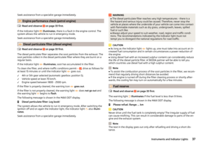 39
39 40
40 41
41 42
42 43
43 44
44 45
45 46
46 47
47 48
48 49
49 50
50 51
51 52
52 53
53 54
54 55
55 56
56 57
57 58
58 59
59 60
60 61
61 62
62 63
63 64
64 65
65 66
66 67
67 68
68 69
69 70
70 71
71 72
72 73
73 74
74 75
75 76
76 77
77 78
78 79
79 80
80 81
81 82
82 83
83 84
84 85
85 86
86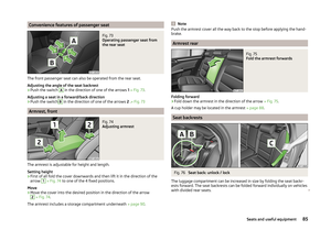 87
87 88
88 89
89 90
90 91
91 92
92 93
93 94
94 95
95 96
96 97
97 98
98 99
99 100
100 101
101 102
102 103
103 104
104 105
105 106
106 107
107 108
108 109
109 110
110 111
111 112
112 113
113 114
114 115
115 116
116 117
117 118
118 119
119 120
120 121
121 122
122 123
123 124
124 125
125 126
126 127
127 128
128 129
129 130
130 131
131 132
132 133
133 134
134 135
135 136
136 137
137 138
138 139
139 140
140 141
141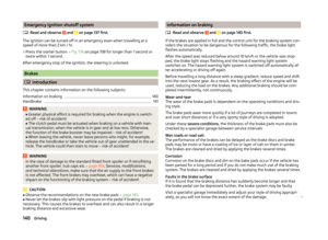 142
142 143
143 144
144 145
145 146
146 147
147 148
148 149
149 150
150 151
151 152
152 153
153 154
154 155
155 156
156 157
157 158
158 159
159 160
160 161
161 162
162 163
163 164
164 165
165 166
166 167
167 168
168 169
169 170
170 171
171 172
172 173
173 174
174 175
175 176
176 177
177 178
178 179
179 180
180 181
181 182
182 183
183 184
184 185
185 186
186 187
187 188
188 189
189 190
190 191
191 192
192 193
193 194
194 195
195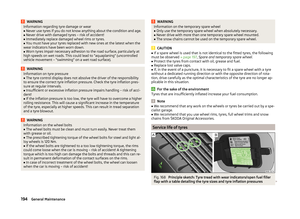 196
196 197
197 198
198 199
199 200
200 201
201 202
202 203
203 204
204 205
205 206
206 207
207 208
208 209
209 210
210 211
211 212
212 213
213 214
214 215
215 216
216 217
217 218
218 219
219 220
220 221
221 222
222 223
223 224
224 225
225 226
226 227
227 228
228 229
229 230
230 231
231 232
232 233
233 234
234 235
235 236
236 237
237 238
238 239
239 240
240 241
241 242
242 243
243 244
244 245
245