Page 105 of 246
 Owners Manual WARNINGEnsure that the carrier rails and variable loading floor are correctly fastened
when installing the variable loading floor. If this is not the case, there is a
risk of injury for the occupants.")
WARNINGEnsure that the carrier rails and variable loading floor are correctly fastened
when installing the variable loading floor. If this is not the case, there is a
risk of injury for the occupants.
Extending variable loading floor with integrated aluminium rails
and faseting elements (Superb Combi)
Introduction
This chapter contains information on the following subjects:
Partial extension of variable load floor
103
Divide boot
103
Fit and remove variable loading floor
104
Fixing set
104
Movable lashing eyes
105
The variable loading floor makes handling of bulky items of luggage easier.
CAUTION
The maximum permissible load of the variable loading floor is 75 kg.
Note
The space below the variable loading floor can be used for stowing objects, for
example the fastening elements, removed foldable boot cover, etc.
Partial extension of variable load floor
Fig. 112
Boot: partially pulling out the variable loading floor
Read and observe on page 103 first.
The variable loading floor can be partially pulled out over the rear bumper.
›
Grasp the rear of the variable loading floor by the handle and lift gently in the
direction of the arrow
1
» Fig. 112 .
›
Extend the variable load floor over the bumper in the direction of the arrow
2
until it engages in the opening
C
.
The variable loading floor which is pulled out in such a way is solely used as a
seat, for example for changing shoes.
›
To push in the rear section of the variable loading floor, grasp by the handle
and lift slightly in the direction of the arrow
1
.
›
Slide the variable load floor forward up to the stop.
When pulling out the variable loading floor, the front edge (close to the rear
seats) is lifted at the same time. Thus, small objects can no longer fall into the
space between the boot floor and the variable loading floor.
CAUTION
Ensure that the raised front edge of the variable loading floor is not damaged.
Divide boot
Fig. 113
Dividing the boot
Read and observe on page 103 first.
The boot can be divided with the variable loading floor.
›
Grasp the rear of the variable loading floor by the handle and lift in the direc-
tion of the arrow
1
» Fig. 112 on page 103 .
›
Insert the trailing edge in one of the openings
A
» Fig. 113 .
The variable loading floor is secured in the openings
A
against movement.
103Seats and useful equipment
Page 106 of 246
 Owners Manual The variable loading floor can be pulled out a little more before dividing the
boot with the variable loading floor » page 103. This enlarges the space be-
tween the rear seats and the separation.
C")
The variable loading floor can be pulled out a little more before dividing the
boot with the variable loading floor » page 103. This enlarges the space be-
tween the rear seats and the separation.
CAUTION
Ensure that the raised front edge of the variable loading floor is not damaged.
Fit and remove variable loading floor
Fig. 114
Boot: Fold up variable loading floor
Fig. 115
Boot: remove variable loading floor
Read and observe
on page 103 first.
The variable loading floor can be removed and reinstalled, if necessary.
Removing
›
Grasp the rear part of the floor by the handle, raise it slightly in the direction
of the arrow
1
» Fig. 114 and pull it out over the bumper in the direction of
the arrow
2
until it engages in the opening
C
» Fig. 115 .
›Fold up the loading floor by moving it in the direction of the arrow3» Fig. 114
.›
Press the safety buttons
A
» Fig. 115 and remove the floor.
Fitting
›
Fold up the floor and place it on the carrier rails.
›
Push the floor forwards until it engages in the openings
B
in the carrier
rails » Fig. 115 .
›
Carefully press in the vicinity of the openings
C
on the floor until it clicks in-
to place, if necessary press the safety buttons
A
.
WARNINGEnsure the variable loading floor is attached correctly during installation. If
this is not the case, there is a risk of injury for the occupants.
Fixing set
Fig. 116
Telescopic pole and tensioning strap
Read and observe
on page 103 first.
The fixing set can be used for dividing the boot or for securing the objects
which are being transported.
Telescopic pole
›
Insert the holders for the telescopic pole into the left and right openings of
the carrier rails.
›
Press the top part of the holder in the direction of the arrow
1
» Fig. 116 and
simultaneously push in the desired position in the direction of the arrow
2
.
›
Ensure that the holder is correctly locked in place.
104Operation
Page 107 of 246
 Owners Manual Tensioning strap›Insert the tensioning strap holders into the opening on the left or right carri-
er rail.›
Press the holder in the direction of the arrow
3
» Fig. 116 and simultaneous-
ly pu")
Tensioning strap›Insert the tensioning strap holders into the opening on the left or right carri-
er rail.›
Press the holder in the direction of the arrow
3
» Fig. 116 and simultaneous-
ly push in the desired position in the direction of the arrow
4
.
›
Ensure that the holder is correctly locked in place.
›
Place the object that is to be secured behind the tensioning strap.
›
Press the button
5
on the top side of the holder and tighten the strap.
WARNINGThe objects in the boot must be firmly secured with the fixing set so that
they cannot move freely and uncontrollably and to prevent damage to ob-
jects or injuries to occupants.
Note
■ Do not use the fixing set to secure objects that might damage the fixing set.■The tensioning strap can also be fully reeled up by pressing the button5
» Fig. 116 .
Movable lashing eyes
Fig. 117
Moveable lashing eyes
Read and observe on page 103 first.
There are four moveable lashing eyes in the boot that can, for example, be
used to attach the fixing nets.
›
Press the button
1
» Fig. 117 and push the lashing eye in the desired posi-
tion in the direction of the arrow
2
.
›
Fold up the clamp
3
» Fig. 117 and, for example, attach the fixing net.
Net partition (Superb Combi)
Introduction
This chapter contains information on the following subjects:
Using the net partition behind the rear seats
105
Using the net partition behind the front seats
106
Removing and refitting the net partition housing
106WARNING■ Make sure that the transverse rod is inserted into the mountsC » Fig. 118 on page 105 or » Fig. 119 on page 106 in the forward position.■
The belt locks and the belts must be in their original position after folding
back the seat cushions and backrests - they must be ready to use.
■
The seat backrests must be securely locked in position so that no objects
in the luggage compartment can slide into the passenger compartment on
sudden braking – risk of injury.
■
Ensure that the rear seat backrests are properly engaged. Only then can
the seat belt for the middle seat reliably fulfil its function.
Using the net partition behind the rear seats
Fig. 118
Net partition behind the front
seats in the pulled-out state
Read and observe on page 105 first.
Extending
›
Pull the net partition by the tab
A
» Fig. 118 in the direction of the fasteners
C
.
›
Insert the cross rod into one of the mounts
C
and push forwards.
›
Insert the transverse rod into the mount
C
on the other side of the vehicle
in the same way.
105Seats and useful equipment
Page 108 of 246
 Owners Manual Retracting›Pull the transverse rod back slightly first on one side and then on the other
and remove it from the mounts C
» Fig. 118 .
›
Hold the cross rod in such a way that the net partition c")
Retracting›Pull the transverse rod back slightly first on one side and then on the other
and remove it from the mounts C
» Fig. 118 .
›
Hold the cross rod in such a way that the net partition can slowly roll up into
the housing
B
without being damaged.
Note
If you wish to use the entire luggage compartment, the roll-up luggage com-
partment cover can be removed » page 99.
Using the net partition behind the front seats
Fig. 119
Net partition behind the front
seats in the pulled-out state
Read and observe on page 105 first.
Extending
›
Fold the rear seats forward » page 85.
›
Pull the net partition by the tab
A
» Fig. 119 .
›
First of all insert the cross rod into the mount
C
on one side and push it for-
ward.
›
Insert the transverse rod into the mount
C
on the other side of the vehicle
in the same way.
Retracting
›
Pull the transverse rod back slightly first on one side and then on the other
and remove it from the mounts
C
» Fig. 119 .
›
Hold the cross rod in such a way that the net partition can slowly roll up into
the housing
B
without being damaged.
›
Fold the rear seats back into their original positions » page 85.
Removing and refitting the net partition housingFig. 120
Rear seats: Removing the net
partition housing
Read and observe on page 105 first.
Removing
›
Fold the rear seats forward » page 85.
›
Open the rear right door.
›
Push the housing
A
in the direction of the arrow
1
and remove it from the
mounts on the right seat backrests in the direction of the arrow
2
» Fig. 120 .
Fitting
›
Insert the recesses on the housing
A
» Fig. 120 into the mounts on the rear
seat backrests.
›
Push the net partition housing in the opposite direction of the arrow
1
as
far as the stop.
›
Fold the rear seats back into their original positions » page 85.
Roof rack system
Introduction
This chapter contains information on the following subjects:
Attachment points
107
Roof load
107WARNING■ The transported items on the roof rack must be securely attached – risk
of accident!■
Always secure the load with appropriate and undamaged lashing straps
or tensioning straps.
106Operation
Page 109 of 246
 Owners Manual WARNING (Continued)■Distribute the load evenly over the roof rack system.■When transporting heavy objects or objects which take up a large area on
the roof rack system, the handling of the car may")
WARNING (Continued)■Distribute the load evenly over the roof rack system.■When transporting heavy objects or objects which take up a large area on
the roof rack system, the handling of the car may change as a result of the
displacement of the centre of gravity. The style of driving and speed must
therefore be adapted to the current circumstances.■
Avoid abrupt and sudden driving/braking manoeuvres.
■
Adjust the speed and driving style to the visibility, weather, road and traf-
fic conditions.
■
The permissible roof load, permissible axle loads and permissible total ve-
hicle weight must not be exceeded under any circumstances – risk of acci-
dent!
CAUTION
■ Only roof racks from the ŠKODA Original Accessories range should be used.■When dealing with roof racks, the installation instructions supplied with the
roof luggage rack system must be observed.■
On models fitted with a power sliding/tilting roof or a panoramic sliding roof,
ensure that the opened sliding/tilting roof or the panoramic sliding roof does
not strike any items of luggage transported on the roof.
■
Ensure that the boot lid does not hit the roof load when opened.
■
The height of the vehicle changes after mounting a roof luggage rack system
and the load that is secured to it. Compare the vehicle height with available
clearances, such as underpasses and garage doors.
■
Always remove the roof luggage rack system before entering an automated
car wash.
■
Ensure the roof aerial is not impaired by the secured load.
For the sake of the environment
The increased aerodynamic drag results in a higher fuel consumption.Attachment points
Does not apply to the Superb Combi.Fig. 121
Attachment points for roof bars
Read and observe
and on page 106 first.
Installation position of the attachment points for roof bars » Fig. 121:
Forward attachment point
Rear attachment point
Perform the assembly and disassembly according to the enclosed instructions.
CAUTION
Observe the information regarding the assembly and disassembly in the en-
closed instructions.
Roof load
Read and observe
and on page 106 first.
The maximum permissible roof load (including roof rack system) of 100 kg and
the maximum permissible total weight of the vehicle should not be exceeded.
The full permissible roof load cannot be used if a roof rack system with a lower
load carrying capacity is used. In this case, the roof rack system must only be
loaded up to the maximum weight limit specified in the fitting instructions.
AB107Seats and useful equipment
Page 110 of 246
 Owners Manual Air conditioning system
Heating, ventilation, cooling
Introduction
This chapter contains information on the following subjects:
Air outlets
108
Using the air conditioning system economically
109
Op")
Air conditioning system
Heating, ventilation, cooling
Introduction
This chapter contains information on the following subjects:
Air outlets
108
Using the air conditioning system economically
109
Operational problems
110
The heating effect is dependent upon the coolant temperature, thus full heat
output only occurs when the engine has reached its operating temperature.
If the cooling system is switched on, the temperature and air humidity drops in
the vehicle. The cooling system prevents the windows from misting up during
winter months.
It is possible to briefly activate recirculated air mode to enhance the cooling
effect.
Please refer to the information regarding recirculated air mode for the air-con-
ditioning system » page 112 or for Climatronic » page 115.
WARNINGFor your own safety and that of other road users, ensure that all the win-
dows are free of ice, snow and misting. Please familiarize yourself about
how to correctly operate the heating and ventilation systems, how to de-
mist and defrost the windows, as well as with the cooling mode.
CAUTION
■ The air inlet in front of the windscreen must be free (e.g. of ice, snow or
leaves) to ensure that the heating and cooling system operates properly.■
After switching on the cooling Condensation from the evaporator of the air
conditioning may drip down and form a puddle below the vehicle. This is not a
leak!
Note■ The exhaust air streams out through vents at the rear of the luggage com-
partment.■
We recommend that you do not smoke in the vehicle when the recirculating
air mode is operating since the smoke which is drawn at the evaporator from
the interior of the vehicle forms deposits in the evaporator of the air condition-
ing system. This produces a permanent odour when the air conditioning sys-
tem is operating which can only be eliminated through considerable effort and
expense (replacement of compressor).
Air outlets
Fig. 122
Air vents at the front
108Operation
Page 111 of 246
 Owners Manual Fig. 123
Air vents at the rear
Read and observe
and on page 108 first.
Unwarmed or cooled air will flow out of the opened air outlet vents according
to the setting of control dial and the outside")
Fig. 123
Air vents at the rear
Read and observe
and on page 108 first.
Unwarmed or cooled air will flow out of the opened air outlet vents according
to the setting of control dial and the outside atmospheric conditions.
The direction of airflow can be adjusted using the air outlet vents 2,
3 » Fig. 122 and 5 » Fig. 123 - the outlets can be opened and closed individually.
Set the air flow direction
›
To adjust the height of the air flow, turn the horizontal vanes up or down
with the movable adjuster
A
» Fig. 122 » Fig. 123 .
›
To change the lateral direction of the air flow, turn the vertical fins with the
movable adjuster
A
» Fig. 122 or » Fig. 123 to the left or right.
Setting the amount of airflow
›
Turn the knob
B
» Fig. 122 and » Fig. 123 to position
to fully open the air
outlet.
›
Turn the knob
B
» Fig. 122 and » Fig. 123 to position 0 to close the air outlet.
The knob can be adjusted to any position in between.
An overview of the available settings for adjusting the direction of the air
outletSetting the direction of the air outletActive air outlet vents1, 21, 2, 4, 6 2, 3, 54, 6
Note
Do not cover the air outlet vents with objects of any kind.
Using the air conditioning system economically
Read and observe
and on page 108 first.
The compressor on the air conditioning system uses power from the engine
when in cooling mode which will effect the fuel consumption.
It recommended to open the windows or the doors of a vehicle for which the
interior has been strongly heated through the effect of direct sunlight in order
to allow the heated air to escape.
The cooling system should not be on if the windows are open.
For the sake of the environment
Pollutant emissions are also lower when fuel is being saved » page 146, Eco-
nomical driving and environmental sustainability .109Air conditioning system
Page 112 of 246
 Owners Manual Operational problemsRead and observe
and on page 108 first.
If the cooling system does not operate at outside temperatures higher than +5
°C, there is a problem in the system. The reasons for this")
Operational problemsRead and observe
and on page 108 first.
If the cooling system does not operate at outside temperatures higher than +5
°C, there is a problem in the system. The reasons for this may be.
› One of the fuses has blown. Check the fuse and replace if necessa-
ry » page 215 .
› The cooling system has switched off automatically for a short time because
the coolant temperature of the engine is too hot » page 29.
If you are not able to resolve the operational problem yourself, or if the cooler
output has reduced, switch off the cooling system and seek assistance from a
specialist garage.
Air conditioning system (manual air conditioning system)
Introduction
This chapter contains information on the following subjects:
Control elements
110
adjusting
112
Recirculated air mode
112
The cooling system operates only if the following conditions are met. The cooling system is switched on » page 110.
The engine is running.
The outside temperature is above approx. +2 °C.
The blower switch is switched on (positions 1-4).
Under certain circumstances, air at a temperature of about 5 °C can flow out of
the vents when the cooling system is switched on.
If the desired interior temperature can also be achieved without activating the
cooling system, fresh air mode should be selected.
The cooling system is switched off at a high coolant temperature in order to
provide cooling at a high load of the engine.
CAUTION
Lengthy and uneven distribution of the air flow out of the vents (especially
around the feet) and large differences in temperature, for example, when get-
ting out of the vehicle, can cause susceptible individuals to catch a cold.Note■ We recommend that you have the air conditioning system cleaned by a spe-
cialist garage once every year.■
During operation of the air conditioning, an increase in engine idle speed may
occur under certain circumstances in order to ensure sufficient heating com-
fort.
Control elements
Fig. 124
The air conditioning system: Control elements
Read and observe
on page 110 first.
Functions of the individual controls » Fig. 124 :
Set the temperature (turn to the left to reduce the temperature: turn to
the right to increase temperature)
Set the blower stage (stage 0: Blowers, level 4: the highest blower speed)
Set the direction of the air outlet » page 108
Switch the cooling system on/off
Switching the rear window heater on/off » page 73
Aux. heating on/off » page 116
Switch recirculation on/off » page 112
Control the seat heater on the front left seat » page 83
Control the seat heater on the front right seat » page 83
ABC110Operation
 1
1 2
2 3
3 4
4 5
5 6
6 7
7 8
8 9
9 10
10 11
11 12
12 13
13 14
14 15
15 16
16 17
17 18
18 19
19 20
20 21
21 22
22 23
23 24
24 25
25 26
26 27
27 28
28 29
29 30
30 31
31 32
32 33
33 34
34 35
35 36
36 37
37 38
38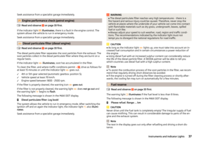 39
39 40
40 41
41 42
42 43
43 44
44 45
45 46
46 47
47 48
48 49
49 50
50 51
51 52
52 53
53 54
54 55
55 56
56 57
57 58
58 59
59 60
60 61
61 62
62 63
63 64
64 65
65 66
66 67
67 68
68 69
69 70
70 71
71 72
72 73
73 74
74 75
75 76
76 77
77 78
78 79
79 80
80 81
81 82
82 83
83 84
84 85
85 86
86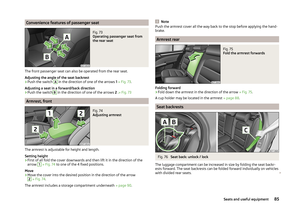 87
87 88
88 89
89 90
90 91
91 92
92 93
93 94
94 95
95 96
96 97
97 98
98 99
99 100
100 101
101 102
102 103
103 104
104 105
105 106
106 107
107 108
108 109
109 110
110 111
111 112
112 113
113 114
114 115
115 116
116 117
117 118
118 119
119 120
120 121
121 122
122 123
123 124
124 125
125 126
126 127
127 128
128 129
129 130
130 131
131 132
132 133
133 134
134 135
135 136
136 137
137 138
138 139
139 140
140 141
141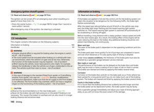 142
142 143
143 144
144 145
145 146
146 147
147 148
148 149
149 150
150 151
151 152
152 153
153 154
154 155
155 156
156 157
157 158
158 159
159 160
160 161
161 162
162 163
163 164
164 165
165 166
166 167
167 168
168 169
169 170
170 171
171 172
172 173
173 174
174 175
175 176
176 177
177 178
178 179
179 180
180 181
181 182
182 183
183 184
184 185
185 186
186 187
187 188
188 189
189 190
190 191
191 192
192 193
193 194
194 195
195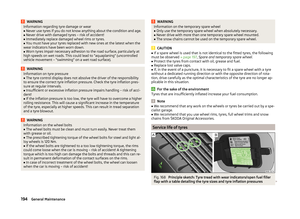 196
196 197
197 198
198 199
199 200
200 201
201 202
202 203
203 204
204 205
205 206
206 207
207 208
208 209
209 210
210 211
211 212
212 213
213 214
214 215
215 216
216 217
217 218
218 219
219 220
220 221
221 222
222 223
223 224
224 225
225 226
226 227
227 228
228 229
229 230
230 231
231 232
232 233
233 234
234 235
235 236
236 237
237 238
238 239
239 240
240 241
241 242
242 243
243 244
244 245
245