Page 161 of 246
 Owners Manual Storing and maintaining speedRead and observe
and on page 158 first.
›
Activate the cruise control system » page 158.
›
Drive at the desired speed.
›
Push the rocker button
B
into the SET")
Storing and maintaining speedRead and observe
and on page 158 first.
›
Activate the cruise control system » page 158.
›
Drive at the desired speed.
›
Push the rocker button
B
into the SET/- » Fig. 150 on page 158 position.
After you have released the rocker button
B
from the SET/- position, the
speed you have just stored is kept constant without having to depress the ac-
celerator.
Changing the stored speed
Read and observe
and on page 158 first.
Increasing the speed with the rocker button
B›
Push the rocker button
B
into the RES/+ » Fig. 150 on page 158 position.
If the rocker button is held in the RES/+ position, the speed will increase con-
tinuously. Release the rocker button once the desired speed is reached. The
set speed is then stored in the memory.
Decreasing the speed using the rocker button
B
The stored speed can be reduced by pushing the rocker switch
B
into the
SET/- » Fig. 150 on page 158 position.
If the rocker button is pressed and held in the SET/- position, the speed will
decrease continuously. Release the rocker button once the desired speed is
reached. The set speed is then stored in the memory.
If the rocker button is released at a speed of less than approx. 25 km/h, the
speed is not stored and the memory is erased. Once the speed of the vehicle
has increased to more than approx. 25 km/h, the speed must then be stored
again by pushing the rocker button
B
into the SET/- position.
Increasing the speed with the accelerator
›
Depress the accelerator pedal.
Releasing the accelerator pedal will cause the speed to drop again to the set
speed.
Decreasing the speed with the brake pedal
The speed can also be reduced by depressing the brake pedal, which tempora-
rily deactivates the system » page 159.
Switching off temporarily
Read and observe
and on page 158 first.
The cruise control system can be temporarily deactivated by pushing the
switch
A
» Fig. 150 on page 158 into the spring-mounted CANCEL position or
by depressing the brake or clutch pedal.
The set speed remains stored in the memory.
Briefly push the rocker button
B
into the RES/+ position in order to resume
the stored speed after the clutch or brake pedal is released.
START-STOP
Introduction
This chapter contains information on the following subjects:
Operating conditions of the system
160
Operation in vehicles with manual gearbox
160
Operation in vehicles with automatic gearbox
160
System related automatic start-up
161
Manually deactivating/activating the system
161
Information messages
161
The START-STOP system (hereinafter referred to as the system) saves fuel and
reduces polluting emissions and CO 2 emissions by turning the engine off, e.g.
when stopping at traffic lights, and starting the engine again when moving off.
WARNING■ Never let the vehicle roll with the engine switched off.■The brake servo unit and power steering only operate if the engine is run-
ning.159Assist systems
Page 162 of 246
 Owners Manual Operating conditions of the systemFig. 151
Maxi DOT display: Engine is auto-
matically switched off / automat-
ic engine cut off is not possible
Read and observe on page 159 first.
For system-depend")
Operating conditions of the systemFig. 151
Maxi DOT display: Engine is auto-
matically switched off / automat-
ic engine cut off is not possible
Read and observe on page 159 first.
For system-dependent automatic engine shutdown
to work, the following conditions must be met.
The driver's door is closed.
The driver has fastened the seat belt.
The bonnet is closed.
The driving speed was higher than 4 km.h after the last stop.
No trailer is coupled.
Some additional conditions for the system to function correctly cannot be in-
fluenced or recognised by the driver. Therefore, the system can react differ-
ently in situations which are identical from the driver's perspective.
If after stopping the car, the message UNABLE TO START STOP appears in the
segment display or the
» Fig. 151 check mark appears in the MAXI DOT dis-
play, then the conditions for automatic engine shutdown are not met.
Running the engine is essential for the following reasons, for example.
› The engine temperature for the proper function of the system has not yet
been reached.
› The charge state of the vehicle battery is too low.
› The current consumption is too high.
› High air-conditioning capacity (high fan speed, big difference between the
desired and actual interior temperature).
Note■ If the vehicle remains outdoors for a long time in minus temperatures or in
direct sunlight, it can take several hours until the internal temperature of the
vehicle battery reaches a suitable temperature for proper operation of the
START STOP system.■
If the driver's seat belt is removed for more than approx. 30 seconds or the
driver's door is opened during stop mode, the engine will have to be started
manually.
■
After the manual engine start and with a manual gearbox the automatic en-
gine shutdown can take place only when a minimum distance required for the
system function has been covered.
Operation in vehicles with manual gearbox
Read and observe
on page 159 first.
In compliance with the operating conditions, automatic engine shutdown / au-
tomatic engine start takes place as described.
Automatic engine shutdown
›
Stop the vehicle.
›
Put the gear stick into Neutral.
›
Release the clutch pedal.
Automatic engine shutdown takes place, segment display shows START STOP
ACTIVE or a check mark appears in the MAXI DOT display
» Fig. 151 on
page 160 .
Automatic engine start
›
Depress the clutch pedal.
The automatic start procedure takes place again.
Operation in vehicles with automatic gearbox
Read and observe
on page 159 first.
In compliance with the operating conditions, automatic engine shutdown / au-
tomatic engine start takes place as described.
Automatic engine shutdown
›
Bring the vehicle to a stop and depress the brake pedal.
160Driving
Page 163 of 246
 Owners Manual Automatic engine shutdown takes place, segment display shows START STOP
ACTIVE or a check mark appears in the MAXI DOT display » Fig. 151 on
page 160 .
Automatic engine start›
Release the br")
Automatic engine shutdown takes place, segment display shows START STOP
ACTIVE or a check mark appears in the MAXI DOT display » Fig. 151 on
page 160 .
Automatic engine start›
Release the brake pedal.
The automatic start procedure takes place again.
Further information on automatic transmission
The automatic engine shut down takes place when the selector lever is in po-
sitions P, D , S and N and in Tiptronic mode.
When the selector lever is in position P, the engine remains shut down even
after you release the brake pedal. The engine starts automatically by pressing
the gas pedal or by moving the selector lever into a different mode and releas-
ing the brake pedal.
If the engine is off due to the automatic and the selector lever is put to the R
position then the automatic starts the engine.
If the gear selector is moved from position R to the position D, S or N, the vehi-
cle must reach a speed of more than 10 km / h before the automatic engine
shutdown starts.
There is no automatic engine shutdown when the system detects a vehicle
moving due to a large steering angle.
No automatic engine shutdown takes place when the vehicle is moving at low
speed (e.g. during a traffic jam or when tuning) and remains stationary after
pressing the brake pedal lightly. Automatic engine shutdown takes place if you
press the brake pedal down with more force.
System related automatic start-up
Read and observe
on page 159 first.
When the engine is off, the system can automatically start the engine before
the desired journey continues. Some possible reasons for this are:
› The vehicle begins to roll, e.g. on a slope.
› The brake pedal has been actuated several times.
› The current consumption is too high.
Manually deactivating/activating the systemFig. 152
Button for the START-STOP sys-
tem
Read and observe on page 159 first.
Deactivating/activating
›
Press the button
» Fig. 152 .
When start-stop mode is deactivated, the indicator light in the button lights
up.
Note
If the system is deactivated when the engine is turned off automatically, then
the automatic start process takes place.
Information messages
Read and observe
on page 159 first.
The messages and information are indicated in the instrument cluster display. Start the engine manually!
START MANUALLY
One of the conditions for automatic engine start is not satisfied or the driver's
seat belt is not fastened. The engine must be started manually.
On vehicles with the system KESSY the ignition is turned off by the first press
of the start button, only after pressing for the second time is the start process
initiated.
Error: Start-stop system
ERROR START-STOP
A system error is present. Seek help from a specialist garage.
161Assist systems
Page 164 of 246
 Owners Manual Fatigue detection (break recommendation)
Introduction
This chapter contains information on the following subjects:
Function
162
Information messages
162WARNING■ For the driving ability is always")
Fatigue detection (break recommendation)
Introduction
This chapter contains information on the following subjects:
Function
162
Information messages
162WARNING■ For the driving ability is always the driver's responsibility. Never drive if
you feel tired.■
The system may not detect all cases where a break is needed.
■
Therefore, take regular, sufficient breaks during long trips.
■
There will be no system warning during the so-called micro-sleep.
Note
■ In some situations, the system may evaluate the driving incorrectly and thus
mistakenly recommend a break (e.g. sporty driving, adverse weather condi-
tions or poor road conditions).■
The fatigue detection system is designed primarily for motorway driving.
Function
Read and observe
on page 162 first.
The fatigue detection system advises the driver on the basis of informationabout the steering behaviour, to take a break from driving. The system recom-
mends a break at speeds of 65-200 km/h.
After the ignition has been switched on, the system evaluates the steering be-
haviour for 15 minutes. This baseline analysis is constantly compared with the
current steering behaviour.
If the system detects deviations from normal steering behaviour due to possi-
ble fatigue of the driver, it recommends to take a break from driving.
The system deletes the stored baseline analysis if one of the following con-
ditions is met.
› The vehicle is stopped and the ignition switched off.
› The vehicle is stopped, the seat belt removed and the driver's door opened.
› The vehicle is stopped for more than 15 minutes.
If none of these conditions are met or if the driving style is not changed, the
system recommends a driving break again after 15 minutes.
Activation/deactivation
The system can be activated/deactivated via the MAXI DOT display in the Wiz-
ards menu option » page 44.
Information messages
Read and observe
on page 162 first.
In MAXI DOT display the icon appears for a few seconds and the following
message.
Fatigue detected. Take a break!
An audible signal is also emitted.
162Driving
Page 165 of 246
 Owners Manual Towing a trailer
Towing device
Introduction
This chapter contains information on the following subjects:
Description
163
Adjusting the ready position
164
Fitting the ball head
164
Check proper fitt")
Towing a trailer
Towing device
Introduction
This chapter contains information on the following subjects:
Description
163
Adjusting the ready position
164
Fitting the ball head
164
Check proper fitting
165
Removing the ball head
165
Use and care
166
If your vehicle has already been factory-fitted with a towing device or is fitted
with a towing device from ŠKODA Original Accessories, then it meets all of the
technical requirements and national legal regulations for towing a trailer.
Your vehicle is fitted with a 13-pin power socket for the electrical connection
between the vehicle and trailer. If the trailer that is to be towed has a 7-pin
connector , you can use a suitable adapter from ŠKODA Original Accessories.
The maximum trailer drawbar load is 80 kg.
WARNING■
Check that the tow bar is seated correctly and is secured in the mounting
recess before the start of every journey.■
Do not use the tow bar if it is not correctly inserted and secured in the
mounting recess.
■
Do not use the towing device if it is damaged or if there are parts missing.
■
Do not modify or adapt the towing device in any way.
■
Never release the tow bar while the trailer is still coupled.
CAUTION
Take care when handling the tow bar so as to avoid damaging the paintwork
on the bumper.DescriptionFig. 153
Carrier for the towing device/tow bar
Read and observe
and on page 163 first.
The tow bar can be removed and is kept in the spare wheel compartment or in
a compartment for the spare wheel in the boot » page 201, Vehicle tool kit .
Image description » Fig. 153
13-pin power socket
Safety eyelet
Mounting recess
Cap
Dust cap
Tow ball
Operating lever
Lock cap
Release pin
Key
Locking ball
Note
If you lose the key, please get in touch with a specialist garage.1234567891011163Towing a trailer
Page 166 of 246
 Owners Manual Adjusting the ready positionFig. 154
Setting the ready position/ready position
Read and observe
and on page 163 first.
Always adjust the ball head in the ready position before fitting.
›
Turn th")
Adjusting the ready positionFig. 154
Setting the ready position/ready position
Read and observe
and on page 163 first.
Always adjust the ball head in the ready position before fitting.
›
Turn the key
1
so that its red marking is visible » Fig. 154.
›
Grip the tow bar below the protective cap
2
.
›
Press the release pin
3
in the direction of the arrow to the stop, and simul-
taneously push the lever
4
downwards in the direction of the arrow to the
stop.
The lever remains locked in this position.
CAUTION
In the ready position, the key cannot be removed nor turned to a different po-
sition.Fitting the ball headFig. 155
Insert the ball head/lock the lock, and put the lock cover on
Read and observe
and on page 163 first.
›
Pull cap
4
» Fig. 153 on page 163 downwards.
›
Put the tow bar in the ready position » page 164.
›
Grip the tow bar from underneath » Fig. 155 and insert into the mounting re-
cess until you hear it click into place » .
The lever
1
automatically turns upwards and the release pin
2
pops out (its
red and green parts are visible) » .
If the lever
1
does not turn automatically, or if the release pin
2
does not
pop out, remove the tow bar from the mounting recess by turning the lever
downwards as far as it can go. Clean the tapered surfaces on the tow bar and
the mounting recess.
›
Lock the lock on the operating lever by turning the key
3
by 180° to the
right (see green marking 3 is visible) and remove the key in the direction of
the arrow.
›
Insert the cap
4
onto the lock in the direction of the arrow » .
›
Check that the tow bar is securely attached » page 165.
WARNING■
Keep your hands outside the lever's range of motion when attaching the
tow bar – risk of finger injuries!■
Never attempt to pull the operating lever upwards forcibly to turn the
key. Doing so would mean the ball head is not attached correctly.
164Driving
Page 167 of 246
 Owners Manual CAUTION■After removing the key, always replace the cap on the lock of the operating
lever – risk of dirt getting into the lock.■
Keep the mounting recess of the towing equipment clean at all ti")
CAUTION■After removing the key, always replace the cap on the lock of the operating
lever – risk of dirt getting into the lock.■
Keep the mounting recess of the towing equipment clean at all times. Such
dirt prevents the ball head from being attached securely.
■
After removing the ball head, always place the cap on the mounting recess.
Check proper fitting
Fig. 156
Check that the tow bar is attach-
ed properly
Read and observe and on page 163 first.
Check that the tow bar is fitted properly before each use.
Check the following points. Lever
1
is up as far as it goes » Fig. 156.
The release pin
2
is completely exposed (both its red and green parts are
visible).
The key is removed.
The cap
3
is on the lock of the operating lever.
The tow bar does not come out of the mounting recess even after heavy
“shaking”.
WARNINGDo not use the towing device unless the tow bar has been properly locked!Removing the ball headFig. 157
Unlock the operating lever of the ball head/removing the ball
head
Read and observe
and on page 163 first.
›
Remove the cap
1
» Fig. 157 from the lock on the tow bar in the direction of
the arrow.
›
Unlock the lock on the operating lever by turning the key
2
180° to the left
so that the red marking becomes visible.
›
Grasp the ball head from underneath.
›
Press the release pin
3
in the direction of the arrow to the stop, and simul-
taneously push the lever
4
downwards in the direction of the arrow to the
stop.
The ball head is released in this position and falls freely into the hand. If it
does not fall freely into the hand, use your other hand to push it upwards.
At the same time, the tow bar latches into the ready position and is therefore
ready to be re-inserted into the mounting recess »
.
›
Place the cap
4
» Fig. 153 on page 163 onto the mounting recess.
WARNINGNever allow the tow bar to remain unsecured in the boot. This could cause
boot damage on sudden braking, and could put the safety of the occupants
at risk. 165Towing a trailer
Page 168 of 246
 Owners Manual CAUTION■If the lever is held firm and not pushed downwards as far as it can go, it will
go back up after the ball head is removed and will not latch into the ready po-
sition. The tow bar will then")
CAUTION■If the lever is held firm and not pushed downwards as far as it can go, it will
go back up after the ball head is removed and will not latch into the ready po-
sition. The tow bar will then need to be brought into this position before the
next time it is fitted.■
Stow the ball head in the ready position with the key inserted in the box.
When doing so, make the side opposite to the inserted key face downwards –
there is a risk of damaging the key.
■
Do not use excessive force when handling the operating lever (e.g. do not
step on it).
Note
■ We recommend putting the protective cover onto the ball head before re-
moving the tow bar.■
Clean any dirt from the tow bar before stowing it away in the box with the
vehicle tool kit.
Use and care
Read and observe
and on page 163 first.
Close the mounting recess with the cover to prevent any dirt from getting in.
Always check the tow bar before hitching a trailer. Apply suitable grease
where necessary.
Use the protective cover when stowing away the tow bar, in order to stop the
boot from getting dirty.
In the event of dirt, clean the surfaces of the mounting recess and treat with a
suitable preservative.
CAUTION
Apply grease to the upper part of the mounting recess. Make sure you do not
remove any grease.
Trailer
Introduction
This chapter contains information on the following subjects:
Loading a trailer
166
Driving with a trailer
167Trailer stabilisation (TSA)168Anti-theft alarm system168WARNINGAlways drive particularly carefully with the trailer.
Loading a trailer
Read and observe
on page 166 first.
The vehicle/trailer combination must be balanced, whereby the maximum per-
missible drawbar load must be utilised. If the drawbar load is too low, it jeop-
ardises the performance of the vehicle/trailer combination.
Distribution of the load
Distribute the load in the trailer in such a way that heavy items are located as
close to the axle as possible. Secure the items from slipping.
The distribution of the weight is very poor if your vehicle is unladen and the
trailer is laden. Maintain a particularly low speed if you cannot avoid driving
with this combination.
Tyre pressure
Correct the tyre inflation pressure on your vehicle for a “full load” » page 194,
Service life of tyres .
Trailer load
The permissible trailer load must not be exceeded under any circumstan- ces » page 224 , Technical data .
The trailer loads specified apply only to altitudes up to 1 000 metres above
mean sea level.
The engine output falls as altitude increases, as does the vehicle's climbing
power. Therefore, for every additional 1000 m in height (or part), the maximum
permissible towed weight must be reduced by 10%.
The towed weight is made up of the actual weights of the loaded towing vehi-
cle and the loaded trailer.
The trailer and drawbar load information on the type plate of the towing de-
vice is merely a test value for the towing device. The vehicle-specific values
are detailed in the vehicle documents.
166Driving
 1
1 2
2 3
3 4
4 5
5 6
6 7
7 8
8 9
9 10
10 11
11 12
12 13
13 14
14 15
15 16
16 17
17 18
18 19
19 20
20 21
21 22
22 23
23 24
24 25
25 26
26 27
27 28
28 29
29 30
30 31
31 32
32 33
33 34
34 35
35 36
36 37
37 38
38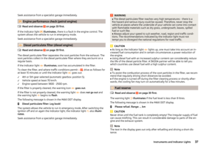 39
39 40
40 41
41 42
42 43
43 44
44 45
45 46
46 47
47 48
48 49
49 50
50 51
51 52
52 53
53 54
54 55
55 56
56 57
57 58
58 59
59 60
60 61
61 62
62 63
63 64
64 65
65 66
66 67
67 68
68 69
69 70
70 71
71 72
72 73
73 74
74 75
75 76
76 77
77 78
78 79
79 80
80 81
81 82
82 83
83 84
84 85
85 86
86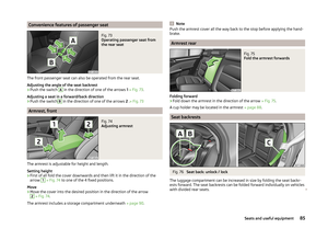 87
87 88
88 89
89 90
90 91
91 92
92 93
93 94
94 95
95 96
96 97
97 98
98 99
99 100
100 101
101 102
102 103
103 104
104 105
105 106
106 107
107 108
108 109
109 110
110 111
111 112
112 113
113 114
114 115
115 116
116 117
117 118
118 119
119 120
120 121
121 122
122 123
123 124
124 125
125 126
126 127
127 128
128 129
129 130
130 131
131 132
132 133
133 134
134 135
135 136
136 137
137 138
138 139
139 140
140 141
141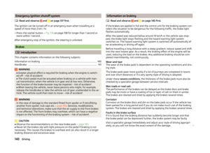 142
142 143
143 144
144 145
145 146
146 147
147 148
148 149
149 150
150 151
151 152
152 153
153 154
154 155
155 156
156 157
157 158
158 159
159 160
160 161
161 162
162 163
163 164
164 165
165 166
166 167
167 168
168 169
169 170
170 171
171 172
172 173
173 174
174 175
175 176
176 177
177 178
178 179
179 180
180 181
181 182
182 183
183 184
184 185
185 186
186 187
187 188
188 189
189 190
190 191
191 192
192 193
193 194
194 195
195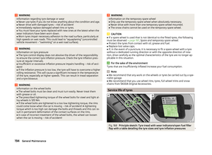 196
196 197
197 198
198 199
199 200
200 201
201 202
202 203
203 204
204 205
205 206
206 207
207 208
208 209
209 210
210 211
211 212
212 213
213 214
214 215
215 216
216 217
217 218
218 219
219 220
220 221
221 222
222 223
223 224
224 225
225 226
226 227
227 228
228 229
229 230
230 231
231 232
232 233
233 234
234 235
235 236
236 237
237 238
238 239
239 240
240 241
241 242
242 243
243 244
244 245
245