2014 NISSAN TEANA wiring diagram
[x] Cancel search: wiring diagramPage 4201 of 4801

STARTING SYSTEMSTR-11
< WIRING DIAGRAM >
C
D E
F
G H
I
J
K L
M A
STR
NP
O
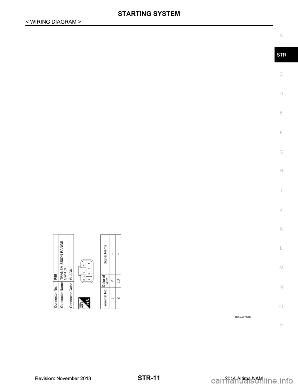
ABBIA1278GB
Revision: November 20132014 Altima NAMRevision: November 20132014 Altima NAM
Page 4208 of 4801

STR-18
< DTC/CIRCUIT DIAGNOSIS >
B TERMINAL CIRCUIT
DTC/CIRCUIT DIAGNOSIS
B TERMINAL CIRCUIT
DescriptionINFOID:0000000009461229
Terminal “B” is constantly supplied with battery power.
Diagnosis ProcedureINFOID:0000000009461230
Regarding Wiring Diagram information, refer to STR-7, "Wiring Diagram".
CAUTION:
Perform diagnosis under the condi tion that the engine cannot start by the following procedure.
1. Remove fuel pump fuse.
2. Crank or start the engine (where possi ble) until the fuel pressure is released.
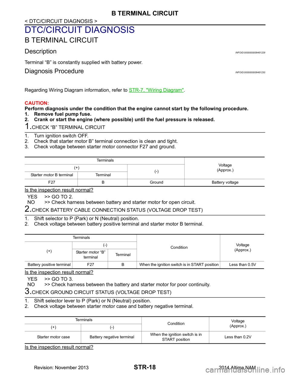
1.CHECK “B” TERMINAL CIRCUIT
1. Turn ignition switch OFF.
2. Check that starter motor B” terminal connection is clean and tight.
3. Check voltage between starter motor connector F27 and ground.
Is the inspection result normal?
YES >> GO TO 2.
NO >> Check harness between battery and starter motor for open circuit.
2.CHECK BATTERY CABLE CONNECTION STATUS (VOLTAGE DROP TEST)
1. Shift selector to P (Park) or N (Neutral) position.
2. Check voltage between battery positive terminal and starter motor B terminal.
Is the inspection result normal?
YES >> GO TO 3.
NO >> Check harness between the battery and starter motor for poor continuity.
3.CHECK GROUND CIRCUIT STATUS (VOLTAGE DROP TEST)
1. Shift selector lever to P (Park) or N (Neutral) position.
2. Check voltage between starter motor case and battery negative terminal.
Is the inspection result normal?
Te r m i n a l s
Voltage
(Approx.)
(+)
(-)
Starter motor B terminal Terminal
F27 B Ground Battery voltage
Te r m i n a l s
ConditionVoltage
(Approx.)
(+) (-)
Starter motor “B” terminal Te r m i n a l
Battery positive terminal F27 B When the ignition switch is in START position Less than 0.5V
Te r m i n a l s ConditionVoltage
(Approx.)
(+) (-)
Starter motor case Battery negative terminal When the ignition switch is in
START position Less than 0.2V
Revision: November 20132014 Altima NAMRevision: November 20132014 Altima NAM
Page 4210 of 4801

STR-20
< DTC/CIRCUIT DIAGNOSIS >
S CONNECTOR CIRCUIT
S CONNECTOR CIRCUIT
DescriptionINFOID:0000000009461231
The starter motor magnetic switch is supplied with power when the ignition switch is turned to the START posi-
tion while the selector lever is in the P (Park) or N (Neutral) position.
Diagnosis ProcedureINFOID:0000000009461232
Regarding Wiring Diagram information, refer to STR-7, "Wiring Diagram".
CAUTION:
Perform diagnosis under the condi tion that engine cannot start by the following procedure.
1. Remove fuel pump fuse.
2. Crank or start the engine (where possi ble) until the fuel pressure is released.
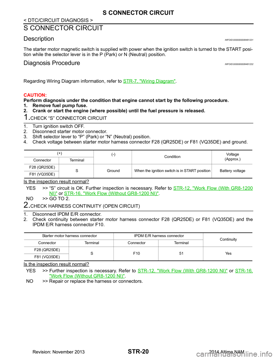
1.CHECK “S” CONNECTOR CIRCUIT
1. Turn ignition switch OFF.
2. Disconnect starter motor connector.
3. Shift selector lever to “P” (Park) or “N” (Neutral) position.
4. Check voltage between starter motor harness con nector F28 (QR25DE) or F81 (VQ35DE) and ground.
Is the inspection result normal?
YES >> “S” circuit is OK. Further inspection is necessary. Refer to STR-12, "Work Flow (With GR8-1200
NI)" or STR-16, "Work Flow (Without GR8-1200 NI)".
NO >> GO TO 2.
2.CHECK HARNESS CONTI NUITY (OPEN CIRCUIT)
1. Disconnect IPDM E/R connector.
2. Check continuity between starter motor harness connector F28 (QR25DE) or F81 (VQ35DE) and the
IPDM E/R harness connector F10.
Is the inspection result normal?
YES >> Further inspection is necessary. Refer to STR-12, "Work Flow (With GR8-1200 NI)" or STR-16,
"Work Flow (Without GR8-1200 NI)".
NO >> Repair or replace the harness or connectors.
(+) (-)
Condition Voltage
(Approx.)
Connector Terminal
F28 (QR25DE) S Ground When the ignition switch is in START position Battery voltage
F81 (VQ35DE)
Starter motor harness connector IPDM E/R harness connector Continuity
Connector Terminal Connector Terminal
F28 (QR25DE) S F10 51 Yes
F81 (VQ35DE)
Revision: November 20132014 Altima NAMRevision: November 20132014 Altima NAM
Page 4217 of 4801

TM-2
CVT CONTROL SYSTEM : Fail-safe .................. ...31
CVT CONTROL SYSTEM : Protection Control ... ...34
LINE PRESSURE CONTROL ................................ ...35
LINE PRESSURE CONTROL : System Descrip-
tion ....................................................................... ...
35
SHIFT CONTROL ................................................... ...35
SHIFT CONTROL : System Description .................36
SELECT CONTROL ............................................... ...37
SELECT CONTROL : System Description .............38
LOCK-UP CONTROL ............................................. ...38
LOCK-UP CONTROL : System Description ...........38
ON BOARD DIAGNOSTIC (OBD) SYSTEM .....40
Description ........................................................... ...40
Function of OBD .....................................................40
DIAGNOSIS SYSTEM (TCM) ............................41
DIAGNOSIS DESCRIPTION .................................. ...41
DIAGNOSIS DESCRIPTION : 1 Trip Detection Di-
agnosis and 2 Trip Detection Diagnosis .............. ...
41
DIAGNOSIS DESCRIPTION : DTC and DTC of
1st Trip ................................................................. ...
41
DIAGNOSIS DESCRIPTION : Malfunction Indica-
tor Lamp (MIL) ..................................................... ...
41
DIAGNOSIS DESCRIPTION : Counter System .....41
CONSULT Function ................................................43
ECU DIAGNOSIS INFORMATION ..............49
TCM ................................................................. ...49
Reference Value .................................................. ...49
Fail-safe ..................................................................56
Protection Control ...................................................59
DTC Inspection Priority Chart .................................59
DTC Index ..............................................................60
WIRING DIAGRAM .....................................62
CVT CONTROL SYSTEM ............................... ...62
Wiring diagram .................................................... ...62
CVT SHIFT LOCK SYSTEM ........................... ...73
Wiring diagram .................................................... ...73
BASIC INSPECTION ...................................77
DIAGNOSIS AND REPAIR WORK FLOW ..... ...77
Flowchart of Trouble Diagnosis ........................... ...77
Question sheet .......................................................78
ADDITIONAL SERVICE WHEN REPLACING
TCM ................................................................. ...
80
Description ........................................................... ...80
Work Procedure ......................................................80
ADDITIONAL SERVICE WHEN REPLACING
TRANSAXLE ASSEMBLY ............................. ...
81
Description ........................................................... ...81
Work Procedure ................................................... ...81
CVT FLUID ........................................................83
Replacement ........................................................ ...83
Adjustment ..............................................................84
STALL TEST .....................................................86
Work Procedure ................................................... ...86
CVT POSITION ..................................................87
Inspection ............................................................. ...87
Adjustment ..............................................................87
DTC/CIRCUIT DIAGNOSIS ........................88
U0073 COMMUNICATION BUS A OFF ......... ...88
DTC Logic ............................................................ ...88
Diagnosis Procedure ...............................................88
U0100 LOST COMMUNICATION (ECM A) .......89
DTC Logic ............................................................ ...89
Diagnosis Procedure ...............................................89
U0140 LOST COMMUNICATION (BCM) ..........90
DTC Logic ............................................................ ...90
Diagnosis Procedure ...............................................90
U0141 LOST COMMUNICATION (BCM A) ......91
DTC Logic ............................................................ ...91
Diagnosis Procedure ...............................................91
U0155 LOST COMMUNICATION (IPC) ............92
DTC Logic ............................................................ ...92
Diagnosis Procedure ...............................................92
U0300 CAN COMMUNICATION DATA ............93
DTC Logic ............................................................ ...93
Diagnosis Procedure ...............................................93
U1000 CAN COMM CIRCUIT ............................94
Description ........................................................... ...94
DTC Logic ...............................................................94
Diagnosis Procedure ...............................................94
U1117 LOST COMMUNICATION (ABS) ...........95
DTC Logic ............................................................ ...95
Diagnosis Procedure ...............................................95
P062F EEPROM ................................................96
Description ........................................................... ...96
DTC Logic ...............................................................96
Diagnosis Procedure ...............................................96
P0705 TRANSMISSION RANGE SENSOR A ...97
DTC Logic ............................................................ ...97
Diagnosis Procedure ...............................................97
Component Inspection ..........................................101
P0706 TRANSMISSION RANGE SENSOR A ..103
DTC Logic ............................................................ .103
Diagnosis Procedure .............................................103
Component Inspection ..........................................105
Revision: November 20132014 Altima NAMRevision: November 20132014 Altima NAM
Page 4221 of 4801

TM-6
Fail-safe .................................................................258
Protection Control ..................................................261
DTC Inspection Priority Chart ................................262
DTC Index .............................................................263
WIRING DIAGRAM ....................................265
CVT CONTROL SYSTEM ............................... .265
Wiring diagram .................................................... ..265
CVT SHIFT LOCK SYSTEM ........................... .275
Wiring Diagram .................................................... ..275
BASIC INSPECTION ..................................279
DIAGNOSIS AND REPAIR WORK FLOW ..... .279
Work Flow ............................................................ ..279
Diagnostic Work Sheet ..........................................280
ADDITIONAL SERVICE WHEN REPLACING
TCM ................................................................. .
282
Description ........................................................... ..282
Work Procedure .....................................................282
ADDITIONAL SERVICE WHEN REPLACING
TRANSAXLE ASSEMBLY ............................. .
283
Description ........................................................... ..283
Work Procedure .....................................................283
CVT FLUID .......................................................285
Replacement ....................................................... ..285
Adjustment .............................................................286
STALL TEST ....................................................288
Work Procedure ................................................... ..288
CVT POSITION ................................................289
Inspection ............................................................ ..289
Adjustment .............................................................289
DTC/CIRCUIT DIAGNOSIS ...................... ..290
U0073 COMMUNICATION BUS A OFF ......... .290
DTC Logic ............................................................ ..290
Diagnosis Procedure .............................................290
U0100 LOST COMMUNICATION (ECM A) .....291
DTC Logic ............................................................ ..291
Diagnosis Procedure .............................................291
U0140 LOST COMMUNICATION (BCM) ........292
DTC Logic ............................................................ ..292
Diagnosis Procedure .............................................292
U0141 LOST COMMUNICATION (BCM A) .....293
DTC Logic ............................................................ ..293
Diagnosis Procedure .............................................293
U0155 LOST COMMUNICATION (IPC) ..........294
DTC Logic ............................................................ ..294
Diagnosis Procedure .............................................294
U0300 CAN COMMUNICATION DATA ...........295
DTC Logic ............................................................ .295
Diagnosis Procedure .............................................295
U1000 CAN COMM CIRCUIT ...........................296
Description ........................................................... .296
DTC Logic .............................................................296
Diagnosis Procedure .............................................296
U1117 LOST COMMUNICATION (ABS) ..........297
DTC Logic ............................................................ .297
Diagnosis Procedure .............................................297
P062F EEPROM ...............................................298
Description ........................................................... .298
DTC Logic .............................................................298
Diagnosis Procedure .............................................298
P0705 TRANSMISSION RANGE SENSOR A ..299
DTC Logic ............................................................ .299
Diagnosis Procedure .............................................299
Component Inspection ..........................................303
P0706 TRANSMISSION RANGE SENSOR A ..305
DTC Logic ............................................................ .305
Diagnosis Procedure .............................................305
Component Inspection ..........................................307
P0711 TRANSMISSION FLUID TEMPERA-
TURE SENSOR A ........................................... ..
308
DTC Logic ............................................................ .308
Diagnosis Procedure .............................................309
P0712 TRANSMISSION FLUID TEMPERA-
TURE SENSOR A ........................................... ..
312
DTC Logic ............................................................ .312
Diagnosis Procedure .............................................312
Component Inspection ..........................................312
P0713 TRANSMISSION FLUID TEMPERA-
TURE SENSOR A ........................................... ..
314
DTC Logic ............................................................ .314
Diagnosis Procedure .............................................314
Component Inspection ..........................................315
P0715 INPUT SPEED SENSOR A ...................316
DTC Logic ............................................................ .316
Diagnosis Procedure .............................................317
P0717 INPUT SPEED SENSOR A ...................319
DTC Logic ............................................................ .319
Diagnosis Procedure .............................................320
P0740 TORQUE CONVERTER ........................322
DTC Logic ............................................................ .322
Diagnosis Procedure .............................................323
P0743 TORQUE CONVERTER ........................324
DTC Logic ............................................................ .324
Diagnosis Procedure .............................................325
P0744 TORQUE CONVERTER ........................326
DTC Logic ............................................................ .326
Revision: November 20132014 Altima NAMRevision: November 20132014 Altima NAM
Page 4277 of 4801
![NISSAN TEANA 2014 Service Manual
TM-62
< WIRING DIAGRAM >[CVT: RE0F10D]
CVT CONTROL SYSTEM
WIRING DIAGRAM
CVT CONTROL SYSTEM
Wiring diagramINFOID:0000000009464006
ABDWA0699GB
Revision: November 20132014 Altima NAMRevision: November NISSAN TEANA 2014 Service Manual
TM-62
< WIRING DIAGRAM >[CVT: RE0F10D]
CVT CONTROL SYSTEM
WIRING DIAGRAM
CVT CONTROL SYSTEM
Wiring diagramINFOID:0000000009464006
ABDWA0699GB
Revision: November 20132014 Altima NAMRevision: November](/manual-img/5/57390/w960_57390-4276.png)
TM-62
< WIRING DIAGRAM >[CVT: RE0F10D]
CVT CONTROL SYSTEM
WIRING DIAGRAM
CVT CONTROL SYSTEM
Wiring diagramINFOID:0000000009464006
ABDWA0699GB
Revision: November 20132014 Altima NAMRevision: November 20132014 Altima NAM
Page 4278 of 4801
![NISSAN TEANA 2014 Service Manual
CVT CONTROL SYSTEMTM-63
< WIRING DIAGRAM > [CVT: RE0F10D]
C
EF
G H
I
J
K L
M A
B
TM
N
O P
ABDWA0700GB
Revision: November 20132014 Altima NAMRevision: November 20132014 Altima NAM NISSAN TEANA 2014 Service Manual
CVT CONTROL SYSTEMTM-63
< WIRING DIAGRAM > [CVT: RE0F10D]
C
EF
G H
I
J
K L
M A
B
TM
N
O P
ABDWA0700GB
Revision: November 20132014 Altima NAMRevision: November 20132014 Altima NAM](/manual-img/5/57390/w960_57390-4277.png)
CVT CONTROL SYSTEMTM-63
< WIRING DIAGRAM > [CVT: RE0F10D]
C
EF
G H
I
J
K L
M A
B
TM
N
O P
ABDWA0700GB
Revision: November 20132014 Altima NAMRevision: November 20132014 Altima NAM
Page 4279 of 4801
![NISSAN TEANA 2014 Service Manual
TM-64
< WIRING DIAGRAM >[CVT: RE0F10D]
CVT CONTROL SYSTEM
ABDIA1148GB
Revision: November 20132014 Altima NAMRevision: November 20132014 Altima NAM NISSAN TEANA 2014 Service Manual
TM-64
< WIRING DIAGRAM >[CVT: RE0F10D]
CVT CONTROL SYSTEM
ABDIA1148GB
Revision: November 20132014 Altima NAMRevision: November 20132014 Altima NAM](/manual-img/5/57390/w960_57390-4278.png)
TM-64
< WIRING DIAGRAM >[CVT: RE0F10D]
CVT CONTROL SYSTEM
ABDIA1148GB
Revision: November 20132014 Altima NAMRevision: November 20132014 Altima NAM