Page 3691 of 4801

RF-26
< DTC/CIRCUIT DIAGNOSIS >
MOONROOF SWITCH
MOONROOF SWITCH
DescriptionINFOID:0000000009461309
Transmits switch operation signal to moonroof motor assembly.
Diagnosis ProcedureINFOID:0000000009461310
Regarding Wiring Diagram information, refer to RF-12, "Wiring Diagram".
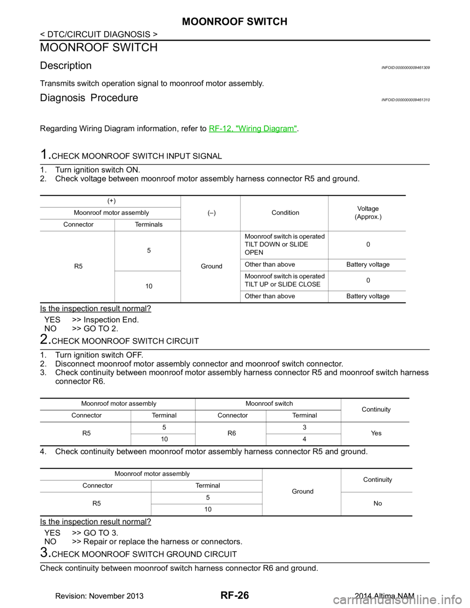
1.CHECK MOONROOF SWITCH INPUT SIGNAL
1. Turn ignition switch ON.
2. Check voltage between moonroof motor assembly harness connector R5 and ground.
Is the inspection result normal?
YES >> Inspection End.
NO >> GO TO 2.
2.CHECK MOONROOF SWITCH CIRCUIT
1. Turn ignition switch OFF.
2. Disconnect moonroof motor assembly connector and moonroof switch connector.
3. Check continuity between moonroof motor assemb ly harness connector R5 and moonroof switch harness
connector R6.
4. Check continuity between moonroof moto r assembly harness connector R5 and ground.
Is the inspection result normal?
YES >> GO TO 3.
NO >> Repair or replace the harness or connectors.
3.CHECK MOONROOF SWITCH GROUND CIRCUIT
Check continuity between moonroof switch harness connector R6 and ground.
(+)
(–) Condition Voltag e
(Approx.)
Moonroof motor assembly
Connector Terminals
R5 5
GroundMoonroof switch is operated
TILT DOWN or SLIDE
OPEN 0
Other than above Battery voltage
10 Moonroof switch is operated
TILT UP or SLIDE CLOSE 0
Other than above Battery voltage
Moonroof motor assembly Moonroof switch Continuity
Connector Terminal Connector Terminal
R5 5
R6 3
Ye s
10 4
Moonroof motor assembly GroundContinuity
Connector Terminal
R5 5
No
10
Revision: November 20132014 Altima NAMRevision: November 20132014 Altima NAM
Page 3693 of 4801

RF-28
< DTC/CIRCUIT DIAGNOSIS >
DOOR SWITCH
DOOR SWITCH
DescriptionINFOID:0000000009461312
Detects door open/close condition.
Component Function CheckINFOID:0000000009461313
1.CHECK FUNCTION
With CONSULT
Check door switches DOOR SW-DR, DOOR SW-AS in Data Monitor mode with CONSULT.
Is the inspection result normal?
YES >> Door switch is OK.
NO >> Refer to RF-28, "Diagnosis Procedure"
.
Diagnosis ProcedureINFOID:0000000009461314
Regarding Wiring Diagram information, refer to DLK-51, "Wiring Diagram".
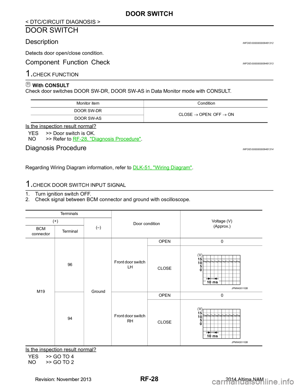
1.CHECK DOOR SWITCH INPUT SIGNAL
1. Turn ignition switch OFF.
2. Check signal between BCM connector and ground with oscilloscope.
Is the inspection result normal?
YES >> GO TO 4
NO >> GO TO 2
Monitor item Condition
DOOR SW-DR CLOSE → OPEN: OFF → ON
DOOR SW-AS
Te r m i n a l s
Door condition Voltage (V)
(Approx.)
(+)
(–)
BCM
connector Te r m i n a l
M19 96
GroundFront door switch
LH OPEN 0
CLOSE
94 Front door switch
RH OPEN 0
CLOSE
JPMIA0011GB
JPMIA0011GB
Revision: November 20132014 Altima NAMRevision: November 20132014 Altima NAM
Page 3750 of 4801

SE-1
BODY INTERIOR
C
D E
F
G H
I
K L
M
SECTION SE
A
B
SE
N
O P
CONTENTS
SEAT
PRECAUTION ................ ...............................2
PRECAUTIONS .............................................. .....2
Precaution for Supplemental Restraint System
(SRS) "AIR BAG" and "SEAT BELT PRE-TEN-
SIONER" ............................................................. ......
2
Precaution for Work ..................................................2
PREPARATION ............................................3
PREPARATION .............................................. .....3
Special Service Tools .......................................... ......3
Commercial Service Tool ..........................................3
CLIP LIST ............................................................4
Descriptions for Clips .......................................... ......4
WIRING DIAGRAM .......................................8
POWER SEAT FOR DRIVER SIDE ............... .....8
Wiring Diagram ................................................... ......8
HEATED SEAT ...................................................12
Wiring Diagram ................................................... ....12
SYMPTOM DIAGNOSIS ..............................17
SQUEAK AND RATTLE TROUBLE DIAG-
NOSES ........................................................... ....
17
Work Flow ........................................................... ....17
Generic Squeak and Rattle Troubleshooting ..........18
Diagnostic Worksheet .............................................21
REMOVAL AND INSTALLATION ...............23
FRONT SEAT ................................................. ....23
DRIVER SIDE ........................................................ ....23
DRIVER SIDE : Exploded View ..............................23
DRIVER SIDE : Removal and Installation - Seat
Assembly ............................................................. ....
26
DRIVER SIDE : Removal and Installation - Seat-
back Board .......................................................... ....
27
DRIVER SIDE : Removal and Installation - Lum-
bar Support Assembly ......................................... ....
27
PASSENGER SIDE ....................................................28
PASSENGER SIDE : Explode d View ......................29
PASSENGER SIDE : Removal and Installation -
Seat Assembly ..................................................... ....
30
PASSENGER SIDE : Removal and Installation -
Seatback Board ................................................... ....
31
HEATED SEAT SWITCH ....................................... ....31
HEATED SEAT SWITCH : Removal and Installa-
tion ....................................................................... ....
31
REAR SEAT ......................................................33
Exploded View .........................................................33
Removal and Installation - Seat Cushion Assem-
bly ........................................................................ ....
36
Removal and Installation - Seat Assembly ..............36
Removal and Installation - Seatback Hinge .............37
Removal and Installation - Seatback Latch As-
sembly ................................................................. ....
37
Removal and Installation - Armrest Assembly .........38
Removal and Installation - Rear Seat Bolster ..........38
UNIT DISASSEMBLY AND ASSEMBLY ....39
FRONT SEAT ....................................................39
DRIVER SIDE ......................................................... ....39
DRIVER SIDE : Exploded View ...............................39
DRIVER SIDE : Disassembly and Assembly ...........42
DRIVER SIDE : Side air bag module .......................50
PASSENGER SIDE ....................................................53
PASSENGER SIDE : Explode d View ......................54
PASSENGER SIDE : Disassembly and Assembly ....55
PASSENGER SIDE : Side air bag module ..............62
REAR SEAT ......................................................66
Exploded View .........................................................66
Disassembly and Assembly .....................................69
Revision: November 20132014 Altima NAMRevision: November 20132014 Altima NAM
Page 3757 of 4801
SE-8
< WIRING DIAGRAM >
POWER SEAT FOR DRIVER SIDE
WIRING DIAGRAM
POWER SEAT FOR DRIVER SIDE
Wiring DiagramINFOID:0000000009462928
ABJWA0365GB
Revision: November 20132014 Altima NAMRevision: November 20132014 Altima NAM
Page 3758 of 4801
POWER SEAT FOR DRIVER SIDESE-9
< WIRING DIAGRAM >
C
D E
F
G H
I
K L
M A
B
SE
N
O P
ABJIA0861GB
Revision: November 20132014 Altima NAMRevision: November 20132014 Altima NAM
Page 3759 of 4801
SE-10
< WIRING DIAGRAM >
POWER SEAT FOR DRIVER SIDE
AAJIA0158GB
Revision: November 20132014 Altima NAMRevision: November 20132014 Altima NAM
Page 3760 of 4801
POWER SEAT FOR DRIVER SIDESE-11
< WIRING DIAGRAM >
C
D E
F
G H
I
K L
M A
B
SE
N
O P
AAJIA0159GB
Revision: November 20132014 Altima NAMRevision: November 20132014 Altima NAM
Page 3761 of 4801
SE-12
< WIRING DIAGRAM >
HEATED SEAT
HEATED SEAT
Wiring DiagramINFOID:0000000009462929
ABJWA0364GB
Revision: November 20132014 Altima NAMRevision: November 20132014 Altima NAM