2014 NISSAN TEANA wiring diagram
[x] Cancel search: wiring diagramPage 3625 of 4801
![NISSAN TEANA 2014 Service Manual
PWC-118
< DTC/CIRCUIT DIAGNOSIS >[LH & RH FRONT ANTI-PINCH]
DOOR SWITCH
DOOR SWITCH
DescriptionINFOID:0000000009460950
Detects door open/close condition.
Component Function CheckINFOID:00000000094609 NISSAN TEANA 2014 Service Manual
PWC-118
< DTC/CIRCUIT DIAGNOSIS >[LH & RH FRONT ANTI-PINCH]
DOOR SWITCH
DOOR SWITCH
DescriptionINFOID:0000000009460950
Detects door open/close condition.
Component Function CheckINFOID:00000000094609](/manual-img/5/57390/w960_57390-3624.png)
PWC-118
< DTC/CIRCUIT DIAGNOSIS >[LH & RH FRONT ANTI-PINCH]
DOOR SWITCH
DOOR SWITCH
DescriptionINFOID:0000000009460950
Detects door open/close condition.
Component Function CheckINFOID:0000000009460951
1.CHECK FUNCTION
With CONSULT
Check door switches DOOR SW-DR, DOOR SW-AS in Data Monitor mode with CONSULT.
Is the inspection result normal?
YES >> Door switch is OK.
NO >> Refer to PWC-118, "Diagnosis Procedure"
.
Diagnosis ProcedureINFOID:0000000009460952
Regarding Wiring Diagram information, refer to DLK-51, "Wiring Diagram".
1.CHECK DOOR SWITCH INPUT SIGNAL
1. Turn ignition switch OFF.
2. Check signal between BCM connector and ground with oscilloscope.
Is the inspection result normal?
YES >> GO TO 4
NO >> GO TO 2
Monitor item Condition
DOOR SW-DR CLOSE → OPEN: OFF → ON
DOOR SW-AS
Te r m i n a l s
Door condition Voltage (V)
(Approx.)
(+)
(–)
BCM
connector Te r m i n a l
M19 96
GroundFront door switch
LH OPEN 0
CLOSE
94 Front door switch
RH OPEN 0
CLOSE
JPMIA0011GB
JPMIA0011GB
Revision: November 20132014 Altima NAMRevision: November 20132014 Altima NAM
Page 3627 of 4801
![NISSAN TEANA 2014 Service Manual
PWC-120
< DTC/CIRCUIT DIAGNOSIS >[LH & RH FRONT ANTI-PINCH]
DOOR KEY CYLINDER SWITCH
DOOR KEY CYLINDER SWITCH
DescriptionINFOID:0000000009460954
Power window main switch detects condition of the door NISSAN TEANA 2014 Service Manual
PWC-120
< DTC/CIRCUIT DIAGNOSIS >[LH & RH FRONT ANTI-PINCH]
DOOR KEY CYLINDER SWITCH
DOOR KEY CYLINDER SWITCH
DescriptionINFOID:0000000009460954
Power window main switch detects condition of the door](/manual-img/5/57390/w960_57390-3626.png)
PWC-120
< DTC/CIRCUIT DIAGNOSIS >[LH & RH FRONT ANTI-PINCH]
DOOR KEY CYLINDER SWITCH
DOOR KEY CYLINDER SWITCH
DescriptionINFOID:0000000009460954
Power window main switch detects condition of the door
key cylinder and transmits to BCM as the LOCK or
UNLOCK signals.
Component Function CheckINFOID:0000000009460955
1. CHECK DOOR KEY CYLINDER SWITCH INPUT SIGNAL
Check (“KEY CYL LK-SW”, “KEY CYL UN-SW”) in “DAT A MONITOR” mode for “POWER DOOR LOCK SYS-
TEM” with CONSULT. Refer to BCS-15, "DOOR LOCK : CONSULT Function (BCM - DOOR LOCK)"
.
Is the inspection result normal?
YES >> Key cylinder switch is OK.
NO >> Refer to PWC-120, "Diagnosis Procedure"
.
Diagnosis ProcedureINFOID:0000000009460956
Regarding Wiring Diagram information, refer to PWC-83, "Wiring Diagram - With Left And Right Front Power
Window Anti-Pinch".
1. CHECK DOOR KEY CYLINDER SWITCH INPUT SIGNAL
1. Turn ignition switch ON.
2. Check voltage between main power window and door lock/unlock switch connector D7 and ground.
Is the inspection result normal?
YES >> Replace main power window and door lock/unlock switch. After that, refer to PWC-122, "Special
Repair Requirement".
NO >> GO TO 2.
2. CHECK DOOR KEY CYLINDER SIGNAL CIRCUIT
1. Turn ignition switch OFF.
2. Disconnect main power window and door lock/unlock switch and front door lock assembly LH (key cylin- der switch).
3. Check continuity between main power window and door lock/unlock switch connector D7 and front door
lock assembly LH (key cylinder switch) connector D14.
Monitor item Condition
KEY CYL LK-SW Lock : ON
Neutral / Unlock : OFF
KEY CYL UN-SW Unlock : ON
Neutral / Lock : OFF
Te r m i n a l s
Key positionVoltag e
(Approx.)
(+)
(–)
Main power window and door
lock/unlock switch connector Te r m i n a l
D7 3
Ground Lock 0
Neutral/Unlock 5
15 Unlock 0
Neutral/Lock 5
Revision: November 20132014 Altima NAMRevision: November 20132014 Altima NAM
Page 3630 of 4801
![NISSAN TEANA 2014 Service Manual
POWER WINDOW SERIAL LINKPWC-123
< DTC/CIRCUIT DIAGNOSIS > [LH & RH FRONT ANTI-PINCH]
C
D E
F
G H
I
J
L
M A
B
PWC
N
O P
POWER WINDOW SERIAL LINK
POWER WINDOW MAIN SWITCH
POWER WINDOW MAIN SWITCH : D NISSAN TEANA 2014 Service Manual
POWER WINDOW SERIAL LINKPWC-123
< DTC/CIRCUIT DIAGNOSIS > [LH & RH FRONT ANTI-PINCH]
C
D E
F
G H
I
J
L
M A
B
PWC
N
O P
POWER WINDOW SERIAL LINK
POWER WINDOW MAIN SWITCH
POWER WINDOW MAIN SWITCH : D](/manual-img/5/57390/w960_57390-3629.png)
POWER WINDOW SERIAL LINKPWC-123
< DTC/CIRCUIT DIAGNOSIS > [LH & RH FRONT ANTI-PINCH]
C
D E
F
G H
I
J
L
M A
B
PWC
N
O P
POWER WINDOW SERIAL LINK
POWER WINDOW MAIN SWITCH
POWER WINDOW MAIN SWITCH : DescriptionINFOID:0000000009460959
Main power window and door lock/unlock switch, pow er window and door lock/unlock switch RH and BCM
transmit and receive the signal by power window serial link.
The signal mentioned below is transmitted from BCM to main power window and door lock/unlock switch and
power window and door lock/unlock switch RH
• Keyless power window down signal
The signal mentioned below is transmitted from main pow er window and door lock/unlock switch to power win-
dow and door lock/unlock switch RH
• Front door window RH operation signal
• Power window control by key cylinder switch signal
• Power window lock switch signal
• Retained power operation signal
POWER WINDOW MAIN SWITCH : Component Function CheckINFOID:0000000009460960
1. CHECK POWER WINDOW SWITCH OUTPUT SIGNAL
Check (“CDL LOCK SW ”, “CDL UNLOCK SW”) in “D ATA MONITOR” mode for “POWER DOOR LOCK SYS-
TEM” with CONSULT. Refer to BCS-15, "DOOR LOCK : CONSULT Function (BCM - DOOR LOCK)"
.
Is the inspection result normal?
YES >> Power window serial link is OK.
NO >> Refer to PWC-123, "POWER WINDOW MAIN SWITCH : Diagnosis Procedure"
.
POWER WINDOW MAIN SWITCH : Diagnosis ProcedureINFOID:0000000009460961
Regarding Wiring Diagram information, refer to PWC-83, "Wiring Diagram - With Left And Right Front Power
Window Anti-Pinch".
Power Window Serial Link Check
1. CHECK POWER WINDOW SWITCH OUTPUT SIGNAL
1. Remove Intelligent Key, and close front door LH and RH.
2. Check signal between BCM connector and ground wit h oscilloscope when door lock and unlock switch
(LH and RH) is turned to “LOCK” or “UNLOCK”.
3. Check that signals which are shown in the figure below can be detected during 10 second just after door
lock and unlock switch (LH and RH) is turned to “LOCK” or “UNLOCK”.
Monitor item Condition
CDL LOCK SW LOCK : ON
UNLOCK : OFF
CDL UNLOCK SW LOCK : OFF
UNLOCK : ON
Revision: November 20132014 Altima NAMRevision: November 20132014 Altima NAM
Page 3632 of 4801
![NISSAN TEANA 2014 Service Manual
POWER WINDOW SERIAL LINKPWC-125
< DTC/CIRCUIT DIAGNOSIS > [LH & RH FRONT ANTI-PINCH]
C
D E
F
G H
I
J
L
M A
B
PWC
N
O P
Is the inspection result normal?
YES >> Power window serial link is OK.
NO >> NISSAN TEANA 2014 Service Manual
POWER WINDOW SERIAL LINKPWC-125
< DTC/CIRCUIT DIAGNOSIS > [LH & RH FRONT ANTI-PINCH]
C
D E
F
G H
I
J
L
M A
B
PWC
N
O P
Is the inspection result normal?
YES >> Power window serial link is OK.
NO >>](/manual-img/5/57390/w960_57390-3631.png)
POWER WINDOW SERIAL LINKPWC-125
< DTC/CIRCUIT DIAGNOSIS > [LH & RH FRONT ANTI-PINCH]
C
D E
F
G H
I
J
L
M A
B
PWC
N
O P
Is the inspection result normal?
YES >> Power window serial link is OK.
NO >> Refer to PWC-125, "FRONT POWER WINDO W SWITCH : Diagnosis Procedure"
.
FRONT POWER WINDOW SWITCH : Diagnosis ProcedureINFOID:0000000009460964
Regarding Wiring Diagram information, refer to PWC-83, "Wiring Diagram - With Left And Right Front Power
Window Anti-Pinch".
Power Window Serial Link Check
1. CHECK POWER WINDOW AND DOOR LOCK/UNLOCK SWITCH RH
1. Remove Intelligent Key, and close the front door LH and RH.
2. Check signal between BCM connector and ground wit h oscilloscope when door lock and unlock switch
(LH and RH) is turned to “LOCK” or “UNLOCK”.
3. Check that signals which are shown in the figure below can be detected during 10 second just after door lock and unlock switch (LH and RH) is turned to “LOCK” or “UNLOCK”.
Is the inspection result normal?
YES >> Power window serial link is OK.
NO >> GO TO 2.
2. CHECK POWER WINDOW SERIAL LINK CIRCUIT
1. Turn ignition switch OFF.
2. Disconnect BCM.
3. Check continuity between BCM connector M18 and power window and door lock/unlock switch RH con-
nector D105.
4. Check continuity between BCM connector M18 and ground.
Monitor item Condition
CDL LOCK SW LOCK : ON
UNLOCK : OFF
CDL UNLOCK SW LOCK : OFF
UNLOCK : ON
Te r m i n a l Signal
(Reference value)
(+)
(–)
BCM connector Terminal
M18 54 Ground
PIIA1297E
BCM connector Terminal Power window and door lock/unlock switch RH
connector Terminal Continuity
M18 54 D105 3 Yes
BCM connector Terminal GroundContinuity
M18 54 No
Revision: November 20132014 Altima NAMRevision: November 20132014 Altima NAM
Page 3652 of 4801

PWO
PWO-1
ELECTRICAL & POWER CONTROL
C
D E
F
G H
I
J
K L
B
SECTION PWO
A
O P
N
CONTENTS
POWER OUTLET
PRECAUTION ................
...............................2
PRECAUTIONS .............................................. .....2
Precaution for Supplemental Restraint System
(SRS) "AIR BAG" and "SEAT BELT PRE-TEN-
SIONER" ............................................................. ......
2
PREPARATION ............................................3
PREPARATION .............................................. .....3
Special Service Tool ........................................... ......3
WIRING DIAGRAM .......................................4
POWER SOCKET ..............................................4
Wiring Diagram .................................................... .....4
REMOVAL AND INSTALLATION ................6
POWER SOCKET ..............................................6
Removal and Installation ..................................... .....6
Revision: November 20132014 Altima NAMRevision: November 20132014 Altima NAM
Page 3655 of 4801

PWO-4
< WIRING DIAGRAM >
POWER SOCKET
WIRING DIAGRAM
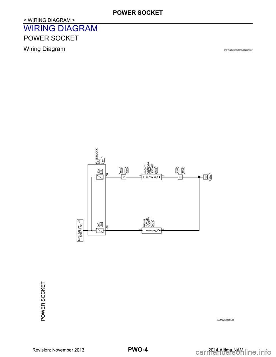
POWER SOCKET
Wiring DiagramINFOID:0000000009460697
ABMWA2168GB
Revision: November 20132014 Altima NAMRevision: November 20132014 Altima NAM
Page 3656 of 4801

PWO
POWER SOCKETPWO-5
< WIRING DIAGRAM >
C
D E
F
G H
I
J
K L
B
A
O P
N
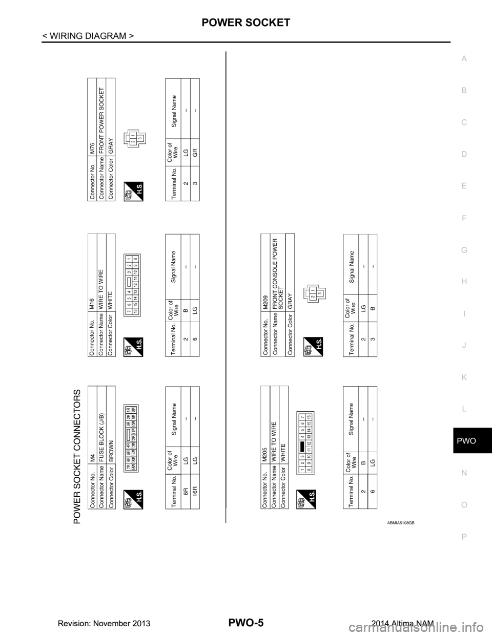
ABMIA5108GB
Revision: November 20132014 Altima NAMRevision: November 20132014 Altima NAM
Page 3666 of 4801

RF-1
BODY EXTERIOR, DOORS, ROOF & VEHICLE SECURITY
C
D E
F
G H
I
J
L
M
SECTION RF
A
B
RF
N
O P
CONTENTS
ROOF
PRECAUTION ................ ...............................3
PRECAUTIONS .............................................. .....3
Precaution for Supplemental Restraint System
(SRS) "AIR BAG" and "SEAT BELT PRE-TEN-
SIONER" ............................................................. ......
3
Precaution for Work ..................................................3
PREPARATION ............................................4
PREPARATION .............................................. .....4
Special Service Tools ........................................ ......4
Commercial Service Tools .......................................4
SYSTEM DESCRIPTION ..............................5
COMPONENT PARTS ................................... .....5
MOONROOF .......................................................... ......5
MOONROOF : Component Parts Location .............5
MOONROOF : Component Description ...................5
SYSTEM ..............................................................6
MOONROOF .......................................................... ......6
MOONROOF : System Diagram ..............................6
MOONROOF : System Description ...........................6
DIAGNOSIS SYSTEM (BCM) .............................8
COMMON ITEM ..................................................... ......8
COMMON ITEM : CONSULT Function (BCM -
COMMON ITEM) ................................................. ......
8
RETAINED PWR ................................................... ......8
RETAINED PWR : CONSULT Function (BCM -
RETAINED PWR) ............................................... ......
9
ECU DIAGNOSIS INFORMATION ..............10
BCM (BODY CONTROL MODULE) ............... ....10
List of ECU Reference ........................................ ....10
MOONROOF MOTOR ASSEMBLY ...................11
Reference Value .................................................. ....11
WIRING DIAGRAM ......................................12
MOONROOF SYSTEM .....................................12
Wiring Diagram .................................................... ....12
BASIC INSPECTION ...................................18
DIAGNOSIS AND REPAIR WORKFLOW ........18
Work Flow ............................................................ ....18
INSPECTION AND ADJUSTMENT ..................20
ADDITIONAL SERVICE WHEN REPLACING
CONTROL UNIT .................................................... ....
20
ADDITIONAL SERVICE WHEN REPLACING
CONTROL UNIT : Description ............................. ....
20
ADDITIONAL SERVICE WHEN REPLACING
CONTROL UNIT : Special Repair Requirement .. ....
20
DTC/CIRCUIT DIAGNOSIS .........................21
POWER SUPPLY AND GROUND CIRCUIT ....21
BCM ....................................................................... ....21
BCM : Diagnosis Procedure ....................................21
MOONROOF MOTOR ASSEMBLY ...........................21
MOONROOF MOTOR ASSEM BLY : Description ....21
MOONROOF MO TOR ASSEMBLY :
Component Function Check .............................. ....
22
MOONROOF MOTOR ASSEMBLY :
Diagnosis Procedure .......................................... ....
22
MOONROOF MOTOR ASSEMBLY : Component
Inspection ............................................................ ....
24
MOONROOF MOTOR ASSEMBLY : Special Re-
pair Requirement ................................................. ....
25
MOONROOF SWITCH ......................................26
Description ...............................................................26
Diagnosis Procedure ..............................................26
Component Inspection .............................................27
Revision: November 20132014 Altima NAMRevision: November 20132014 Altima NAM