2014 NISSAN TEANA ECU
[x] Cancel search: ECUPage 3988 of 4801
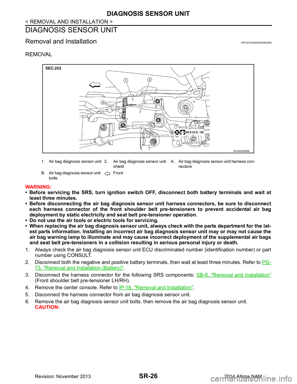
SR-26
< REMOVAL AND INSTALLATION >
DIAGNOSIS SENSOR UNIT
DIAGNOSIS SENSOR UNIT
Removal and InstallationINFOID:0000000009463080
REMOVAL
WARNING:
• Before servicing the SRS, turn ig nition switch OFF, disconnect both battery terminals and wait at
least three minutes.
• Before disconnecting the air bag diagnosis sensor unit harness conn ectors, be sure to disconnect
each harness connector of the front shoulder belt pre-tensioners to prevent accidental air bag
deployment by static electricity and seat belt pre-tensioner operation.
• Do not use the air tools or electric tools for servicing.
• When replacing the air bag diagno sis sensor unit, always check with th e parts department for the lat-
est parts information. Installing an incorrect air bag diagnosis sen sor unit may or may not cause the
air bag warning lamp to illuminate and may cause in correct deployment of the supplemental air bags
and seat belt pre-tensioners in a collision r esulting in serious personal injury or death.
1. Always check the air bag diagnosis sensor unit ECU discriminated number (identification number) or part
number using CONSULT.
2. Disconnect both the negative and positive battery terminal s, then wait at least three minutes. Refer to PG-
73, "Removal and Installation (Battery)".
3. Disconnect the harness connector fo r the following SRS components: SB-8, "Removal and Installation"
(Front shoulder belt pre-tensioner LH/RH).
4. Remove the center console. Refer to IP-18, "Removal and Installation"
.
5. Disconnect the harness connector from air bag diagnosis sensor unit.
6. Remove the air bag diagnosis sensor unit bolts , then remove the air bag diagnosis sensor unit.
CAUTION:
1. Air bag diagnosis sensor unit 2. Air bag diagnosis sensor unit
shieldA. Air bag diagnosis sensor unit harness con-
nectors
B. Air bag diagnosis sensor unit bolts Front
ALHIA0258GB
Revision: November 20132014 Altima NAM
Page 3989 of 4801
DIAGNOSIS SENSOR UNITSR-27
< REMOVAL AND INSTALLATION >
C
D E
F
G
I
J
K L
M A
B
SR
N
O P
• Do not reuse the air bag di agnosis sensor unit bolts.
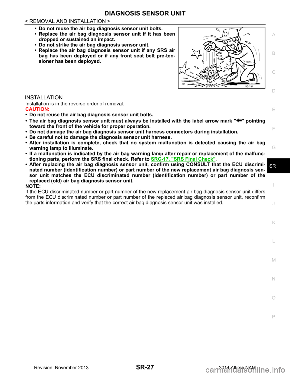
• Replace the air bag diagnosis sensor unit if it has been
dropped or sustained an impact.
• Do not strike the air ba g diagnosis sensor unit.
• Replace the air bag diagnosis sensor unit if any SRS air
bag has been deployed or if any front seat belt pre-ten-
sioner has been deployed.
INSTALLATION
Installation is in the reverse order of removal.
CAUTION:
• Do not reuse the air bag diagnosis sensor unit bolts.
• The air bag diagnosis sensor unit must always be installed with the label arrow mark " " pointing
toward the front of the vehicle for proper operation.
• Do not damage the air bag diagnosis sensor unit harness connectors during installation.
• Be careful not to damage the diagnosis sensor unit harness.
• After installation is complete, check that no syst em malfunction is detected causing the air bag
warning lamp to illuminate.
• If a malfunction is indicated by the air bag warnin g lamp after repair or replacement of the malfunc-
tioning parts, perform the SRS final check. Refer to SRC-17, "SRS Final Check"
.
• After replacing the air bag diagnosis sensor un it, confirm using CONSULT that the ECU discrimi-
nated number (identification number) or part nu mber of the new replacement air bag diagnosis sen-
sor unit matches the ECU discrimin ated number (identification number) or part number of the
replaced (old) air bag diagnosis sensor unit.
NOTE:
If the ECU discriminated number or pa rt number of the new replacement air bag diagnosis sensor unit differs
from the ECU discriminated number or part number of the replaced air bag diagnosis sensor unit, reconfirm
the parts information and verify that the corre ct air bag diagnosis sensor unit was installed.
SGI787
Revision: November 20132014 Altima NAM
Page 3994 of 4801

SRC-1
RESTRAINTS
C
D E
F
G
I
J
K L
M
SECTION SRC
A
B
SRC
N
O P
CONTENTS
SRS AIRBAG CONTROL SYSTEM
PRECAUTION ................ ...............................4
PRECAUTIONS .............................................. .....4
Precaution for Supplemental Restraint System
(SRS) "AIR BAG" and "SEAT BELT PRE-TEN-
SIONER" ............................................................. ......
4
Precaution for SRS "AIR BAG" and "SEAT BELT
PRE-TENSIONER" Service ................................ ......
4
SYSTEM DESCRIPTION ..............................5
COMPONENT PARTS ................................... .....5
Component Parts Location .................................. ......5
Component Description .............................................6
Driver Air Bag Module ...............................................7
Front Passenger Air Bag Module ..............................7
Front Side Air Bag Module .................................. ......7
Side Curtain Air Bag Module .....................................7
Front Seat Belt Pre-tensioner ....................................8
Air Bag Diagnosis Sensor Unit ..................................8
Crash Zone Sensor ...................................................8
Front Side Air Bag Satellite Sensor ...........................8
Rear Side Air Bag Satellite Sensor ...........................9
Front Door Satellite Sensor .......................................9
SRS Component Connectors ....................................9
SYSTEM .............................................................11
SRS AIR BAG SYSTEM ............................................11
SRS AIR BAG SYSTEM : Sy stem Diagram ............11
SRS AIR BAG SYSTEM : System Description ... ....11
OCCUPANT CLASSIFICATION SYSTEM ............ ....11
OCCUPANT CLASSIFICATION SYSTEM : Sys-
tem Diagram ........................................................ ....
12
OCCUPANT CLASSIFICATION SYSTEM : Sys-
tem Description ................................................... ....
12
SEAT BELT WARNING LAMP SYSTEM ..................13
SEAT BELT WARNING LAMP SYSTEM : System
Diagram ............................................................... ....
13
SEAT BELT WARNING LAMP SYSTEM : System
Description ........................................................... ....
14
DIAGNOSIS SYSTEM (AIR BAG) ....................15
Diagnosis Description ..............................................15
SRS Operation Check .............................................15
Trouble Diagnosis with CONSULT ..........................16
Trouble Diagnosis without CONSULT .....................17
SRS History Check ..................................................17
SRS Final Check .....................................................17
CONSULT Function (AIR BAG) ...............................17
CONSULT Function (OCCUPANT DETECTION) ....18
ECU DIAGNOSIS INFORMATION ..............19
DIAGNOSIS SENSOR UNIT .............................19
DTC Index ........................................................... ....19
Flash Code Index ....................................................23
WIRING DIAGRAM ......................................26
SRS AIR BAG SYSTEM ...................................26
Wiring Diagram .................................................... ....26
BASIC INSPECTION ...................................40
DIAGNOSIS AND REPAIR WORK FLOW .......40
Work Flow ............................................................ ....40
INSPECTION AND ADJUSTMENT ..................42
ADDITIONAL SERVICE WHEN REPLACING
CONTROL UNIT .................................................... ....
42
ADDITIONAL SERVICE WHEN REPLACING
CONTROL UNIT : Description ............................. ....
42
ADDITIONAL SERVICE WHEN REPLACING
CONTROL UNIT : Special Repair Requirement .. ....
42
ZERO POINT RESET ............................................. ....42
ZERO POINT RESET : Description .........................42
ZERO POINT RESET : Special Repair Require-
ment ..................................................................... ....
42
Revision: November 20132014 Altima NAMRevision: November 20132014 Altima NAM
Page 4001 of 4801
SRC-8
< SYSTEM DESCRIPTION >
COMPONENT PARTS
Front Seat Belt Pre-tensioner
INFOID:0000000009460710
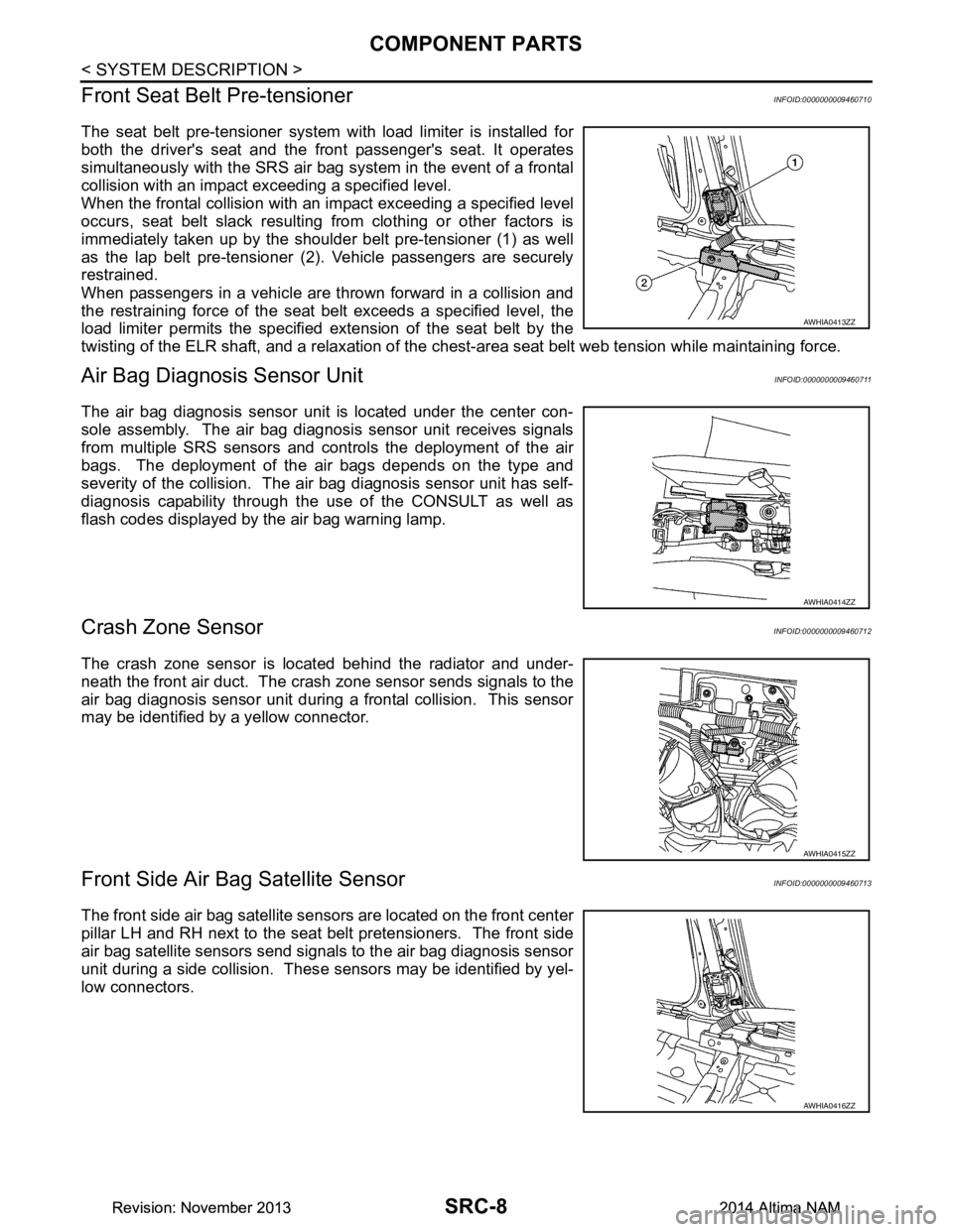
The seat belt pre-tensioner system wi th load limiter is installed for
both the driver's seat and the front passenger's seat. It operates
simultaneously with the SRS air bag system in the event of a frontal
collision with an impact exceeding a specified level.
When the frontal collision with an im pact exceeding a specified level
occurs, seat belt slack resulting from clothing or other factors is
immediately taken up by the shoulder belt pre-tensioner (1) as well
as the lap belt pre-tensioner (2). Vehicle passengers are securely
restrained.
When passengers in a vehicle are thrown forward in a collision and
the restraining force of the seat belt exceeds a specified level, the
load limiter permits the specified extension of the seat belt by the
twisting of the ELR shaft, and a relaxation of the ches t-area seat belt web tension while maintaining force.
Air Bag Diagnosis Sensor UnitINFOID:0000000009460711
The air bag diagnosis sensor unit is located under the center con-
sole assembly. The air bag diagnosis sensor unit receives signals
from multiple SRS sensors and cont rols the deployment of the air
bags. The deployment of the air bags depends on the type and
severity of the collision. The air bag diagnosis sensor unit has self-
diagnosis capability through the use of the CONSULT as well as
flash codes displayed by the air bag warning lamp.
Crash Zone SensorINFOID:0000000009460712
The crash zone sensor is located behind the radiator and under-
neath the front air duct. The crash zone sensor sends signals to the
air bag diagnosis sensor unit during a frontal collision. This sensor
may be identified by a yellow connector.
Front Side Air B ag Satellite SensorINFOID:0000000009460713
The front side air bag satellite sensors are located on the front center
pillar LH and RH next to the seat belt pretensioners. The front side
air bag satellite sensors send signals to the air bag diagnosis sensor
unit during a side collision. Thes e sensors may be identified by yel-
low connectors.
AWHIA0413ZZ
AWHIA0414ZZ
AWHIA0415ZZ
AWHIA0416ZZ
Revision: November 20132014 Altima NAMRevision: November 20132014 Altima NAM
Page 4010 of 4801
DIAGNOSIS SYSTEM (AIR BAG)SRC-17
< SYSTEM DESCRIPTION >
C
D E
F
G
I
J
K L
M A
B
SRC
N
O P
Trouble Diagnosis without CONSULTINFOID:0000000009460726
DIAGNOSIS MODE
NOTE:
Diagnosis Mode can not be entered if a malfunction is not detected in User Mode.
1. Turn ignition switch ON.
2. After AIR BAG warning lamp lights for 7 seconds, turn ignition switch OFF within 1 second.
3. Wait more than 3 seconds.
4. Repeat steps 1 to 3 two more times (3 times total).
5. Turn ignition switch ON.
SRS is now in Diagnosis Mode. Refer to SRC-23, "Flash Code Index"
.
SRS History CheckINFOID:0000000009460727
SRS HISTORY CHECK
1. Check repair history of the SRS. If no repairs have been made, perform SRC-15, "SRS Operation
Check". If repairs have been made, GO TO step 2.
2. Erase "SELF-DIAG [PAST]" after repair. Refer to SRC-17, "SRS Final Check"
.
SRS Final CheckINFOID:0000000009460728
DIAGNOSIS MODE
1. Connect CONSULT.
2. Confirm that zero point reset of OCS is complete.
3. If no DTCs are detected on “SELF- DIAG RESULTS [CURRENT]”, repair of SRS is completed. Go to step
4.
If any DTCs are detected on “SEL F-DIAG RESULTS [CURRENT]”, t he malfunction has not been repaired
completely or another malfunction is being detected. Perform SRS Operation Check again. Refer to
SRC-15, "SRS Operation Check"
.
4. Touch “ERASE”. NOTE:
Touching “ERASE” will clear the SRS memory of the malfunction (“SELF-DIAG [PAST]”). If “SELF-
DIAG [PAST]” is not erased, User Mode may s how the previous system malfunction even if the
malfunction has been repaired completely.
5. Check that no malfunction is detected in “SELF-DIAG [PAST]”.
6. Exit Diagnosis Mode and disconnect the CONSULT.
7. Perform SRS Operation Check. Refer to SRC-15, "SRS Operation Check"
.
CONSULT Function (AIR BAG)INFOID:0000000009460729
CAUTION:
After disconnecting the CONSULT vehicle interface (VI) from the data link connector, the ignition must
be cycled OFF → ON (for at least 5 seconds) → OFF. If this step is not performed, the BCM may not go
to ”sleep mode”, potentiall y causing a discharged battery and a no-start condition.
CONSULT can display each diagnostic item using the diagnostic test modes shown following.
Diagnostic Test Mode Diagnostic Item Description
Self Diagnostic Result SEL F-DIAG RESULT [CURRENT]A current Self-diagnosis result (also indicated by the number of
warning lamp flashes in the Diagnosis mode) is displayed on the
CONSULT screen in real time. This refers to a malfunctioning part
requiring repairs.
Data Monitor DATA MONITOR Displays air bag diagnosis sensor unit input/output data in real time.
Ecu Identification ECU DISCRIMINATED NO. Air bag diagnosis sensor unit ECU discriminated number (identifica-
tion number) or part number is displayed. Air bag diagnosis sensor
unit has individual ECU discriminated number (identification num-
ber) or part number based on model and equipment.
Trouble Diagnostic Record TROUBLE DIAG RECORD [PAST] With TROUBLE DIAG RECORD, diagnosis results previously
erased by a reset operation can be displayed on the CONSULT
screen.
Revision: November 20132014 Altima NAMRevision: November 20132014 Altima NAM
Page 4012 of 4801
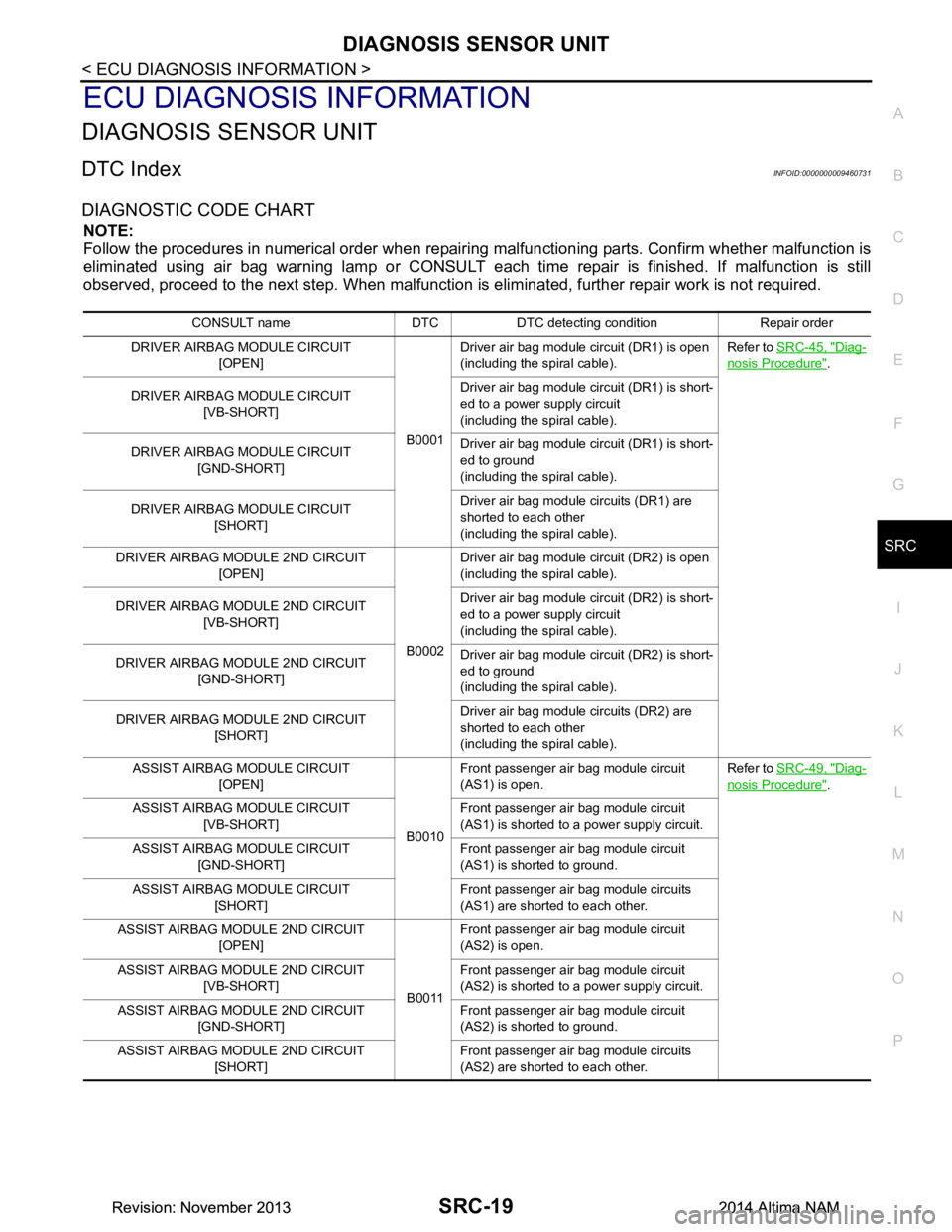
DIAGNOSIS SENSOR UNITSRC-19
< ECU DIAGNOSIS INFORMATION >
C
D E
F
G
I
J
K L
M A
B
SRC
N
O P
ECU DIAGNOSIS INFORMATION
DIAGNOSIS SENSOR UNIT
DTC IndexINFOID:0000000009460731
DIAGNOSTIC CODE CHART
NOTE:
Follow the procedures in numerical order when repairi ng malfunctioning parts. Confirm whether malfunction is
eliminated using air bag warning lamp or CONSULT each time repair is finished. If malfunction is still
observed, proceed to the next step. When malfunction is elim inated, further repair work is not required.
CONSULT name DTC DTC detecting condition Repair order
DRIVER AIRBAG MODULE CIRCUIT [OPEN]
B0001Driver air bag module circuit (DR1) is open
(including the spiral cable). Refer to
SRC-45, "Diag-
nosis Procedure".
DRIVER AIRBAG MODULE CIRCUIT [VB-SHORT] Driver air bag module circuit (DR1) is short-
ed to a power supply circuit
(including the spiral cable).
DRIVER AIRBAG MODULE CIRCUIT [GND-SHORT] Driver air bag module circuit (DR1) is short-
ed to ground
(including the spiral cable).
DRIVER AIRBAG MODULE CIRCUIT [SHORT] Driver air bag module circuits (DR1) are
shorted to each other
(including the spiral cable).
DRIVER AIRBAG MODULE 2ND CIRCUIT [OPEN]
B0002Driver air bag module circuit (DR2) is open
(including the spiral cable).
DRIVER AIRBAG MODULE 2ND CIRCUIT [VB-SHORT] Driver air bag module circuit (DR2) is short-
ed to a power supply circuit
(including the spiral cable).
DRIVER AIRBAG MODULE 2ND CIRCUIT [GND-SHORT] Driver air bag module circuit (DR2) is short-
ed to ground
(including the spiral cable).
DRIVER AIRBAG MODULE 2ND CIRCUIT [SHORT] Driver air bag module circuits (DR2) are
shorted to each other
(including the spiral cable).
ASSIST AIRBAG MODULE CIRCUIT [OPEN]
B0010Front passenger air bag module circuit
(AS1) is open. Refer to
SRC-49, "Diag-
nosis Procedure".
ASSIST AIRBAG MODULE CIRCUIT [VB-SHORT] Front passenger air bag module circuit
(AS1) is shorted to a power supply circuit.
ASSIST AIRBAG MODULE CIRCUIT [GND-SHORT] Front passenger air bag module circuit
(AS1) is shorted to ground.
ASSIST AIRBAG MODULE CIRCUIT [SHORT] Front passenger air bag module circuits
(AS1) are shorted to each other.
ASSIST AIRBAG MODULE 2ND CIRCUIT [OPEN]
B0011Front passenger air bag module circuit
(AS2) is open.
ASSIST AIRBAG MODULE 2ND CIRCUIT [VB-SHORT] Front passenger air bag module circuit
(AS2) is shorted to a power supply circuit.
ASSIST AIRBAG MODULE 2ND CIRCUIT [GND-SHORT] Front passenger air bag module circuit
(AS2) is shorted to ground.
ASSIST AIRBAG MODULE 2ND CIRCUIT [SHORT] Front passenger air bag module circuits
(AS2) are shorted to each other.
Revision: November 20132014 Altima NAMRevision: November 20132014 Altima NAM
Page 4013 of 4801
![NISSAN TEANA 2014 Service Manual
SRC-20
< ECU DIAGNOSIS INFORMATION >
DIAGNOSIS SENSOR UNIT
SIDE AIRBAG MODULE LH CIRCUIT [OPEN]
B0020Front LH side air bag module circuit is open. Refer to
SRC-52, "Diag-
nosis Procedure".
SIDE AIRB NISSAN TEANA 2014 Service Manual
SRC-20
< ECU DIAGNOSIS INFORMATION >
DIAGNOSIS SENSOR UNIT
SIDE AIRBAG MODULE LH CIRCUIT [OPEN]
B0020Front LH side air bag module circuit is open. Refer to
SRC-52, "Diag-
nosis Procedure".
SIDE AIRB](/manual-img/5/57390/w960_57390-4012.png)
SRC-20
< ECU DIAGNOSIS INFORMATION >
DIAGNOSIS SENSOR UNIT
SIDE AIRBAG MODULE LH CIRCUIT [OPEN]
B0020Front LH side air bag module circuit is open. Refer to
SRC-52, "Diag-
nosis Procedure".
SIDE AIRBAG MODULE LH CIRCUIT [VB-SHORT] Front LH side air bag module circuit is short-
ed to a power supply circuit.
SIDE AIRBAG MODULE LH CIRCUIT [GND-SHORT] Front LH side air bag module circuit is short-
ed to ground.
SIDE AIRBAG MODULE LH CIRCUIT [SHORT] Front LH side air bag module circuits are
shorted to each other.
SIDE AIRBAG MODULE RH CIRCUIT [OPEN]
B0028Front RH side air bag module circuit is open. Refer to
SRC-55, "Diag-
nosis Procedure".
SIDE AIRBAG MODULE RH CIRCUIT [VB-SHORT] Front RH side air bag module circuit is short-
ed to a power supply circuit.
SIDE AIRBAG MODULE RH CIRCUIT [GND-SHORT] Front RH side air bag module circuit is short-
ed to ground.
SIDE AIRBAG MODULE RH CIRCUIT [SHORT] Front RH side air bag module circuits are
shorted to each other.
CURTAIN AIRBAG MODULE LH CIRCUIT [OPEN]
B0021LH side curtain air bag module circuit is
open. Refer to
SRC-58, "Diag-
nosis Procedure".
CURTAIN AIRBAG MODULE LH CIRCUIT [VB-SHORT] LH side curtain air bag module circuit is
shorted to a power supply circuit.
CURTAIN AIRBAG MODULE LH CIRCUIT [GND-SHORT] LH side curtain air bag module circuit is
shorted to ground.
CURTAIN AIRBAG MODULE LH CIRCUIT [SHORT] LH side curtain air bag module circuits are
shorted to each other.
CURTAIN AIRBAG MODULE RH CIRCUIT [OPEN]
B0029RH side curtain air bag module circuit is
open. Refer to
SRC-61, "Diag-
nosis Procedure".
CURTAIN AIRBAG MODULE RH CIRCUIT [VB-SHORT] RH side curtain air bag module circuit is
shorted to a power supply circuit.
CURTAIN AIRBAG MODULE RH CIRCUIT [GND-SHORT] RH side curtain air bag module circuit is
shorted to ground.
CURTAIN AIRBAG MODULE RH CIRCUIT [SHORT] RH side curtain air bag module circuits are
shorted to each other.
FRONT PRE-TEN LH CIRCUIT [OPEN]
B1430LH seat belt pre-tensioner circuit is open.
(shoulder belt) Refer to
SRC-64, "Diag-
nosis Procedure".
FRONT PRE-TEN LH CIRCUIT [VB-SHORT] LH seat belt pre-tensioner circuit is shorted
to a power supply circuit. (shoulder belt)
FRONT PRE-TEN LH CIRCUIT [GND-SHORT] LH seat belt pre-tensioner circuit is shorted
to ground. (shoulder belt)
FRONT PRE-TEN LH CIRCUIT [SHORT] LH seat belt pre-tensioner circuits are short-
ed to each other. (shoulder belt)
FRONT PRE-TEN2 LH CIRCUIT [OPEN]
B1432LH seat belt pre-tensioner circuit is open.
(lap belt) Refer to
SRC-64, "Diag-
nosis Procedure".
FRONT PRE-TEN2 LH CIRCUIT [VB-SHORT] LH seat belt pre-tensioner circuit is shorted
to a power supply circuit. (lap belt)
FRONT PRE-TEN2 LH CIRCUIT [GND-SHORT] LH seat belt pre-tensioner circuit is shorted
to ground. (lap belt)
FRONT PRE-TEN2 LH CIRCUIT [SHORT] LH seat belt pre-tensioner circuits are short-
ed to each other. (lap belt)
CONSULT name DTC DTC detecting condition Repair order
Revision: November 20132014 Altima NAMRevision: November 20132014 Altima NAM
Page 4014 of 4801
![NISSAN TEANA 2014 Service Manual
DIAGNOSIS SENSOR UNITSRC-21
< ECU DIAGNOSIS INFORMATION >
C
D E
F
G
I
J
K L
M A
B
SRC
N
O P
FRONT PRE-TEN RH CIRCUIT [OPEN]
B1431RH seat belt pre-tensioner circuit is open.
(shoulder belt) Refer NISSAN TEANA 2014 Service Manual
DIAGNOSIS SENSOR UNITSRC-21
< ECU DIAGNOSIS INFORMATION >
C
D E
F
G
I
J
K L
M A
B
SRC
N
O P
FRONT PRE-TEN RH CIRCUIT [OPEN]
B1431RH seat belt pre-tensioner circuit is open.
(shoulder belt) Refer](/manual-img/5/57390/w960_57390-4013.png)
DIAGNOSIS SENSOR UNITSRC-21
< ECU DIAGNOSIS INFORMATION >
C
D E
F
G
I
J
K L
M A
B
SRC
N
O P
FRONT PRE-TEN RH CIRCUIT [OPEN]
B1431RH seat belt pre-tensioner circuit is open.
(shoulder belt) Refer to
SRC-67, "Diag-
nosis Procedure".
FRONT PRE-TEN RH CIRCUIT [VB-SHORT] RH seat belt pre-tensioner circuit is shorted
to a power supply circuit. (shoulder belt)
FRONT PRE-TEN RH CIRCUIT [GND-SHORT] RH seat belt pre-tensioner circuit is shorted
to ground. (shoulder belt)
FRONT PRE-TEN RH CIRCUIT [SHORT] RH seat belt pre-tensioner circuits are short-
ed to each other. (shoulder belt)
FRONT PRE-TEN2 RH CIRCUIT [OPEN]
B1433RH seat belt pre-tensioner circuit is open.
(lap belt) Refer to
SRC-67, "Diag-
nosis Procedure".
FRONT PRE-TEN2 RH CIRCUIT [VB-SHORT] RH seat belt pre-tensioner circuit is shorted
to a power supply circuit. (lap belt)
FRONT PRE-TEN2 RH CIRCUIT [GND-SHORT] RH seat belt pre-tensioner circuit is shorted
to ground. (lap belt)
FRONT PRE-TEN2 RH CIRCUIT [SHORT] RH seat belt pre-tensioner circuits are short-
ed to each other. (lap belt)
SEAT BELT BUCKLE SW LH CIRCUIT [OPEN]
B1428LH seat belt buckle switch circuit is open. Refer to
SRC-97, "Diag-
nosis Procedure".
SEAT BELT BUCKLE SW LH CIRCUIT [VB-SHORT] LH seat belt buckle switch circuit is shorted
to a power supply circuit.
SEAT BELT BUCKLE SW LH CIRCUIT [GND-SHORT] LH seat belt buckle switch circuit is shorted
to ground.
SEAT BELT BUCKLE SW LH CIRCUIT [UNDEFINED] LH seat belt buckle switch circuit malfunc-
tion.
SEAT BELT BUCKLE SW RH CIRCUIT [OPEN]
B1429RH seat belt buckle switch circuit is open. Refer to
SRC-99, "Diag-
nosis Procedure".
SEAT BELT BUCKLE SW RH CIRCUIT [VB-SHORT] RH seat belt buckle switch circuit is shorted
to a power supply circuit.
SEAT BELT BUCKLE SW RH CIRCUIT [GND-SHORT] RH seat belt buckle switch circuit is shorted
to ground.
SEAT BELT BUCKLE SW RH CIRCUIT [UNDEFINED] RH seat belt buckle switch circuit malfunc-
tion.
CRASH ZONE SENSOR [SENSOR FAIL]
B0094Crash zone sensor has malfunctioned. Refer to
SRC-70, "Diag-
nosis Procedure".
CRASH ZONE SENSOR [COMM FAIL] Crash zone sensor communication error.
CRASH ZONE SENSOR [DISCONNECT] Crash zone sensor is disconnected.
CRASH ZONE SENSOR [UNMATCH] Crash zone sensor is out of specification.
CRASH ZONE SENSOR [GND-SHORT] Crash zone sensor circuit is shorted to
ground.
DOOR SATELLITE SENSOR LH [SENSOR FAIL]
B0093Front door satellite sensor LH has malfunc-
tioned. Refer to
SRC-85, "Diag-
nosis Procedure".
DOOR SATELLITE SENSOR LH [COMM FAIL] Front door satellite sensor LH communica-
tion error.
DOOR SATELLITE SENSOR LH [DISCONNECT] Front door satellite sensor LH is disconnect-
ed.
DOOR SATELLITE SENSOR LH [UNMATCH] Front door satellite sensor LH is out of spec-
ification.
DOOR SATELLITE SENSOR LH [GND-SHORT] Front door satellite sensor LH circuit is
shorted to ground.
CONSULT name DTC DTC detecting condition Repair order
Revision: November 20132014 Altima NAMRevision: November 20132014 Altima NAM