2014 NISSAN TEANA mirror
[x] Cancel search: mirrorPage 918 of 4801

DLK-150
< DTC/CIRCUIT DIAGNOSIS >
HOMELINK UNIVERSAL TRANSCEIVER
HOMELINK UNIVERSAL TRANSCEIVER
DescriptionINFOID:0000000009461904
Homelink universal transceiver can store and transmit a maximum of 3 radio signals.
Allows operation of garage doors, gates, home and office lighting, entry door locks and security system, etc.
Homelink universal transceiver power supply uses vehicl e battery, which enables it to maintain every program
in case battery is discharged or removed.
Component Function CheckINFOID:0000000009461905
1.CHECK FUNCTION
Check that system receiver (garage door opener, et c.) operates with original hand-held transmitter.
Is the inspection result normal?
YES >> GO TO 2
NO >> Receiver or hand-held transmitter is malfunctioning.
2.CHECK ILLUMINATE
1. Turn ignition switch “OFF”.
2. Press each of the transmitter buttons and watch for the red light to illuminate with each button.
Is the inspection result normal?
YES >> GO TO 3
NO >> Refer to DLK-150, "Diagnosis Procedure"
.
3.CHECK TRANSMITTER
Check transmitter with Tool*.
*:For details, refer to Technical Service Bulletin.
Is the inspection result normal?
YES >> Receiver or hand-held transmitter malfunction, not vehicle related.
NO >> Replace auto anti-dazzling inside mirror (homelink universal transceiver). Refer to MIR-19,
"Removal and Installation".
Diagnosis ProcedureINFOID:0000000009461906
Regarding Wiring Diagram information, refer to DLK-49, "Wiring Diagram".
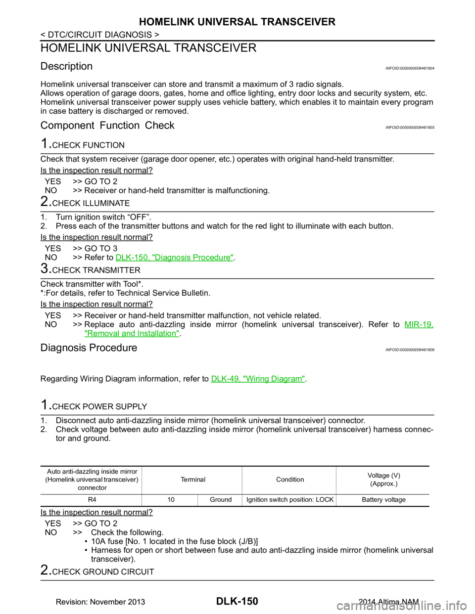
1.CHECK POWER SUPPLY
1. Disconnect auto anti-dazzling inside mirror (homelink universal transceiver) connector.
2. Check voltage between auto anti-dazzling inside mirror (homelink universal transceiver) harness connec-
tor and ground.
Is the inspection result normal?
YES >> GO TO 2
NO >> Check the following. • 10A fuse [No. 1 located in the fuse block (J/B)]
• Harness for open or short between fuse and auto anti-dazzling inside mirror (homelink universal
transceiver).
2.CHECK GROUND CIRCUIT
Auto anti-dazzling inside mirror
(Homelink universal transceiver) connector Terminal Condition
Voltage (V)
(Approx.)
R4 10 Ground Ignition switch position: LOCK Battery voltage
Revision: November 20132014 Altima NAMRevision: November 20132014 Altima NAM
Page 919 of 4801

HOMELINK UNIVERSAL TRANSCEIVERDLK-151
< DTC/CIRCUIT DIAGNOSIS >
C
D E
F
G H
I
J
L
M A
B
DLK
N
O P
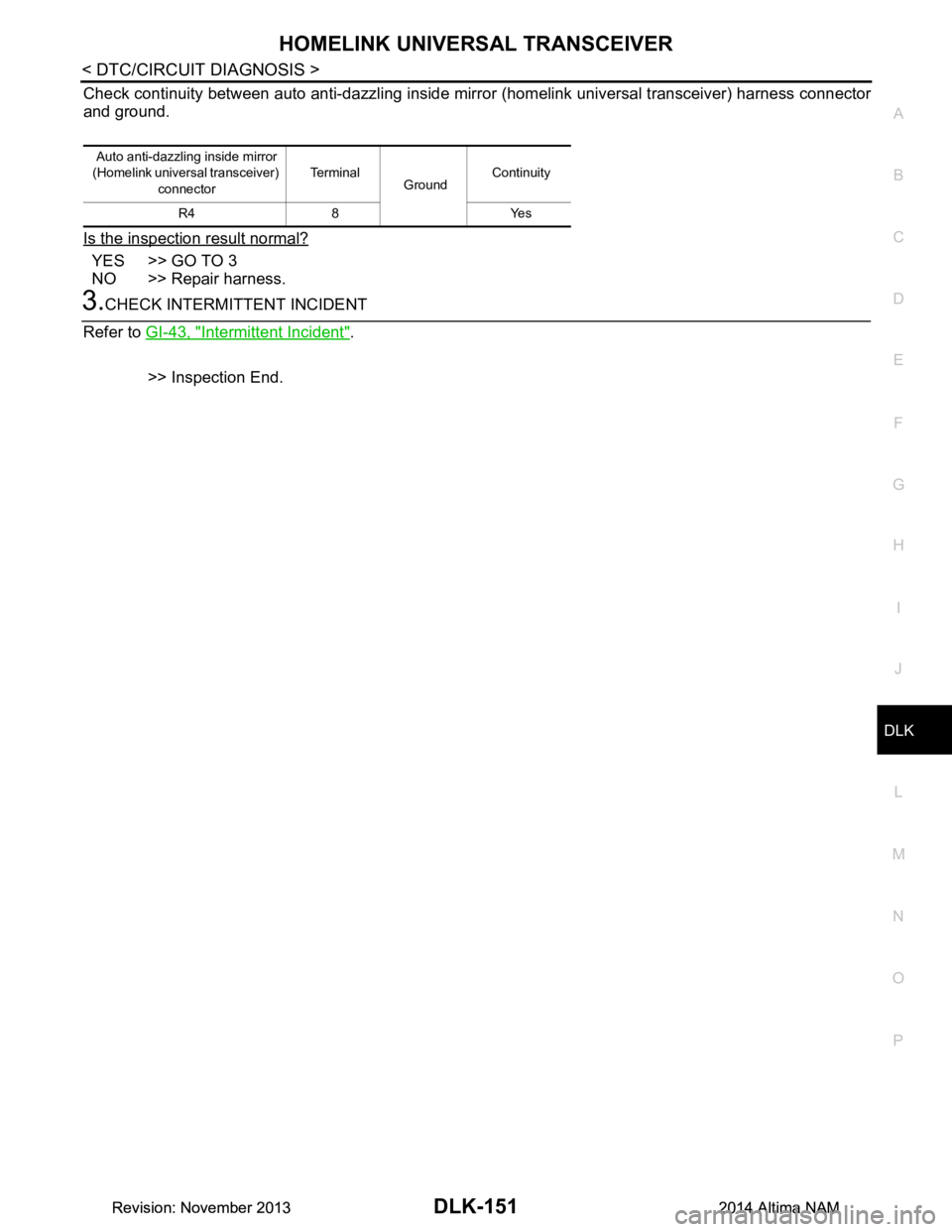
Check continuity between auto anti-dazzling inside mirr or (homelink universal transceiver) harness connector
and ground.
Is the inspection result normal?
YES >> GO TO 3
NO >> Repair harness.
3.CHECK INTERMITTENT INCIDENT
Refer to GI-43, "Intermittent Incident"
.
>> Inspection End.
Auto anti-dazzling inside mirror
(Homelink universal transceiver) connector Te r m i n a l
GroundContinuity
R4 8 Yes
Revision: November 20132014 Altima NAMRevision: November 20132014 Altima NAM
Page 2030 of 4801
![NISSAN TEANA 2014 Service Manual
EM-32
< REMOVAL AND INSTALLATION >[QR25DE]
INTAKE MANIFOLD
2. If studs were removed, install them and tighten to specification.
3. Tighten in numerical order as shown. CAUTION:
After tightening th NISSAN TEANA 2014 Service Manual
EM-32
< REMOVAL AND INSTALLATION >[QR25DE]
INTAKE MANIFOLD
2. If studs were removed, install them and tighten to specification.
3. Tighten in numerical order as shown. CAUTION:
After tightening th](/manual-img/5/57390/w960_57390-2029.png)
EM-32
< REMOVAL AND INSTALLATION >[QR25DE]
INTAKE MANIFOLD
2. If studs were removed, install them and tighten to specification.
3. Tighten in numerical order as shown. CAUTION:
After tightening the five bolts in the order shown, the 1, 6
position designates that the fi rst bolt tightened is to be
retightened to specification.
Electric Throttle Control Actuator
1. Install a new O-ring on the electric throttle control actuator. CAUTION:
Do not reuse electric throttl e control actuator O-ring.
2. Tighten the bolts of electric th rottle control actuator equally and
diagonally in several steps in numerical order as shown.
INSPECTION AFTER INSTALLATION
Make sure there are no fuel leaks at connections as follows:
1. Apply fuel pressure to fuel lines by turning ignition switch ON (with engine stopped). Then check for fuel leaks at connections.
NOTE:
Use mirrors for checking on connections out of the direct line of sight.
2. Start the engine and rev it up and check for fuel leaks at connections.
WARNING:
Do not touch engine immediately after stopping as engine is extremely hot.
Studs : 9.4 N·m (0.96 kg-m, 83 in-lb)
Bolts 1, 2, 3, 4, 5, 6 : 25.0 N·m (2.6 kg-m, 18 ft-lb)
Nuts 4, 5 : 25.0 N·m (2.6 kg-m, 18 ft-lb)
Bolt 7 : 45.0 N·m (4.6 kg-m, 33 ft-lb)
ALBIA0825GB
AWBIA1359ZZ
Revision: November 20132014 Altima NAM
Page 2042 of 4801
![NISSAN TEANA 2014 Service Manual
EM-44
< REMOVAL AND INSTALLATION >[QR25DE]
FUEL INJECTOR AND FUEL TUBE
c. Align center to insert quick connector straight onto fuel tube.
d. Insert fuel tube into quick connector (1) until the top s NISSAN TEANA 2014 Service Manual
EM-44
< REMOVAL AND INSTALLATION >[QR25DE]
FUEL INJECTOR AND FUEL TUBE
c. Align center to insert quick connector straight onto fuel tube.
d. Insert fuel tube into quick connector (1) until the top s](/manual-img/5/57390/w960_57390-2041.png)
EM-44
< REMOVAL AND INSTALLATION >[QR25DE]
FUEL INJECTOR AND FUEL TUBE
c. Align center to insert quick connector straight onto fuel tube.
d. Insert fuel tube into quick connector (1) until the top spool (B) on fuel tubes is inserted completely and the second level spool (C)
is positioned slightly below the quick connector bottom end.
CAUTION:
• Hold at position (A) as show n, when inserting the fuel
tube into the quick connector.
• Carefully align to center to avoid inclined insertion to pre-
vent damage to the O-ring inside the quick connector.
• Insert the fuel tube until you hear a “click” sound and
actually feel the engagement.
• To avoid misidentification of engagement with a similar
sound, be sure to perform the next step.
• Do not reuse O-ring.
e. Before clamping the fuel hose with the hose clamp, pull the quick connector hard by hand, holding at the
(A) position, as shown. Make sure it is completely engaged (connected) so that it does not come off of the
fuel tube.
NOTE:
Recommended pulling force is 50 N (5.1 kg, 11.2 lb).
f. Install quick connector cap (1) over fuel hose side (B) and fuel tube side (A).
NOTE:
Direct arrow mark on quick connector cap (1) to fuel hose side.
5. Installation of the remaining components is in the reverse order of removal.
INSPECTION AFTER INSTALLATION
Make sure there are no fuel leaks at connections as follows:
1. Apply fuel pressure to fuel lines by turning ignition switch ON (with engine stopped). Then check for fuel leaks at connections.
2. Start the engine and rev it up and check for fuel leaks at connections. • Perform procedures for “Throttle Valve Closed Posi tion Learning” after finishing repairs. Refer to EC-
178, "Work Procedure".
• If electric throttle control actuator is replaced, perform procedures for “Idle Air Volume Learning” after
finishing repairs. Refer to EC-179, "Work Procedure"
.
WARNING:
Do not touch engine immediately after stopping as engine is extremely hot.
NOTE:
Use mirrors for checking on connections out of the direct line of sight.
ALBIA0896GB
ALBIA0890GB
Revision: November 20132014 Altima NAM
Page 2148 of 4801
![NISSAN TEANA 2014 Service Manual
EM-150
< REMOVAL AND INSTALLATION >[VQ35DE]
INTAKE MANIFOLD
6. Loosen the bolts in the order as shown, and remove the intake
manifold.
INSPECTION AFTER REMOVAL
Surface Distortion
• Using straighte NISSAN TEANA 2014 Service Manual
EM-150
< REMOVAL AND INSTALLATION >[VQ35DE]
INTAKE MANIFOLD
6. Loosen the bolts in the order as shown, and remove the intake
manifold.
INSPECTION AFTER REMOVAL
Surface Distortion
• Using straighte](/manual-img/5/57390/w960_57390-2147.png)
EM-150
< REMOVAL AND INSTALLATION >[VQ35DE]
INTAKE MANIFOLD
6. Loosen the bolts in the order as shown, and remove the intake
manifold.
INSPECTION AFTER REMOVAL
Surface Distortion
• Using straightedge and feeler gauge, inspect the surface distortion of the intake manifold. Refer to EM-146, "Removal and Installa-
tion".
INSTALLATION
Installation is in the reverse order of removal. Fo llow the procedure below for specific tightening sequences
and procedures.
CAUTION:
Do not reuse intake manifold gaskets.
• Install intake manifold nuts and bolts in two steps in the numerical order as shown.
NOTE:
After installation, it is necessary to re-calibrate the electric throttle control actuator as follows:
1. Perform the "Throttle Valve Closed Position Learning" when harness connector of the electric throttle con-
trol actuator is disconnected. Refer to EC-682, "Work Procedure"
.
2. Perform the "Idle Air Volume Learning" when the electric throttle control actuator is replaced. Refer to EC-
683, "Work Procedure".
3. Install the quick connector. Refer to EM-163, "Removal and Installation"
.
INSPECTION AFTER INSTALLATION
Make sure there are no fuel leaks at the connections as follows:
1. Apply fuel pressure to fuel lines by turning ignition switch ON (with engine stopped). Then check for fuel leaks at connections.
2. Start the engine and rev it up and check for fuel leaks at connections. WARNING:
Do not touch engine immediately after stopping as engine is extremely hot.
NOTE:
Use mirrors for checking on connections out of the direct line of sight.
ALBIA0232ZZ
Standard : 0.1 mm (0.004 in)
WBIA0052E
Step 1 : 7.3 N·m (0.74 kg-m, 65 in-lb)
Step 2 : 25.5 N·m (2.6 kg-m, 19 ft-lb)
ALBIA0233ZZ
Revision: November 20132014 Altima NAM
Page 2165 of 4801
![NISSAN TEANA 2014 Service Manual
FUEL INJECTOR AND FUEL TUBEEM-167
< REMOVAL AND INSTALLATION > [VQ35DE]
C
D E
F
G H
I
J
K L
M A
EM
NP
O
b. Thinly apply new engine oil around fuel tube from tip end to spool end.
c. Align center to NISSAN TEANA 2014 Service Manual
FUEL INJECTOR AND FUEL TUBEEM-167
< REMOVAL AND INSTALLATION > [VQ35DE]
C
D E
F
G H
I
J
K L
M A
EM
NP
O
b. Thinly apply new engine oil around fuel tube from tip end to spool end.
c. Align center to](/manual-img/5/57390/w960_57390-2164.png)
FUEL INJECTOR AND FUEL TUBEEM-167
< REMOVAL AND INSTALLATION > [VQ35DE]
C
D E
F
G H
I
J
K L
M A
EM
NP
O
b. Thinly apply new engine oil around fuel tube from tip end to spool end.
c. Align center to insert quick connector straightly into fuel tube. • Insert quick connector (1) to fuel tube until top spool (2) is
completely inside quick connector, and 2nd level spool (3)
exposes right below quick connector.
CAUTION:
• Do not reuse O-ring.
• Hold (A) position as shown when inserting fuel tube into quick connector.
• Carefully align center to avoid inclined insertion to pre-
vent damage to O-ring inside quick connector.
• Insert until you hear a “click” sound and actually feel the engagement.
• To avoid misidentification of enga gement with a similar sound, be sure to perform the next step.
d. Pull quick connector by hand holding position. Check it is completely engaged (connected) so that it does
not come out from fuel tube.
e. Install quick connector cap (3) to quick connector.
• Install quick connector cap with arrow (A) on surface facing indirection of quick connector (fuel feed hose side).
CAUTION:
If quick connector cap cannot be installed smoothly, quick
connector may have not been installed correctly. Check
connection again.
f. Secure fuel feed hose to clamp of quick connector cap.
8. Installation of the remaining components is in the reverse order of removal.
INSPECTION AFTER INSTALLATION
Make sure there is no fuel leakage at connections as follows:
1. Apply fuel pressure to fuel lines by turning i gnition switch ON (with engine stopped). Then check for fuel
leaks at connections.
2. Start the engine and rev it up and check for fuel leaks at connections. WARNING:
Do not touch engine immediately after stopping as engine is extremely hot.
NOTE:
Use mirrors for checking on connections out of the direct line of sight.
• Perform procedures for “Throttle Valve Closed Position Learning” after finishing repairs. Refer to EC-
682, "Work Procedure".
• If electric throttle control actuator is replaced, perform procedures for “Idle Air Volume Learning” after
finishing repairs. Refer to EC-683, "Work Procedure"
.
(B) : Installed condition
: Upright insertion
(1) : Fuel feed hose
(2) : Fuel tube
(B) : Upper view
JPBIA0275ZZ
JPBIA0039ZZ
Revision: November 20132014 Altima NAM
Page 2269 of 4801

EXL-3
C
D E
F
G H
I
J
K
M A
B
EXL
N
O P
Description ..........................................................
..
119
Diagnosis Procedure .............................................119
PARKING, LICENSE PLATE AND TAIL
LAMPS ARE NOT TURNED ON .................... ..
120
Description .......................................................... ..120
Diagnosis Procedure .............................................120
BOTH SIDE FRONT FOG LAMPS ARE NOT
TURNED ON ................................................... ..
121
Description .......................................................... ..121
Diagnosis Procedure .............................................121
PERIODIC MAINTENANCE .......................122
HEADLAMP .................................................... ..122
Aiming Adjustment .............................................. ..122
FRONT FOG LAMP ..........................................124
Aiming Adjustment .............................................. ..124
REMOVAL AND INSTALLATION .............126
FRONT COMBINATION LAMP ...................... ..126
Exploded View - Xenon ....................................... ..126
Removal and Installation - Xenon .........................126
Bulb Replacement - Xenon ...................................127
Exploded View - Halogen ......................................128
Removal and Installation - Halogen ......................128
Bulb Replacement - Halo gen ................................129
TURN SIGNAL AND HAZARD WARNING
LAMPS ........................................................... ..
130
Removal and Installation .......................................130
Bulb Replacement ........ .........................................130
FRONT FOG LAMP ........................................ ..131
Removal and Installation .......................................131
Bulb Replacement ........ .........................................131
DOOR MIRROR TURN SIGNAL LAMP ......... ..133
Removal and Installation .......................................133
Bulb Replacement ........ .........................................133
HIGH-MOUNTED STOP LAMP ......................134
Removal and Installation ..................................... ..134
Bulb Replacement .................................................134
LICENSE PLATE LAMP .................................135
Removal and Installation .......................................135
Bulb Replacement .................................................135
REAR COMBINATION LAMP .........................136
Exploded View .......................................................136
Removal and Installation .......................................137
Bulb Replacement .................................................138
COMBINATION SWITCH ................................139
Exploded View .......................................................139
Removal and Installation .......................................139
HAZARD SWITCH ..........................................140
Removal and Installation .......................................140
OPTICAL SENSOR .........................................141
Removal and Installation .......................................141
UNIT DISASSEMBLY AND ASSEMBLY ..142
FRONT COMBINATION LAMP ......................142
Exploded View - Xenon ....................................... ..142
Disassembly and Assembly - Xenon .....................142
Exploded View - Halogen ......................................143
Disassembly and Assembly - Halogen ..................143
REAR COMBINATION LAMP .........................145
Exploded View - Non LED .....................................145
Disassembly and Assembly - Non LED .................145
Exploded View - LED .............................................146
Disassembly and Assembly - LED ........................146
SERVICE DATA AND SPECIFICATIONS
(SDS) ............... ...........................................
148
SERVICE DATA AND SPECIFICATIONS
(SDS) ...............................................................
148
Bulb Specifications .............................................. ..148
Revision: November 20132014 Altima NAMRevision: November 20132014 Altima NAM
Page 2372 of 4801

EXL-106
< DTC/CIRCUIT DIAGNOSIS >
TURN SIGNAL LAMP CIRCUIT
TURN SIGNAL LAMP CIRCUIT
DescriptionINFOID:0000000009463597
The BCM monitors inputs from the combination switch to determine when to activate the turn signals. The
BCM outputs voltage direction to the left and right turn signals during turn signal operation or both during haz-
ard warning operation. The BCM sends a turn signal indicator request to the combination meter via the CAN
communication lines.
The BCM performs the fast flasher operation (fail-safe) if any bulb or harness of the turn signal lamp circuit is
open.
NOTE:
Turn signal lamp blinks at normal speed when using the hazard warning lamp.
Component Function CheckINFOID:0000000009463598
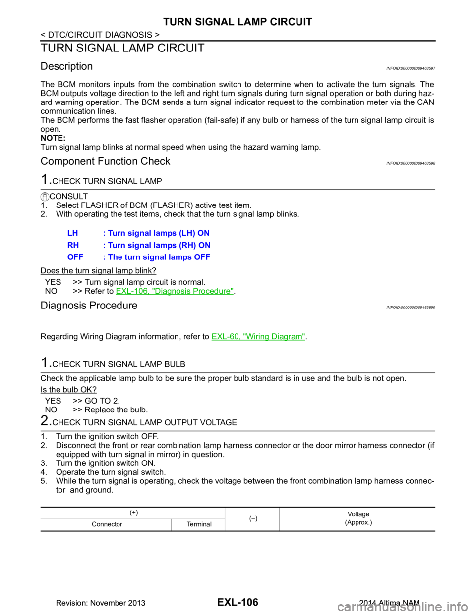
1.CHECK TURN SIGNAL LAMP
CONSULT
1. Select FLASHER of BCM (FLASHER) active test item.
2. With operating the test items, check that the turn signal lamp blinks.
Does the turn signal lamp blink?
YES >> Turn signal lamp circuit is normal.
NO >> Refer to EXL-106, "Diagnosis Procedure"
.
Diagnosis ProcedureINFOID:0000000009463599
Regarding Wiring Diagram information, refer to EXL-60, "Wiring Diagram".
1.CHECK TURN SIGNAL LAMP BULB
Check the applicable lamp bulb to be sure the proper bulb standard is in use and the bulb is not open.
Is the bulb OK?
YES >> GO TO 2.
NO >> Replace the bulb.
2.CHECK TURN SIGNAL LAMP OUTPUT VOLTAGE
1. Turn the ignition switch OFF.
2. Disconnect the front or rear combination lamp har ness connector or the door mirror harness connector (if
equipped with turn signal in mirror) in question.
3. Turn the ignition switch ON.
4. Operate the turn signal switch.
5. While the turn signal is operating, check the vo ltage between the front combination lamp harness connec-
tor and ground. LH : Turn signal lamps (LH) ON
RH : Turn signal lamps (RH) ON
OFF : The turn signal lamps OFF
(+) (− ) Vo l ta g e
(Approx.)
Connector Terminal
Revision: November 20132014 Altima NAMRevision: November 20132014 Altima NAM