Page 2647 of 4801

HEATING AND COOLING UNIT ASSEMBLYHA-41
< REMOVAL AND INSTALLATION >
C
D E
F
G H
J
K L
M A
B
HA
N
O P
HEATING AND COOLING UNIT ASSEMB LY : Removal and InstallationINFOID:0000000009463949
REMOVAL
1. Discharge the refrigerant. Refer to HA-23, "Recycle Refrigerant".
2. Drain the cooling system. Refer to CO-12, "Changing Engine Coolant"
.
3. Remove the instrument panel assembly. Refer to IP-15, "Removal and Installation"
.
4. Remove the steering column. Refer to ST-33, "Removal and Installation"
.
5. Remove the strut tower brace. Refer to FSU-19, "Exploded View"
.
6. Disconnect the low-pressure pipe from the expansion valve. CAUTION:
Cap or wrap the joint of the pipe with suitable ma terial such as vinyl tape to avoid the entry of air.
7. Disconnect the high-pressure pi pe from the expansion valve.
8. Disconnect the heater hoses from the heater core pipes.
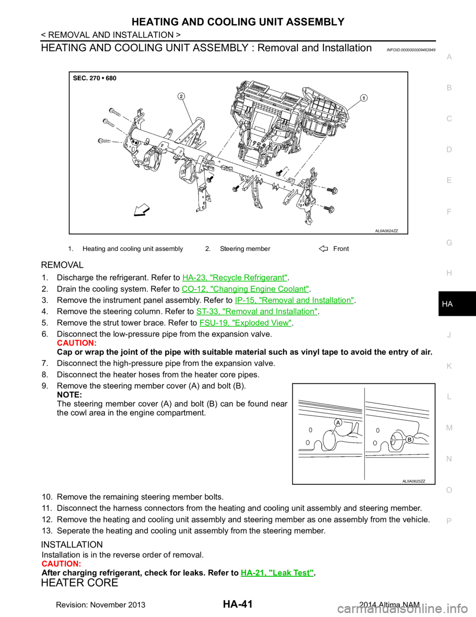
9. Remove the steering member cover (A) and bolt (B). NOTE:
The steering member cover (A) and bolt (B) can be found near
the cowl area in the engine compartment.
10. Remove the remaining steering member bolts.
11. Disconnect the harness connectors from the heati ng and cooling unit assembly and steering member.
12. Remove the heating and cooling unit assembly and steering member as one assembly from the vehicle.
13. Seperate the heating and cooling unit assembly from the steering member.
INSTALLATION
Installation is in the reverse order of removal.
CAUTION:
After charging refrigerant, check for leaks. Refer to HA-21, "Leak Test"
.
HEATER CORE
1. Heating and cooling unit assembly 2. Steering member Front
ALIIA0624ZZ
ALIIA0623ZZ
Revision: November 20132014 Altima NAM
Page 3166 of 4801
![NISSAN TEANA 2014 Service Manual
LU-16
< REMOVAL AND INSTALLATION >[QR25DE]
OIL COOLER
OIL COOLER
Exploded ViewINFOID:0000000009461035
Removal and InstallationINFOID:0000000009461036
WARNING:
Be careful not to burn yourself, as eng NISSAN TEANA 2014 Service Manual
LU-16
< REMOVAL AND INSTALLATION >[QR25DE]
OIL COOLER
OIL COOLER
Exploded ViewINFOID:0000000009461035
Removal and InstallationINFOID:0000000009461036
WARNING:
Be careful not to burn yourself, as eng](/manual-img/5/57390/w960_57390-3165.png)
LU-16
< REMOVAL AND INSTALLATION >[QR25DE]
OIL COOLER
OIL COOLER
Exploded ViewINFOID:0000000009461035
Removal and InstallationINFOID:0000000009461036
WARNING:
Be careful not to burn yourself, as engi ne oil and engine coolant may be hot.
NOTE:
When removing components such as hoses, tubes/lines, etc. , cap or plug openings to prevent fluid from spill-
ing.
REMOVAL
1. Remove RH front road wheel and tire. Refer to WT-55, "Adjustment".
2. Remove RH fender protector. Refer to EXT-26, "FENDER PROTECTOR : Removal and Installation"
.
3. Drain engine coolant by removing water drain plug on cylinder block and radiator drain plug. Refer to CO-
12, "Changing Engine Coolant".
4. Disconnect hoses from the oil cooler.
5. Remove oil cooler bolts in reverse numerical order.
6. Remove oil cooler.
7. Remove relief valve and O-rings.
INSTALLATION
Installation is in the reverse order of removal.
CAUTION:
1-5. Tightening sequence 6. O-ring 7. Relief Valve
8. Oil cooler A. To water hose
AWBIA1295GB
Revision: November 20132014 Altima NAM
Page 3182 of 4801
LU-32
< REMOVAL AND INSTALLATION >[VQ35DE]
OIL COOLER
OIL COOLER
Exploded ViewINFOID:0000000009461055
Removal and InstallationINFOID:0000000009461056
WARNING:
Be careful not to burn yourself, as the en gine oil and engine coolant may be hot.
CAUTION:
• When removing oil cooler, prepare a shop clot h to absorb any engine oil leaks or spills.
• Completely wipe off any engine oil that adheres to the engine and the vehicle.
NOTE:
AWBIA1199GB
1. Connector bolt 2. Copper gasket 3. Water drain plug
4. Water pipe 5. Bracket 6. Clamp
7. Water hose 8. Relief valve 9. O-ring
10. Oil cooler 11. Connector bolt 12. Oil filter
13. Water hose 14. Water pipe 15. Water hose
A. To water connector B. Refer to LU-27, "Removal and In-
stallation"
: Engine front Sealing point
Revision: November 20132014 Altima NAM
Page 3208 of 4801

MA-24
< PERIODIC MAINTENANCE >
ENGINE MAINTENANCE (VQ35DE)
REFILLING ENGINE COOLANT
1. Install the radiator drain plug. If the cooling system was drained completely, install the reservoir tank and
the cylinder block drain plugs.
• The radiator must be complete ly empty of coolant and water.
• Apply sealant to the threads of the cylinder block drain plug. Use Genuine High Performance
Thread Sealant or equivalent. Refer to GI-21, "Recommended Chemical Products and Sealants"
.
CAUTION:
Do not reuse copp er sealing washers.
2. If disconnected, reattach the upper radiator hose at the engine side.
3. Set the vehicle heater controls to the full HOT and heat er ON position. Turn the vehicle ignition ON with
the engine OFF as necessary to activate the heater mode.
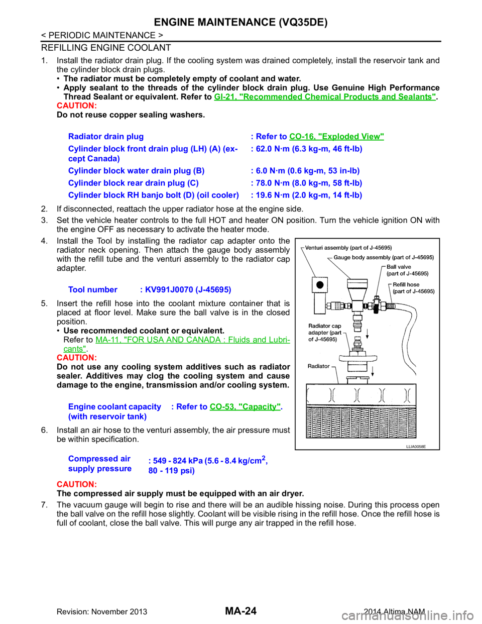
4. Install the Tool by installing the radiator cap adapter onto the radiator neck opening. Then attach the gauge body assembly
with the refill tube and the venturi assembly to the radiator cap
adapter.
5. Insert the refill hose into the coolant mixture container that is placed at floor level. Make sure the ball valve is in the closed
position.
• Use recommended coolant or equivalent.
Refer to MA-11, "FOR USA AND CANADA : Fluids and Lubri-
cants".
CAUTION:
Do not use any cooling system additives such as radiator
sealer. Additives may clog th e cooling system and cause
damage to the engine, transm ission and/or cooling system.
6. Install an air hose to the venturi assembly, the air pressure must be within specification.
CAUTION:
The compressed air supply must be equipped with an air dryer.
7. The vacuum gauge will begin to rise and there will be an audible hissing noise. During this process open the ball valve on the refill hose slightly. Coolant will be vi sible rising in the refill hose. Once the refill hose is
full of coolant, close the ball valve. This will purge any air trapped in the refill hose. Radiator drain plug : Refer to
CO-16, "Exploded View"
Cylinder block front drain plug (LH) (A) (ex-
cept Canada) : 62.0 N·m (6.3 kg-m, 46 ft-lb)
Cylinder block water drain plug (B) : 6.0 N·m (0.6 kg-m, 53 in-lb)
Cylinder block rear drain plug (C) : 78.0 N·m (8.0 kg-m, 58 ft-lb)
Cylinder block RH banjo bolt (D) (oil cooler) : 19.6 N·m (2.0 kg-m, 14 ft-lb)
Tool number : KV991J0070 (J-45695)
Engine coolant capacity
(with reservoir tank) : Refer to
CO-53, "Capacity"
.
Compressed air
supply pressure : 549 - 824 kPa (5.6 - 8.4 kg/cm
2,
80 - 119 psi)
LLIA0058E
Revision: November 20132014 Altima NAM
Page 3711 of 4801

RF-46
< REMOVAL AND INSTALLATION >
MOONROOF UNIT ASSEMBLY
d. Tighten glass lid bolts.NOTE:
First tighten left front bolt, then right rear bolt on glass lid to prevent uneven torque while tightening
remaining bolts.
e. After any adjustment, check moonroof operation and glass lid alignment.
Exploded ViewINFOID:0000000009461327
Removal and InstallationINFOID:0000000009461328
CAUTION:
• After installing either moonro of unit assembly or glass lid, check gap/height adjustments and opera-
tion to make sure there is no malfunction.
• Always work with a helper.
• Handle glass lid with care to prevent damage.
• When taking moonroof unit assembly out, use shop cloths to protect the headlining, seats and trim
from damage.
NOTE:
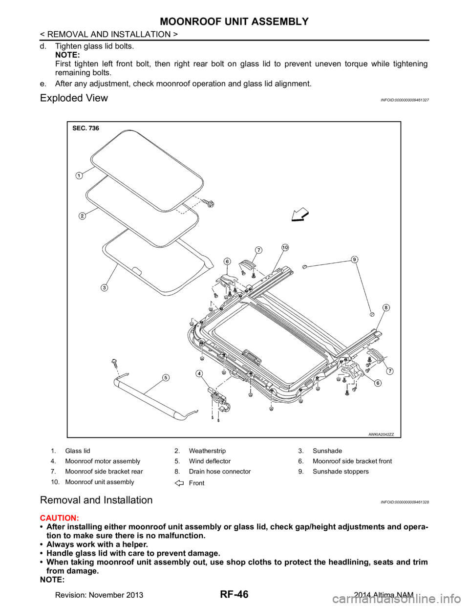
1. Glass lid 2. Weatherstrip 3. Sunshade
4. Moonroof motor assembly 5. Wind deflector 6. Moonroof side bracket front
7. Moonroof side bracket rear 8. Drain hose connector 9. Sunshade stoppers
10. Moonroof unit assembly Front
AWKIA2042ZZ
Revision: November 20132014 Altima NAMRevision: November 20132014 Altima NAM
Page 3712 of 4801

MOONROOF UNIT ASSEMBLYRF-47
< REMOVAL AND INSTALLATION >
C
D E
F
G H
I
J
L
M A
B
RF
N
O P
For easier and more accurate installation, always mark each point before removal.
REMOVAL
CAUTION:
Before servicing moonroof unit assembly, turn the ig nition switch off, disconnect both battery termi-
nals and wait at least three minutes.
1. Close glass lid.
2. Disconnect both the negative and positive battery terminal s, then wait at least three minutes. Refer to PG-
73, "Removal and Installation (Battery)".
3. Remove the headlining. Refer to INT-30, "Removal and Installation"
.
4. Disconnect drain hoses.
5. Disconnect the harness connector from the moonroof motor assembly.
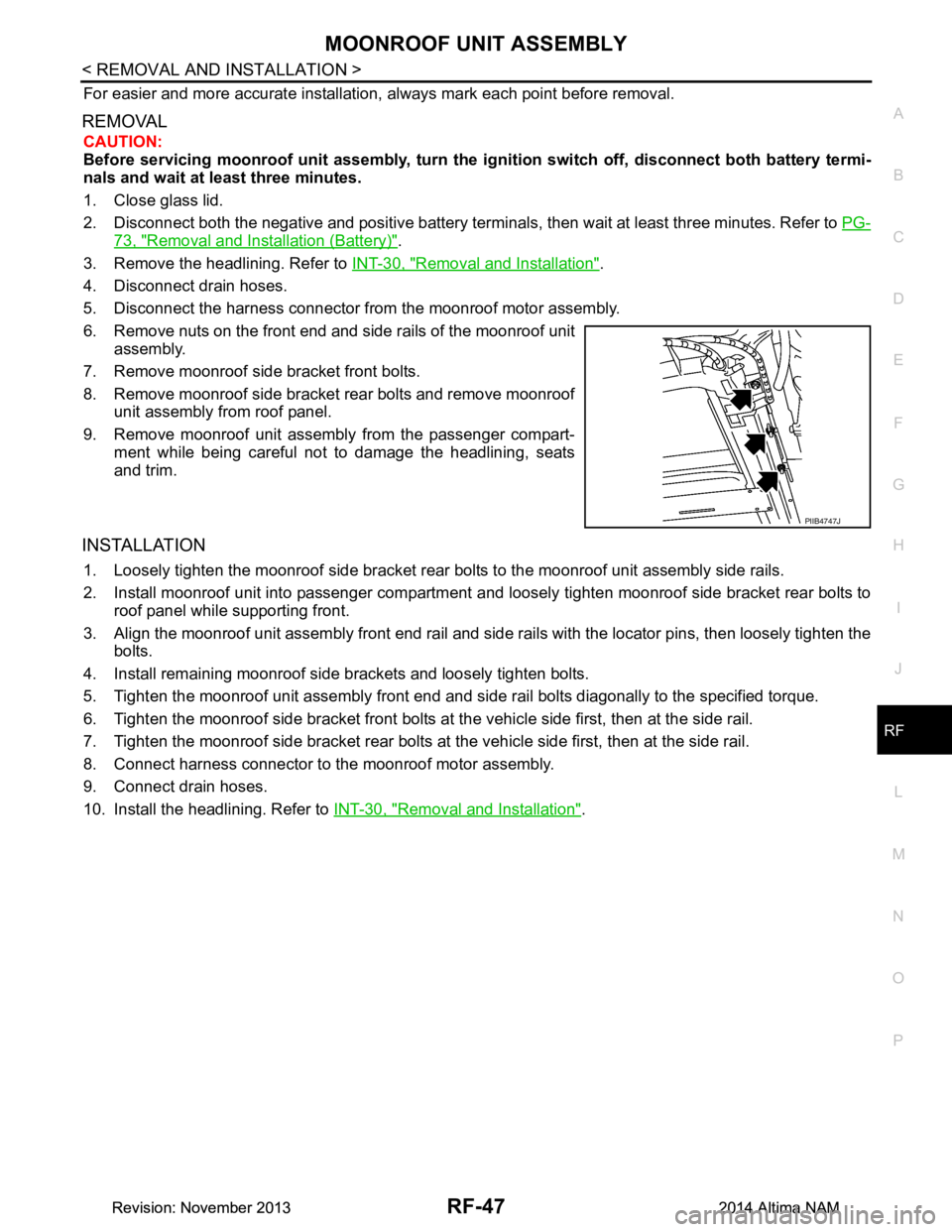
6. Remove nuts on the front end and side rails of the moonroof unit assembly.
7. Remove moonroof side bracket front bolts.
8. Remove moonroof side bracket rear bolts and remove moonroof unit assembly from roof panel.
9. Remove moonroof unit assembly from the passenger compart- ment while being careful not to damage the headlining, seats
and trim.
INSTALLATION
1. Loosely tighten the moonroof side bracket rear bolts to the moonroof unit assembly side rails.
2. Install moonroof unit into passenger compartment a nd loosely tighten moonroof side bracket rear bolts to
roof panel while supporting front.
3. Align the moonroof unit assembly front end rail and side rails with the locator pins, then loosely tighten the
bolts.
4. Install remaining moonroof side brackets and loosely tighten bolts.
5. Tighten the moonroof unit assembly front end and si de rail bolts diagonally to the specified torque.
6. Tighten the moonroof side bracket front bolts at the vehicle side first, then at the side rail.
7. Tighten the moonroof side bracket rear bolts at the vehicle side first, then at the side rail.
8. Connect harness connector to the moonroof motor assembly.
9. Connect drain hoses.
10. Install the headlining. Refer to INT-30, "Removal and Installation"
.
PIIB4747J
Revision: November 20132014 Altima NAMRevision: November 20132014 Altima NAM
Page 3716 of 4801
MOONROOF UNIT ASSEMBLYRF-51
< UNIT DISASSEMBLY AND ASSEMBLY >
C
D E
F
G H
I
J
L
M A
B
RF
N
O P
UNIT DISASSEMBLY AND ASSEMBLY
MOONROOF UNIT ASSEMBLY
Exploded ViewINFOID:0000000009461332
Disassembly and AssemblyINFOID:0000000009461333
DISASSEMBLY
1. Remove the moonroof unit assembly. Refer to RF-46, "Removal and Installation".
2. Remove the sunshade stoppers (LH/RH) from the moonroof unit assembly side rails.
3. Remove sunshade from the rear end of moonroof unit assembly.
4. Remove glass lid bolts on each side.
5. Remove glass lid from moonroof unit assembly.
6. Remove the wind deflector screws (one from each side).
1. Glass lid 2. Weatherstrip 3. Sunshade
4. Moonroof motor assembly 5. Wind deflector 6. Moonroof side bracket front
7. Moonroof side bracket rear 8. Drain hose connector 9. Sunshade stoppers
7. Moonroof side bracket rear Front
AWKIA2042ZZ
Revision: November 20132014 Altima NAMRevision: November 20132014 Altima NAM
Page 4141 of 4801
ST-38
< REMOVAL AND INSTALLATION >
POWER STEERING OIL PUMP
POWER STEERING OIL PUMP
Exploded ViewINFOID:0000000009461274
Removal and InstallationINFOID:0000000009461275
NOTE:
When removing components such as hoses, tubes/lines, etc. , cap or plug openings to prevent fluid from spill-
ing.
REMOVAL
1. Remove the power steering oil pump cover (1).
2. Drain power steering fluid. Refer to ST-30, "Draining and Refilling"
.
3. Remove the bolt from the power steering pressure line bracket.
1. Power steering reservoir cap 2. Power steering oil pump assembly 3. Low pressure piping
4. High pressure piping Front
ALGIA0145GB
ALGIA0132ZZ
Revision: November 20132014 Altima NAMRevision: November 20132014 Altima NAM