2014 NISSAN TEANA oil type
[x] Cancel search: oil typePage 2086 of 4801
![NISSAN TEANA 2014 Service Manual
EM-88
< UNIT DISASSEMBLY AND ASSEMBLY >[QR25DE]
CYLINDER BLOCK
Disassembly and Assembly
INFOID:0000000009460510
CAUTION:
Apply new engine oil to parts marked in illustration before installation.
NO NISSAN TEANA 2014 Service Manual
EM-88
< UNIT DISASSEMBLY AND ASSEMBLY >[QR25DE]
CYLINDER BLOCK
Disassembly and Assembly
INFOID:0000000009460510
CAUTION:
Apply new engine oil to parts marked in illustration before installation.
NO](/manual-img/5/57390/w960_57390-2085.png)
EM-88
< UNIT DISASSEMBLY AND ASSEMBLY >[QR25DE]
CYLINDER BLOCK
Disassembly and Assembly
INFOID:0000000009460510
CAUTION:
Apply new engine oil to parts marked in illustration before installation.
NOTE:
The following procedures explain how to disassem ble the engine with the engine stand fastened to the bell
housing. Some steps may be different if using a different type of engine stand.
DISASSEMBLY
1. Remove the engine and transaxle as an assembly from the vehicle, and separate the transaxle from the
engine. Refer to EM-84, "Removal and Installation"
.
2. Remove the drive plate. Hold the crankshaft using Tool (A) and use a suitable tool to remove the bolts.
3. Remove pilot converter using Tool.
4. Remove the rear oil seal. Refer to EM-72, "Removal and Installation of Rear Oil Seal"
.
5. Mount the engine on a suitable engine stand (A). CAUTION:
• Use an engine stand that has a load capacity large
enough for supporting the engine weight [approximately
135 kg (298 lb) or more].
• Before removing the hanging chains, check the engine
stand is stable and there is no risk of overturning.
NOTE:
The figure shows an example of widely used engine stand (A)
that can support mating surface of transaxle with drive plate
removed.
• Remove the following parts if the engine stand load capacity is not adequate, to reduce the potential risk of overturning stand:
- Intake manifold. Refer to EM-30, "Removal and Installation"
.
- Exhaust manifold. Refer to EM-33, "Removal and Installation"
.
- Rocker cover. Refer to EM-45, "Removal and Installation"
.
6. Drain any remaining engine oil and coolant from the engine.
7. Remove the exhaust manifold and three way catalyst assembly. Refer to EM-33, "Removal and Installa-
tion".
8. Remove the intake manifold and fuel tube assembly. Refer to EM-30, "Removal and Installation"
.
28. Oil level gauge guide 29. Oil level gauge 30. O-ring
A. Follow assembly procedure
Tool Number : KV11105210 (J-44716)
PBIC3226J
Tool Number : ST16610001 (J-23907)
WBIA0483E
PBIC3227J
Revision: November 20132014 Altima NAM
Page 2129 of 4801
![NISSAN TEANA 2014 Service Manual
NOISE, VIBRATION, AND HARSHNESS (NVH) TROUBLESHOOTINGEM-131
< SYSTEM DESCRIPTION > [VQ35DE]
C
D E
F
G H
I
J
K L
M A
EM
NP
OUse the Chart Below to Help You
Find the Cause of the SymptomINFOID:000000 NISSAN TEANA 2014 Service Manual
NOISE, VIBRATION, AND HARSHNESS (NVH) TROUBLESHOOTINGEM-131
< SYSTEM DESCRIPTION > [VQ35DE]
C
D E
F
G H
I
J
K L
M A
EM
NP
OUse the Chart Below to Help You
Find the Cause of the SymptomINFOID:000000](/manual-img/5/57390/w960_57390-2128.png)
NOISE, VIBRATION, AND HARSHNESS (NVH) TROUBLESHOOTINGEM-131
< SYSTEM DESCRIPTION > [VQ35DE]
C
D E
F
G H
I
J
K L
M A
EM
NP
OUse the Chart Below to Help You
Find the Cause of the SymptomINFOID:0000000009460525
1. Locate the area where noise occurs.
2. Confirm the type of noise.
3. Specify the operating condition of engine.
4. Check specified noise source. Repair or replace the identified part as necessary.
A: Closely related B: Related C: Sometimes related —: Not related7.
Timing chain and chain
tensioner noise 8. Drive belt noise (Sticking/Slipping) 9. Tappet noise
A. Valve B. Valve mechanism C. Rotation mechanism
D. Drive belt E. Timing chain
Location of noise Type of
noise Operating condition of engine
Source of noise Check item Refer-
ence page
Before
warm- up After
warm- up When
start- ing When
idling When
racing While
driving
Top of en-
gine
Rocker
cover
Cylinder
head Ticking or
clicking CA—AB— Tappet
noise Valve clearance
EM-138
Rattle C A — A B C Camshaft
bearing
noise Camshaft journal clear-
ance
Camshaft runout EM-194
Crank-
shaft pul-
ley
Cylinder
block
(Side of
engine)
Oil pan Slap or
knock —A—BB— Piston pin
noise Piston and piston pin
clearance
Connecting rod bushing
clearance EM-142
Slap or
rap A——BBA Piston
slap noise Piston-to-bore clear-
ance
Piston ring side clear-
ance
Piston ring end gap
Connecting rod bend
and torsion EM-224
Knock A B C B B B
Connect-
ing rod
bearing
noise Connecting rod bushing
clearance (Small end)
Connecting rod bearing
clearance (Big end) EM-224
Knock A B — A B C
Main bear-
ing noise Main bearing oil clear-
ance
Crankshaft runout EM-224
Front of
engine
Timing
chain cov-
er Tapping or
ticking AA—BBB Timing
chain and
chain ten-
sioner
noise Timing chain cracks
and wear
Timing chain tensioner
operation EM-182
Front of
engine Squeak-
ing or fizz-
ing AB—B—C Drive belts
(Sticking
or slip-
ping) Drive belts deflection
EM-134
CreakingA B ABAB Drive belts
(Slipping) Idler pulley bearing op-
eration
Squall
Creak AB—BAB Water
pump
noise Water pump operation
CO-44
Revision: November 20132014 Altima NAM
Page 2245 of 4801
![NISSAN TEANA 2014 Service Manual
SERVICE DATA AND SPECIFICATIONS (SDS)EM-247
< SERVICE DATA AND SPECIFICATIONS (SDS) [VQ35DE]
C
D E
F
G H
I
J
K L
M A
EM
NP
O
Spark PlugINFOID:0000000009460586
SPARK PLUG
Unit: mm (in)
*: Always che NISSAN TEANA 2014 Service Manual
SERVICE DATA AND SPECIFICATIONS (SDS)EM-247
< SERVICE DATA AND SPECIFICATIONS (SDS) [VQ35DE]
C
D E
F
G H
I
J
K L
M A
EM
NP
O
Spark PlugINFOID:0000000009460586
SPARK PLUG
Unit: mm (in)
*: Always che](/manual-img/5/57390/w960_57390-2244.png)
SERVICE DATA AND SPECIFICATIONS (SDS)EM-247
< SERVICE DATA AND SPECIFICATIONS (SDS) [VQ35DE]
C
D E
F
G H
I
J
K L
M A
EM
NP
O
Spark PlugINFOID:0000000009460586
SPARK PLUG
Unit: mm (in)
*: Always check with the Parts Department for the latest parts information.
Intake Manifold INFOID:0000000009460587
INTAKE MANIFOLD
Unit: mm (in)
Exhaust ManifoldINFOID:0000000009460588
EXHAUST MANIFOLD
Unit: mm (in)
CamshaftINFOID:0000000009460589
CAMSHAFT
Unit: mm (in)
Tension of drive belt Belt tension is not necessary, as it is automatically adjusted by drive belt auto-tensioner.
Make
DENSO
Standard type* FXE22HR11
Gap Standard 1.1 (0.043)
Items Limit
Surface distortion Intake manifold 0.1 (0.004)
Items Limit
Surface distortion Exhaust manifold 0.3 (0.012)
Items Standard Limit
Camshaft journal oil clearance No. 1 0.045 - 0.086 (0.0018 - 0.0034)
0.15 (0.0059)
No. 2, 3, 4 0.035 - 0.076 (0.0014 - 0.0030)
Camshaft bracket inner diameter No. 1 26.000 - 26.021 (1.0236 - 1.0244) —
No. 2, 3, 4 23.500 - 23.521 (0.9252 - 0.9260) —
Camshaft journal diameter No. 1 25.935 - 25.955 (1.0211 - 1.0218) —
No. 2, 3, 4 23.445 - 23.465 (0.9230 - 0.9238) —
Camshaft end play 0.115 - 0.188 (0.0045 - 0.0074) 0.24 (0.0094)
Camshaft cam height (A) Intake 45.475 - 45.665 (1.7904 - 1.7978)
0.2 (0.008)*
1
Exhaust 45.485 - 45.675 (1.7907 - 1.7982)0.2 (0.008)*1
Camshaft runout [TIR*2]Less than 0.02 (0.0008) 0.05 (0.0020)
Camshaft sprocket runout [TIR*
2] Less than 0.15 (0.0059) —
Revision: November 20132014 Altima NAM
Page 2270 of 4801
EXL-4
< PRECAUTION >
PRECAUTIONS
PRECAUTION
PRECAUTIONS
Precaution for Supplemental Restraint System (SRS) "AIR BAG" and "SEAT BELT
PRE-TENSIONER"
INFOID:0000000009951582
The Supplemental Restraint System such as “A IR BAG” and “SEAT BELT PRE-TENSIONER”, used along
with a front seat belt, helps to reduce the risk or severi ty of injury to the driver and front passenger for certain
types of collision. Information necessary to service the system safely is included in the SR and SB section of
this Service Manual.
WARNING:
• To avoid rendering the SRS inopera tive, which could increase the risk of personal injury or death in
the event of a collision which would result in air bag inflation, all maintenance must be performed by
an authorized NISS AN/INFINITI dealer.
• Improper maintenance, including in correct removal and installation of the SRS, can lead to personal
injury caused by unintent ional activation of the system. For re moval of Spiral Cable and Air Bag
Module, see the SR section.
• Do not use electrical test equipmen t on any circuit related to the SRS unless instructed to in this
Service Manual. SRS wiring harn esses can be identified by yellow and/or orange harnesses or har-
ness connectors.
PRECAUTIONS WHEN USING POWER TOOLS (AIR OR ELECTRIC) AND HAMMERS
WARNING:
• When working near the Airbag Diagnosis Sensor Unit or other Airbag System sensors with the Igni-
tion ON or engine running, DO NOT use air or electri c power tools or strike near the sensor(s) with a
hammer. Heavy vibration could activate the sensor( s) and deploy the air bag(s), possibly causing
serious injury.
• When using air or electric power tools or hammers , always switch the Ignition OFF, disconnect the
battery and wait at least three minutes before performing any service.
General precautions fo r service operationsINFOID:0000000009463538
• Do not work with wet hands.
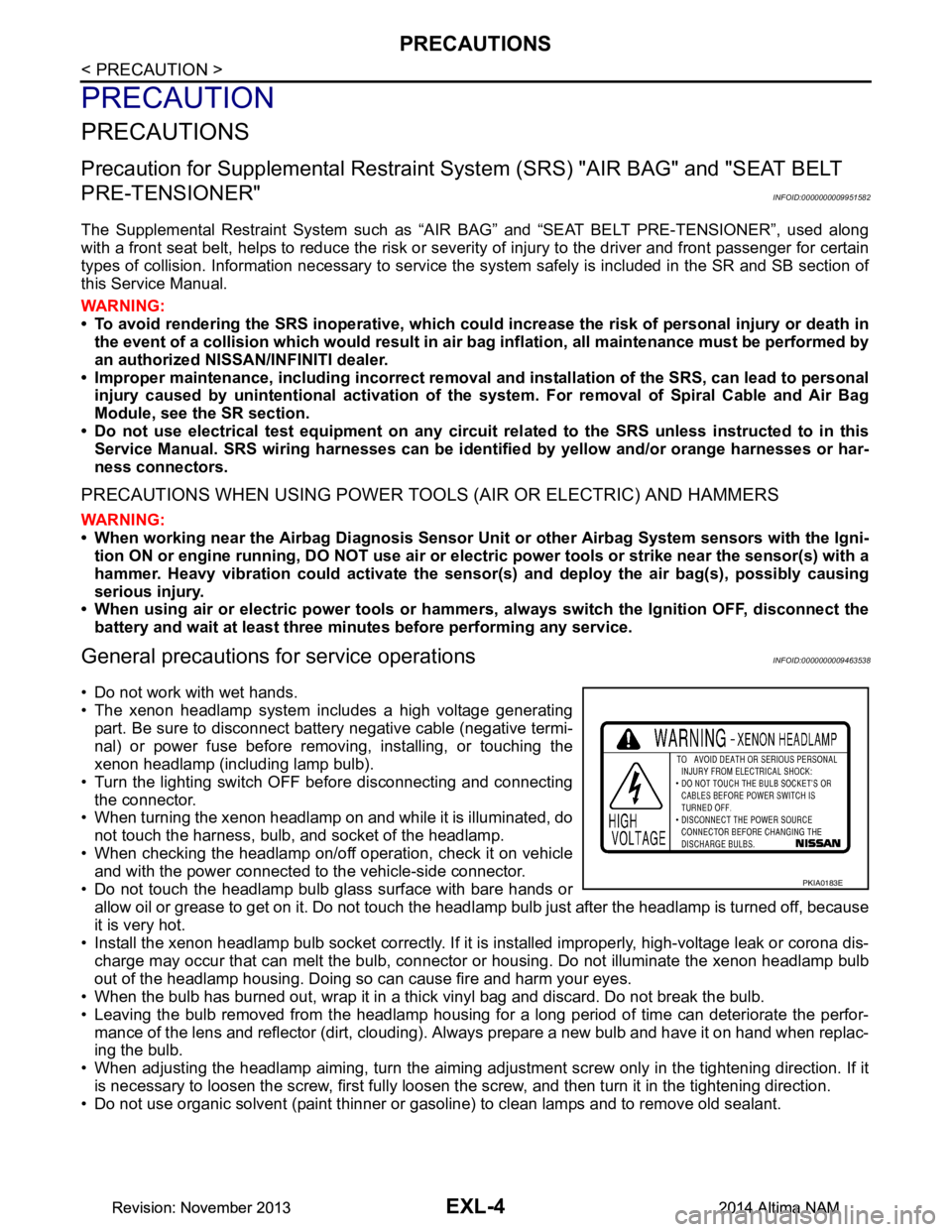
• The xenon headlamp system includes a high voltage generating
part. Be sure to disconnect batte ry negative cable (negative termi-
nal) or power fuse before removing, installing, or touching the
xenon headlamp (including lamp bulb).
• Turn the lighting switch OFF before disconnecting and connecting the connector.
• When turning the xenon headlamp on and while it is illuminated, do
not touch the harness, bulb, and socket of the headlamp.
• When checking the headlamp on/off operation, check it on vehicle and with the power connected to the vehicle-side connector.
• Do not touch the headlamp bulb glass surface with bare hands or allow oil or grease to get on it. Do not touch the headl amp bulb just after the headlamp is turned off, because
it is very hot.
• Install the xenon headlamp bulb socket co rrectly. If it is installed improperly, high-voltage leak or corona dis-
charge may occur that can melt the bulb, connector or housing. Do not illuminate the xenon headlamp bulb
out of the headlamp housing. Doing so can cause fire and harm your eyes.
• When the bulb has burned out, wrap it in a thick vinyl bag and discard. Do not break the bulb.
• Leaving the bulb removed from the headlamp housing for a long period of time can deteriorate the perfor- mance of the lens and reflector (dirt, clouding). Al ways prepare a new bulb and have it on hand when replac-
ing the bulb.
• When adjusting the headlamp aiming, turn the aiming adjus tment screw only in the tightening direction. If it
is necessary to loosen the screw, first fully loosen the screw, and then turn it in the tightening direction.
• Do not use organic solvent (paint thinner or gasoline) to clean lamps and to remove old sealant.
PKIA0183E
Revision: November 20132014 Altima NAMRevision: November 20132014 Altima NAM
Page 2275 of 4801
SYSTEMEXL-9
< SYSTEM DESCRIPTION >
C
D E
F
G H
I
J
K
M A
B
EXL
N
O P
SYSTEM
HEADLAMP SYSTEM
HEADLAMP SYSTEM : System DiagramINFOID:0000000009463543
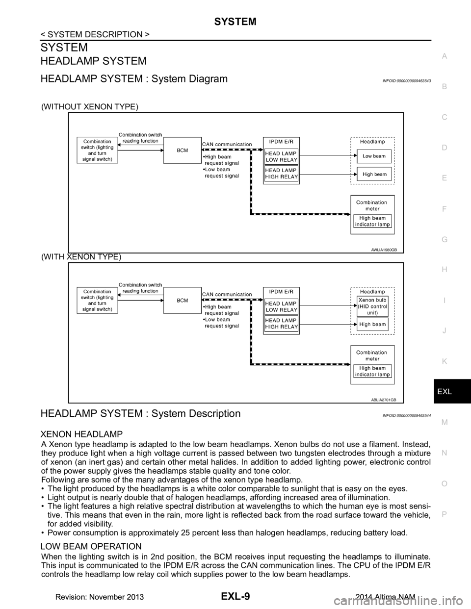
(WITHOUT XENON TYPE)
(WITH XENON TYPE)
HEADLAMP SYSTEM : System DescriptionINFOID:0000000009463544
XENON HEADLAMP
A Xenon type headlamp is adapted to the low beam headlamps. Xenon bulbs do not use a filament. Instead,
they produce light when a high voltage current is pa ssed between two tungsten electrodes through a mixture
of xenon (an inert gas) and certain other metal halides. In addition to added lighting power, electronic control
of the power supply gives the headlamps stable quality and tone color.
Following are some of the many advantages of the xenon type headlamp.
• The light produced by the headlamps is a white color comparable to sunlight that is easy on the eyes.
• Light output is nearly double that of halogen headl amps, affording increased area of illumination.
• The light features a high relative spectral distributi on at wavelengths to which the human eye is most sensi-
tive. This means that even in the rain, more light is reflected back from the road surface toward the vehicle,
for added visibility.
• Power consumption is approximately 25 percent less than halogen headlamps, reducing battery load.
LOW BEAM OPERATION
When the lighting switch is in 2nd position, the BCM receives input requesting the headlamps to illuminate.
This input is communicated to the IPDM E/R across the CAN communication lines. The CPU of the IPDM E/R
controls the headlamp low relay coil which supplies power to the low beam headlamps.
AWLIA1980GB
ABLIA2701GB
Revision: November 20132014 Altima NAMRevision: November 20132014 Altima NAM
Page 2390 of 4801
EXL-124
< PERIODIC MAINTENANCE >
FRONT FOG LAMP
FRONT FOG LAMP
Aiming AdjustmentINFOID:0000000009463618
PREPARATION BEFORE ADJUSTING
The fog lamp is a semi-sealed beam type which uses a replaceable halogen bulb. Before performing aiming
adjustment procedure, check the following:
• Ensure all tires are inflated to correct pressure.
• Place vehicle and screen on level surface.
• Ensure there is no load in vehicle other than the driver (or equivalent weight placed in driver's position).
• Coolant and engine oil filled to correct level, and fuel tank full.
• Remove cargo and/or luggage to maintain an unloaded vehicle condition.
• Confirm spare tire, jack and tools are properly stowed.
• Carefully wipe off any dirt from headlamp lens. CAUTION:
Do not use organic solvent (thinner, gasoline etc.)
• Place a driver or equivalent weight of 68.5 kg (150 lb) on the driver seat.
• By hand, bounce the front and rear of the vehicle to settle the suspension and eliminate any static load.
• Place the front tires in the straight ahead position.
• Aim each headlamp individually and ensure other headlamp beam pattern is blocked from screen.
NOTE:
• For headlamp aiming details, refer to regulations in your area.
• By regulation, no means for horizontal aim adjustment is provided from the factory; only vertical aim is
adjustable.
• Use adjusting screw to perform aiming adjustment.
• Perform headlamp aiming if:
- The vehicle front body has been repaired.
- The front combination lamp has been removed or replaced.
- Any outfitting has been installed.
- The vehicle’s standard load condition has been substantially increased.
Aiming Adjustment Procedure
1. Place the screen. NOTE:
• Stop the vehicle facing the wall.
• Place the board on a plain road vertically.
2. Face the vehicle with the screen. Maintain 7.62 m (25.0 ft) between the front fog lamp center and the
screen.
3. Start the engine. Turn the front fog lamp ON. NOTE:
Shut off the headlamp light with the board to prevent from illuminating the adjustment screen.
CAUTION:
Do not cover the lens surface with a tape etc. The lens is made of resin.
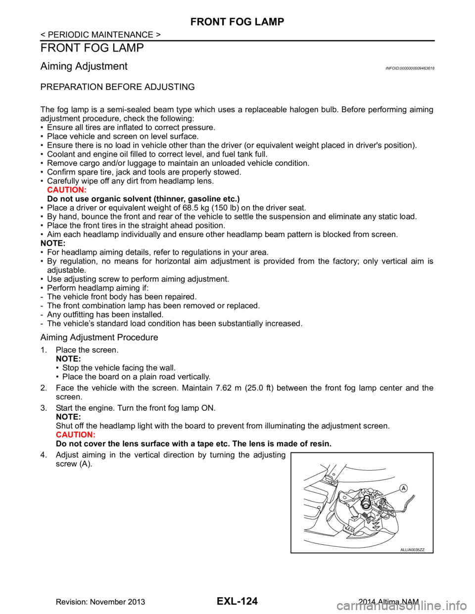
4. Adjust aiming in the vertical direction by turning the adjusting screw (A).
ALLIA0035ZZ
Revision: November 20132014 Altima NAMRevision: November 20132014 Altima NAM
Page 2417 of 4801
PRECAUTIONSEXT-3
< PRECAUTION >
C
D E
F
G H
I
J
L
M A
B
EXT
N
O P
PRECAUTION
PRECAUTIONS
Precaution for Supplemental Restraint System (SRS) "AIR BAG" and "SEAT BELT
PRE-TENSIONER"
INFOID:0000000009951571
The Supplemental Restraint System such as “A IR BAG” and “SEAT BELT PRE-TENSIONER”, used along
with a front seat belt, helps to reduce the risk or severi ty of injury to the driver and front passenger for certain
types of collision. Information necessary to service t he system safely is included in the SR and SB section of
this Service Manual.
WARNING:
• To avoid rendering the SRS inoper ative, which could increase the risk of personal injury or death in
the event of a collision which would result in air bag inflation, all maintenance must be performed by
an authorized NISSAN/INFINITI dealer.
• Improper maintenance, including in correct removal and installation of the SRS, can lead to personal
injury caused by unintentional act ivation of the system. For removal of Spiral Cable and Air Bag
Module, see the SR section.
• Do not use electrical test equipm ent on any circuit related to the SRS unless instructed to in this
Service Manual. SRS wiring harnesses can be identi fied by yellow and/or orange harnesses or har-
ness connectors.
PRECAUTIONS WHEN USING POWER TOOLS (AIR OR ELECTRIC) AND HAMMERS
WARNING:
• When working near the Airbag Diagnosis Sensor Un it or other Airbag System sensors with the Igni-
tion ON or engine running, DO NOT use air or el ectric power tools or strike near the sensor(s) with a
hammer. Heavy vibration could activate the sensor( s) and deploy the air bag(s), possibly causing
serious injury.
• When using air or electric power tools or hammers , always switch the Ignition OFF, disconnect the
battery and wait at least three mi nutes before performing any service.
Precaution for Procedure without Cowl Top CoverINFOID:0000000009460986
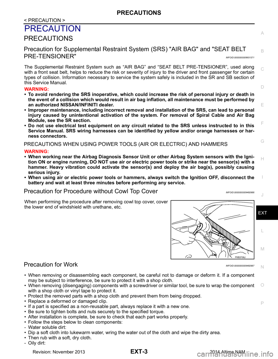
When performing the procedure after removing cowl top cover, cover
the lower end of windshield with urethane, etc.
Precaution for WorkINFOID:0000000009460987
• When removing or disassembling each component, be ca reful not to damage or deform it. If a component
may be subject to interference, be sure to protect it with a shop cloth.
• When removing (disengaging) components with a screwdriver or similar tool, be sure to wrap the component with a shop cloth or vinyl tape to protect it.
• Protect the removed parts with a shop cloth and prevent them from being dropped.
• Replace a deformed or damaged clip.
• If a part is specified as a non-reusabl e part, always replace it with a new one.
• Be sure to tighten bolts and nuts securely to the specified torque.
• After installation is complete, be sure to check that each part works properly.
• Follow the steps below to clean components:
- Water soluble dirt:
• Dip a soft cloth into lukewarm water, wring the water out of the cloth and wipe the dirty area.
• Then rub with a soft, dry cloth.
-Oily dirt:
PIIB3706J
Revision: November 20132014 Altima NAM
Page 2503 of 4801
FSU-2
< PRECAUTION >
PRECAUTIONS
PRECAUTION
PRECAUTIONS
Precaution for Supplemental Restraint System (SRS) "AIR BAG" and "SEAT BELT
PRE-TENSIONER"
INFOID:0000000009951705
The Supplemental Restraint System such as “A IR BAG” and “SEAT BELT PRE-TENSIONER”, used along
with a front seat belt, helps to reduce the risk or severi ty of injury to the driver and front passenger for certain
types of collision. Information necessary to service the system safely is included in the SR and SB section of
this Service Manual.
WARNING:
• To avoid rendering the SRS inopera tive, which could increase the risk of personal injury or death in
the event of a collision which would result in air bag inflation, all maintenance must be performed by
an authorized NISS AN/INFINITI dealer.
• Improper maintenance, including in correct removal and installation of the SRS, can lead to personal
injury caused by unintent ional activation of the system. For re moval of Spiral Cable and Air Bag
Module, see the SR section.
• Do not use electrical test equipmen t on any circuit related to the SRS unless instructed to in this
Service Manual. SRS wiring harn esses can be identified by yellow and/or orange harnesses or har-
ness connectors.
PRECAUTIONS WHEN USING POWER TOOLS (AIR OR ELECTRIC) AND HAMMERS
WARNING:
• When working near the Airbag Diagnosis Sensor Unit or other Airbag System sensors with the Igni-
tion ON or engine running, DO NOT use air or electri c power tools or strike near the sensor(s) with a
hammer. Heavy vibration could activate the sensor( s) and deploy the air bag(s), possibly causing
serious injury.
• When using air or electric power tools or hammers , always switch the Ignition OFF, disconnect the
battery and wait at least three minutes before performing any service.
General PrecautionsINFOID:0000000009460620
• When installing rubber bushings, the final tightening mu st be carried out under unladen conditions with tires
on ground. Oil might shorten the life of rubber bushings. Be sure to wipe off any spilled oil.
- Unladen conditions mean that fuel, engine coolant and lubricant are full. Spare tire, jack, hand tools and mats are in designated positions.
• After servicing suspension parts, be sure to check wheel alignment.
• Self-lock nuts are not reusable. Always use new ones when installing. Since new self-lock nuts are pre-oiled,
tighten as they are.
Precaution for Procedure without Cowl Top CoverINFOID:0000000009460621
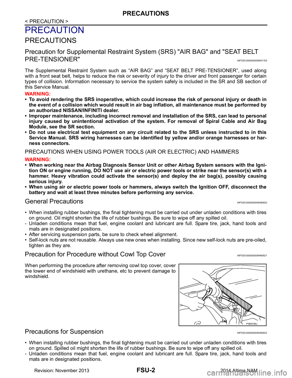
When performing the procedure after removing cowl top cover, cover
the lower end of windshield with urethane, etc to prevent damage to
windshield.
Precautions for SuspensionINFOID:0000000009460622
• When installing rubber bushings, the final tightening mu st be carried out under unladen conditions with tires
on ground. Spilled oil might shorten the life of rubber bushings. Be sure to wipe off any spilled oil.
- Unladen conditions mean that fuel, engine coolant and lubricant are full. Spare tire, jack, hand tools and mats are in designated positions.
PIIB3706J
Revision: November 20132014 Altima NAM