2014 NISSAN TEANA dimensions
[x] Cancel search: dimensionsPage 2213 of 4801
![NISSAN TEANA 2014 Service Manual
CYLINDER HEADEM-215
< REMOVAL AND INSTALLATION > [VQ35DE]
C
D E
F
G H
I
J
K L
M A
EM
NP
O
5. Using a valve guide reamer, apply a reamer finish to the valve
guide.
VALVE SEAT CONTACT
• After confir NISSAN TEANA 2014 Service Manual
CYLINDER HEADEM-215
< REMOVAL AND INSTALLATION > [VQ35DE]
C
D E
F
G H
I
J
K L
M A
EM
NP
O
5. Using a valve guide reamer, apply a reamer finish to the valve
guide.
VALVE SEAT CONTACT
• After confir](/manual-img/5/57390/w960_57390-2212.png)
CYLINDER HEADEM-215
< REMOVAL AND INSTALLATION > [VQ35DE]
C
D E
F
G H
I
J
K L
M A
EM
NP
O
5. Using a valve guide reamer, apply a reamer finish to the valve
guide.
VALVE SEAT CONTACT
• After confirming that the dimensions of valve guides and valves are
within specifications, perform this procedure.
• Apply prussian blue onto contacting surface of valve seat to check the condition of the valve contact on the surface.
• Check if the contact area band is continuous all around the circum- ference.
• If not, grind to adjust valve fitti ng and check again. If the contacting
surface still has NG conditions even after the re-check, replace
valve seat.
VALVE SEAT REPLACEMENT
1. Bore out old seat until it collapses. Boring should not continue beyond the bottom face of the seat recess in cylinder head. Set
the machine depth stop to ensure this.
2. Ream cylinder head recess for service valve seat.
Be sure to ream in circles co ncentric to the valve guide cen-
ter.
This will enable valve seat to fit correctly.
3. Heat cylinder head to 110 ° to 130 °C (230 ° to 266 °F) by soaking
in heated oil.
WARNING:
Cylinder head contains heat . When working, wear protec-
tive equipment to avo id getting burned.
4. Press fit valve seat until it seats on the bottom.
5. Cut or grind valve seat using suitable t ool to the specified dimensions. Refer to EM-249, "Cylinder Head"
.
6. After cutting, lap valve seat with abrasive compound.
7. Check valve seating condition. Intake and exhaust
finished size : 6.000 - 6.018 mm
(0.2362 - 0.2369 in)
SEM932C
SBIA0322E
Oversize : 0.5 mm (0.020 in)
Intake : 38.500 - 38.516 mm (1.5157 - 1.5164 in)
Exhaust : 32.100 - 32.116 mm (1.2638 - 1.2644 in)
SEM795A
SEM008A
Revision: November 20132014 Altima NAM
Page 2214 of 4801
![NISSAN TEANA 2014 Service Manual
EM-216
< REMOVAL AND INSTALLATION >[VQ35DE]
CYLINDER HEAD
8. Use a depth gauge to measure the distance between the mount-
ing surface of the cylinder head spring seat and the valve stem
end. If the NISSAN TEANA 2014 Service Manual
EM-216
< REMOVAL AND INSTALLATION >[VQ35DE]
CYLINDER HEAD
8. Use a depth gauge to measure the distance between the mount-
ing surface of the cylinder head spring seat and the valve stem
end. If the](/manual-img/5/57390/w960_57390-2213.png)
EM-216
< REMOVAL AND INSTALLATION >[VQ35DE]
CYLINDER HEAD
8. Use a depth gauge to measure the distance between the mount-
ing surface of the cylinder head spring seat and the valve stem
end. If the distance is shorter than specified, repeat step 5 to
adjust it. If it is longer, replace the valve seat with a new one.
VALVE SPRING SQUARENESS
Set try square along the side of valve spring and rotate the spring.
Measure the maximum clearance between the top face of spring and
try square.
VALVE SPRING DIMENSIONS AND VALVE SPRING PRESSURE LOAD
Check valve spring pressure at specified spring height.
If it is not within specif ications, replace the spring.
Seat face angle
α : 45° 15' - 45 ° 45' de-
grees/minutes
Contacting width (W) fo r intake : 1.18 - 1.22 mm
(0.0465 - 0.0480 in)
Contacting width (W) fo r exhaust : 1.38 - 1.42 mm
(0.0543 - 0.0559 in)
SEM892B
Valve seat resurface limit (L)
intake : 41.16 - 41.76 mm
(1.6205 - 1.6441 in)
Valve seat resurface limit (L)
exhaust : 41.09 - 41.69 mm
(1.6177 - 1.6413 in)
SEM621F
Out-of-square limit : L ess than 2.0 mm (0.079 in)
PBIC0080E
Standard : 166 - 188 N (16.9 - 19.2 kg, 37.3 - 42.3 lb) at
height 37.0 mm (1.457 in)
Limit : 373 - 421 N (38.0 - 42.9 kg, 84 - 95 lb) at height 27.2 mm (1.071 in)
SEM113
Revision: November 20132014 Altima NAM
Page 2247 of 4801
![NISSAN TEANA 2014 Service Manual
SERVICE DATA AND SPECIFICATIONS (SDS)EM-249
< SERVICE DATA AND SPECIFICATIONS (SDS) [VQ35DE]
C
D E
F
G H
I
J
K L
M A
EM
NP
O
*: Always check with the Parts Department for the latest parts informati NISSAN TEANA 2014 Service Manual
SERVICE DATA AND SPECIFICATIONS (SDS)EM-249
< SERVICE DATA AND SPECIFICATIONS (SDS) [VQ35DE]
C
D E
F
G H
I
J
K L
M A
EM
NP
O
*: Always check with the Parts Department for the latest parts informati](/manual-img/5/57390/w960_57390-2246.png)
SERVICE DATA AND SPECIFICATIONS (SDS)EM-249
< SERVICE DATA AND SPECIFICATIONS (SDS) [VQ35DE]
C
D E
F
G H
I
J
K L
M A
EM
NP
O
*: Always check with the Parts Department for the latest parts information.
Cylinder HeadINFOID:0000000009460590
CYLINDER HEAD
Unit: mm (in)
VALVE DIMENSIONS
820C 8.20 (0.3228)
822C 8.22 (0.3236)
824C 8.24 (0.3244)
826C 8.26 (0.3252)
828C 8.28 (0.3260)
830C 8.30 (0.3268)
832C 8.32 (0.3276)
834C 8.34 (0.3283)
836C 8.36 (0.3291)
838C 8.38 (0.3299)
840C 8.40 (0.3307)
Identification (stamped) mark* Thickness
SEM758G
Items Standard Limit
Head surface distortion Less than 0.03 (0.0012) 0.1 (0.004)
Normal cylinder head height (H) 126.3 - 126.5 (4.972 - 4.980) —
Spark plug tube installation height 37.7 - 39.1 (1.484 - 1.539) —
PBIC0924E
Revision: November 20132014 Altima NAM
Page 2529 of 4801

GI-1
GENERAL INFORMATION
C
D E
F
G H
I
J
K L
M B
GI
SECTION GI
N
O P
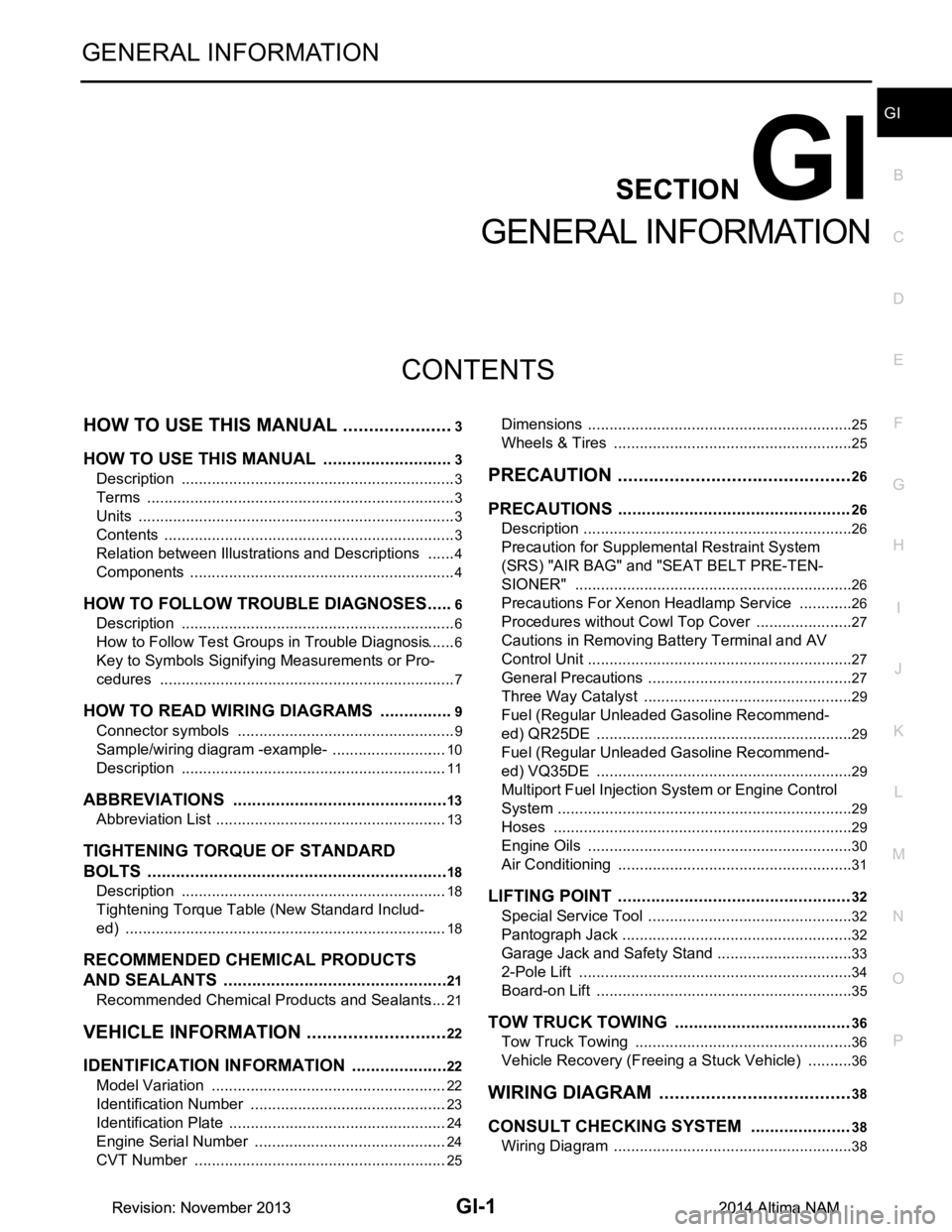
CONTENTS
GENERAL INFORMATION
HOW TO USE THIS MANU AL ......................3
HOW TO USE THIS MANUAL ....................... .....3
Description .......................................................... ......3
Terms ........................................................................3
Units ..........................................................................3
Contents ....................................................................3
Relation between Illustrations and Descriptions .......4
Components ..............................................................4
HOW TO FOLLOW TROUBLE DIAGNOSES .....6
Description ................................................................6
How to Follow Test Groups in Trouble Diagnosis ......6
Key to Symbols Signifying Measurements or Pro-
cedures ............................................................... ......
7
HOW TO READ WIRING DIAGRAMS ................9
Connector symbols ............................................. ......9
Sample/wiring diagram -example- ...........................10
Description ..............................................................11
ABBREVIATIONS .......................................... ....13
Abbreviation List .................................................. ....13
TIGHTENING TORQUE OF STANDARD
BOLTS ............................................................ ....
18
Description .......................................................... ....18
Tightening Torque Table (New Standard Includ-
ed) ....................................................................... ....
18
RECOMMENDED CHEMICAL PRODUCTS
AND SEALANTS ............................................ ....
21
Recommended Chemical Products and Sealants ....21
VEHICLE INFORMATION ............................22
IDENTIFICATION INFORMATION ................. ....22
Model Variation ................................................... ....22
Identification Number ..............................................23
Identification Plate ...................................................24
Engine Serial Number .............................................24
CVT Number ...........................................................25
Dimensions .......................................................... ....25
Wheels & Tires ........................................................25
PRECAUTION ..............................................26
PRECAUTIONS .................................................26
Description ........................................................... ....26
Precaution for Supplemental Restraint System
(SRS) "AIR BAG" and "SEAT BELT PRE-TEN-
SIONER" ............................................................. ....
26
Precautions For Xenon Headlamp Service .............26
Procedures without Cowl Top Cover .......................27
Cautions in Removing Battery Terminal and AV
Control Unit .......................................................... ....
27
General Precautions ................................................27
Three Way Catalyst .................................................29
Fuel (Regular Unleaded Gasoline Recommend-
ed) QR25DE ........................................................ ....
29
Fuel (Regular Unleaded Gasoline Recommend-
ed) VQ35DE ........................................................ ....
29
Multiport Fuel Injection System or Engine Control
System ................................................................. ....
29
Hoses ......................................................................29
Engine Oils ..............................................................30
Air Conditioning .......................................................31
LIFTING POINT .................................................32
Special Service Tool ................................................32
Pantograph Jack ......................................................32
Garage Jack and Safety Stand ................................33
2-Pole Lift ................................................................34
Board-on Lift ............................................................35
TOW TRUCK TOWING .....................................36
Tow Truck Towing ...................................................36
Vehicle Recovery (Freeing a Stuck Vehicle) ...........36
WIRING DIAGRAM ......................................38
CONSULT CHECKING SYSTEM .....................38
Wiring Diagram .................................................... ....38
Revision: November 20132014 Altima NAMRevision: November 20132014 Altima NAM
Page 2553 of 4801

IDENTIFICATION INFORMATIONGI-25
< VEHICLE INFORMATION >
C
D E
F
G H
I
J
K L
M B
GI
N
O P
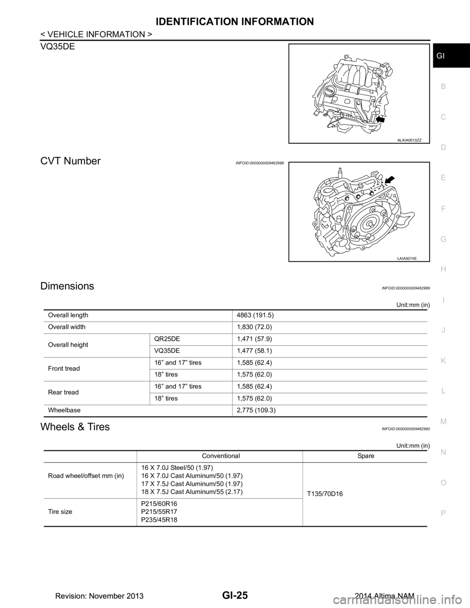
VQ35DE
CVT NumberINFOID:0000000009462988
DimensionsINFOID:0000000009462989
Unit:mm (in)
Wheels & TiresINFOID:0000000009462990
Unit:mm (in)
ALAIA0013ZZ
LAIA0074E
Overall length 4863 (191.5)
Overall width 1,830 (72.0)
Overall height QR25DE 1,471 (57.9)
VQ35DE 1,477 (58.1)
Front tread 16” and 17” tires 1,585 (62.4)
18” tires 1,575 (62.0)
Rear tread 16” and 17” tires 1,585 (62.4)
18” tires 1,575 (62.0)
Wheelbase 2,775 (109.3)
Conventional Spare
Road wheel/offset mm (in) 16 X 7.0J Steel/50 (1.97)
16 X 7.0J Cast Aluminum/50 (1.97)
17 X 7.5J Cast Aluminum/50 (1.97)
18 X 7.5J Cast Aluminum/55 (2.17) T135/70D16
Tire size P215/60R16
P215/55R17
P235/45R18
Revision: November 20132014 Altima NAMRevision: November 20132014 Altima NAM